
 ?Mathematical formulae have been encoded as MathML and are displayed in this HTML version using MathJax in order to improve their display. Uncheck the box to turn MathJax off. This feature requires Javascript. Click on a formula to zoom.
Abstract
This study investigates the load-bearing behavior of timber members subjected to combined compression and bending based on the guidelines of the standard Eurocode 5. In this context, two design approaches are stated to account for flexural buckling: the effective length method and the second-order analysis. Although Eurocode 5 states that second-order analysis can be carried out to check the stability of beam-columns, it does not mention how to formulate this analysis. This study investigates this case in order to develop alternative interaction formulae to check the stability of timber members subjected to simultaneously acting axial compression and bending moments with risk of buckling failure. The second-order analysis advanced in this article can be an alternative tool to be used by the structural engineer to assess the stability of axially loaded members subjected to the risk of flexural buckling failure.
1. Introduction
In modern timber frame structures, instability of beam-columns is one of the most important problems facing designers. Eurocode 5 (EN 1995 Eurocode 5 Citation2003) proposes interaction formulae in order to account for both buckling and lateral torsional buckling. This formulation considers the interaction of combined bending moment and compression. For the ultimate limit state analysis, Eurocode 5 (EN 1995 Eurocode 5 Citation2003) recommends using a linear interaction model for combined axial compression and bending for members with buckling failure. In this interaction model, the buckling factor, kc is employed to reduce the compressive strength parallel to the grain of the timber member in order to account for buckling. For stocky, non-slender members, without risk of buckling failure, a significant non-linear plastic deformation of the compression zone of the cross-section can occur before failure, and nonlinear interaction behavior can thus be guaranteed by setting the compression part of the equation to the power of 2.
In this context, Eurocode 5 states two design approaches:
Effective length method. The calculation of interaction formula is based on simple first-order analysis for the internal forces (compression and bending loads). This method is adopted by Eurocode 5 and described in detail.
Second-order analysis. In this method, the internal forces are calculated by second-order analysis, to take into account the non‐linear deformation caused by the increasing eccentricity of the external load. There is, however, no mention in Eurocode 5 of how to formulate the interaction formulae based on second-order analysis. The feasibility of this method is studied by several authors (Buchanan Citation1984; Steiger and Fontana Citation2005; Theiller and Frangi Citation2012).
For the second-order structural analysis, the impact of moisture content and the duration of loading, the two properties that affect the plastic or creep deformation of the material, are not explicitly considered. Consequently, the stiffness of the structural member is reduced by adjusting the design value of the modulus of elasticity (MOE) or by using a buckling modulus (Theiler Citation2014). Steiger and Fontana (Citation2005) maintain that the two approaches are not fully consistent, especially for columns with high slenderness ratios.
In the effective length method, the non-linear effects of combined axial and bending loads (P-delta effect) are taken implicitly into account through a buckling factor, kc. The buckling factor is used here to reduce the compression strength of the timber column-beam.
It worth noting that in the current version of Eurocode for the design of steel structures (EN 1993 Eurocode 3 Citation2010), the second-order analysis is taken into account. Of course, in steel structures the problem is rather complicated due to the plastic behavior of cross-section classes, but noting that for steel sections with class 3, which is designed using only elastic theory, similar to the case of timber structures, the second-order analysis is still considered. Further, a modification on the MOE in order to improve the results of second-order analysis is suggested (Steiger and Fontana Citation2005; Theiller and Frangi Citation2012). However, it can be shown that this approach cannot solve the problem of the difference in results between the Eurocode approach (effective length method) and the second-order analysis.
Kollar (Citation2008) suggested an approximate solution to take into account the second-order effects on structural frames. Expressions are presented for the calculation of the buckling load of building structures. This study can suitable for concrete structures in which the effect of the stiffnesses of the frames and/or the shear walls and the deformability of the foundations play an important role in the global analysis of the whole building structure. Fenollosa, Alonso Dura, and Llopis-Pulido (Citation2016) investigated the second-order effects in steel-concrete composite columns of the unbraced frames. Iu et al. (Citation2008) performed a direct second-order elastic analysis for steel frame design. The authors adopted a system analysis for a whole structure instead of taking the second-order effects indirectly by virtue of design specifications for every member. It is noteworthy to indicate here that for steel structures and steel-concrete composite structures, the second-order analysis for the structural stability should include the plastic effects. However, this case is not suitable for timber structures, which are structurally controlled by its elastic behavior. At any rate, the concept of global analysis of the whole structure can still be considered of interest to investigate further. Galishnikova et al. (Citation2018) investigated the instability of single columns without large deflections by means of the second-order structural theory including the influence of imperfections on the behavior of such structural elements. However, the study does not discuss how these effects can be included the interaction formulae for flexural buckling. Furthermore, a comparison study with the formulations in building codes has not been performed. Kim and Choi (Citation2011) analyzed the inelastic static and dynamic stability of a column subjected to a nonconservative force using the finite element method. The study can be suitable if the timber structures are analyzed in view of nonconservative systems, which is rarely used for typical timber structures in practice. Bedon et al. (Citation2015) discussed theoretically and experimentally the assessment of the typical buckling behavior and resistance of in-plane compressed timber log-walls. In such walls, the plate buckling, and boundary conditions are two important aspects to be considered when predicting the structural stability and capacity of the building system. However, since the boundary conditions are complex to predict, a generalized buckling design method has not been advanced. In the same context, Bedon and Fragiacomo (Citation2017) analyzed the buckling design using a FE modeling for in-plane compressed timber log-walls in accordance with the Eurocode 5. Non-dimensional buckling curves are proposed for timber log-walls under in-plane compression. Technically, the last two studies are specifically related to a special building system (Blockhaus structural systems), which can be constructed by assembling multiple timber logs. These timber logs can interact with each other by means of simple contact mechanisms (e.g. tongues and grooves). Schnabl, Turk, and Planinc (Citation2011) proposed an alternative semi-analytical model for structural behavior of timber columns exposed to fire. The results showed that the proposed method is conservative compared to the two simplified calculation methods offered by Eurocode 5 if the transfer of water is neglected, while, on the other hand, the results agree well for a water content of 12%. Further literature studies on the stability problem of timber structures can also be found in Steiger and Fontana (Citation2005) and Theiler (Citation2014).
Although Eurocode 5 states that second-order analysis can be carried out to check the stability of beam-columns, it does not mention how to formulate this analysis. This study investigates this case in order to develop alternative interaction formulae to check the stability of timber members subjected to simultaneously acting axial compression and bending moments with risk of buckling failure.
In this article, a fairly new approach is advanced based on the second-order analysis. In this context, two methods are developed to derive the interaction formulae for the flexural buckling. The first method does not consider the initial out-of-straightness of beam-column, while the second method does. Further, the article discusses other aspects such as the case of no risk for bucking failure and the modification of the elasticity modulus. It is thought that the structural engineer will have an alternative way to check the stability problem of timber members due to flexural buckling. In this respect, an example application of a timber beam is presented, in order to compare both methods and to demonstrate the feasibility of the derived interaction formulae. Two cases are analyzed: a statically indeterminate continuous beam and a statically determinate beam, because these two types of beams are common in framed timber structures but also because this case has not been fully investigated in the literature reviewed previously. The discussion is limited to the case of timber elements subjected to combined compression (parallel to the grain) and bending, which exhibits buckling failure according to the Eurocode 5 building standards. Furthermore, the article presents analytical calculations only.
2. Interaction formulae for flexural buckling to Eurocode 5
For members subjected to combined bending and axial compression parallel to the grain with risk for buckling, the following interaction formulae must be satisfied (EN 1995 Eurocode 5 Citation2003):
(1)
(1)
(2)
(2)
where
is the design compressive stress,
is the design compressive strength,
is = 0.7 for rectangular sections and =1.0 for circular sections,
and
are the design bending stresses about the principal y and z axes, respectively,
and
are the design strengths about the principal y and z axes, respectively,
and
where Wy and Wz is the section modulus about the y axis (strong axis) and z axis, respectively, where My,Ed is here the maximum initial moment according to first-order theory, which coincides with maximum deflection of the beam-column and
where NEd is the design normal force and A is the cross-sectional area of the structural member. EquationEquations (1)
(1)
(1) and Equation(2)
(2)
(2) are valid only in the case where there exists flexural buckling failure (i.e., λrel,y and/or λrel,z > 0.3), where
(3)
(3)
(4)
(4)
where
is the fifth percentile value of the MOE parallel to the grain, fc,0,k is the characteristic compression strength along the grains. The design compressive strength along the grains reads
(5)
(5)
and the design bending strength reads
(6)
(6)
where kmod is a modification factor taking into account the effect of the duration of loading and the moisture content and fm,k is the characteristic value of bending moment capacity, γM is the partial factor for a material property, kh is the factor to take into account the volume effect, which can be set equal to 1.0 for h > 600 mm for glulam timber and for h > 150 mm for solid timber, where h is the depth for bending members and λ is the slenderness ratio given by
(7a)
(7a)
(7b)
(7b)
where Lcr = βL is the effective buckling load, β is the factor for buckling depending on the support conditions and the load, L is the element length, and i is the radius of gyration. The buckling reduction factors
and
can be obtained as
(8)
(8)
(9)
(9)
in which
(10)
(10)
(11)
(11)
where βc = 0.2 for solid timber and = 0.1 for glue-laminated timber.
3. Second-order linear elastic analysis of single structural members
The following includes a presentation of the theoretical background of the problem, with the aim of deriving the formulas to check flexural buckling using second-order analysis.
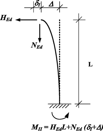
If a beam-column is loaded with compression force and bending moment, the initial bending deflection together with the axial load will lead to an initial bending moment MI (first-order moment). If the axial load is high enough to increase the column deflection, it would be necessary to consider this effect on the total deflection of the structural member. This phenomenon is known as the P-δ effect, which eventually causes a second-order moment, MII. shows a cantilever column subjected to axial compression force, NEd and transversal force, HEd, where Δ is the additional deflection of the column due to loading actions.
Figure 1. A column subjected to axial force, NEd and transversal force HEd.
The relation between the two moments can be obtained as (Bazant and Cedolin Citation1991)
(12)
(12)
where Ncr is the Euler buckling load. EquationEquation (12)
(12)
(12) may be simplified by assuming sinusoidal bending moment as
(13)
(13)
Although this is an approximate solution, it is accurate to within 2% for values of NEd/Ncr less than 0.6, which is applicable for most cases in practice. The second-order deflection in this case may be written as
(14)
(14)
where δI and δII are the first- and second-order deflections, respectively. EquationEquation (13)
(13)
(13) neglects the deformation effect due to initial out-of-straightness. If this effect is to be considered, then the relation between second- and first-order moments may be written as (Al-Emrani et al. Citation2008)
(15)
(15)
where e0 is the initial out-of-straightness (=L/500) for glued laminated (glulam) timber sections and (=L/300) for solid timber sections. Consequently, the second-order deflection can be obtained as
(16)
(16)
For members subjected to flexural buckling (combined biaxial moments about y-y and z-z bending and axial compression) with buckling failure, the previous analysis can now be applied to formulate the interaction relationships between moments and compressional forces using Navier’s formula (Gere and Timoshenko Citation1997). If the second-order moment obeys EquationEq. (13)(13)
(13) , then in this case the stresses should satisfy the following general expressions:
(17)
(17)
(18)
(18)
where
(19a)
(19a)
(19b)
(19b)
The buckling load around y-y and z-z may be expressed as
(20a)
(20a)
(20b)
(20b)
where E is the MOE; Lcr = βL is the effective buckling load where β is the factor for buckling depending on the support conditions and the load and L is the element length; and I is the second moment of inertia, depending on the loading axis.
According to Eurocode 5 (EN 1995 Eurocode 5 Citation2003), the design value of MOE for the second-order analysis is
(21)
(21)
E0, mean is the mean value of MOE, parallel to the grains, which is applicable to second-order linear elastic analysis of single structural members.
As with EquationEqs. (1)(1)
(1) and Equation(2)
(2)
(2) , the factor, km, in EquationEqs. (17)
(17)
(17) and Equation(18)
(18)
(18) is used here takes into consideration the stress redistribution for beams loaded in flexure about both major axes, when the buckling plane does not move in the same direction as the bending plane. Subsequently, EquationEq. (17)
(17)
(17) is the alternative form for EquationEq. (1)
(1)
(1) , which is used to evaluate the buckling about y-y. In the same context, EquationEq. (18)
(18)
(18) is the alternative form for EquationEq. (2)
(2)
(2) which is used to evaluate the buckling about z-z.
If, on the other hand, the second-order moment obeys EquationEq. (15)(15)
(15) , then in this case the stresses should satisfy the following general expressions:
(22)
(22)
(23)
(23)
where
and
in which MII,y and MII,z are the second-order bending moments around y-y and z-z, respectively, in accordance with EquationEq. (15)
(15)
(15) .
4. Example application
The beam in the following two cases is made of glued laminated timber of class GL32c and shows the material properties. The design value of the effects of actions is qEd = 10 kN/m and the normal compressive force, NEd = 300 kN. Two cases are now investigated as follows.
Table 1. Material properties of glulam timber with strength class GL32c.
4.1. Statically indeterminate beam
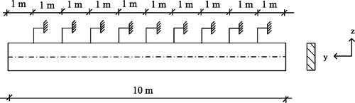
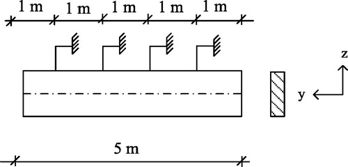
The beam in is a continuous beam on three supports, which is subjected to axial and flexural loading. The design section for the interaction formulae is taken at x = 5 m, so the design forces can be calculated as NEd = 300 kN and MEd,y = qEd L2/8 = 31.25 kNm, where My,Ed is here the maximum initial moment at support B according to first-order theory. The assumed buckling curve of the beam is shown in . The buckling length of the beam may be roughly compared with a beam that is fixed at one end and simply supported at the other end. In this case, β ≈ 0.85 (EN 1995 Eurocode 5 Citation2003). Discrete wood restraints (or lateral supports) are placed at the compressed edge, at 1.0 m c/c as shown in . Such a bracing system is typical in practice, mainly to prevent the lateral torsion but also to minimize the flexural buckling of the beam around the z-z axis, . In this case, Lcr,y =βL ≈ 4.25 m and Lcr,z ≈ 1.0 m. The first-order deflection of the beam obeys: The initial out-of-straightness reads in this case: e0 = L/500 = 10/500.
Figure 2. A continuous beam on three supports. The dashed line is the assumed buckling curve of the beam.
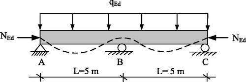
Figure 3. Discrete bracing of the beam () at the upper level of the beam (compressive edge) with lateral supports.
4.2. Statically determinate beam
The beam shown in is a simply supported beam subjected to the same axial and flexural loading as before. The design section for the interaction formulae is taken at x = 2.5 m, so the design forces can be calculated as NEd = 300 kN and MEd,y = qEd L2/8 = 31.25 kNm, where My,Ed is here the maximum initial moment according to first-order theory. The buckling length of the beam may be taken typically as β = 1.0 (EN 1995 Eurocode 5 Citation2003). Discrete wood restrains are placed on at the compressed edge, at 1.0 m c/c as shown in . In this case, Lcr,y =βL= 5 m and Lcr,z ≈ 1.0 m. The first-order deflection of the beam obeys: The initial out of straightness is: e0 = L/500 = 5/500.
Figure 4. A simply supported beam. The dashed line is the assumed buckling curve of the beam.
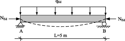
Figure 5. Discrete bracing of the beam () at the upper level of the beam (compressive edge) with lateral supports.
4.3. Method
For both cases, the flexural buckling may now be evaluated in accordance with the derived interaction formulae, EquationEqs. (17)(17)
(17) , Equation(18)
(18)
(18) , Equation(22)
(22)
(22) , and Equation(23)
(23)
(23) together EquationEqs. (1)
(1)
(1) and Equation(2)
(2)
(2) . In this context, a parametric study is carried out with different standard cross-sections. The dimensions are selected so that buckling failure should exist in the beam, i.e., λrel > 0.3.
5. Discussion
The results are shown in and . As can be seen, both calculation methods (the effective length method as adopted by Eurocode 5 and the second-order analysis) agree well. However, it is apparent that the interaction formulae (EquationEqs. (22)(22)
(22) and Equation(23)
(23)
(23) ), which contain the term: initial out-of-straightness (e0d) in EquationEq. (15)
(15)
(15) yield relatively higher results in most cases. This effect is evident when the beam length is increased and accordingly the value of e0d. Further, one can see that as ratio h/b > 3, the two methods, EquationEqs. (1)
(1)
(1) , Equation(2)
(2)
(2) , Equation(17)
(17)
(17) , and Equation(18)
(18)
(18) will yield almost identical results. Additionally, the results of and indicate that the second-order analysis yields slightly higher values for some cross-sections (about 10%) than EquationEqs. (1)
(1)
(1) and Equation(2)
(2)
(2) , possibly due to the effect of second-order moment, which is not fully considered by the effective length method. This conclusion is valid for both investigated cases, i.e., when the beam is statically indeterminate or determinate.
Table 2. The effect of beam dimensions on the beam stability, , with different interaction formulae.
Table 3. The effect of beam dimensions on the beam stability, , with different interaction formulae.
The flexural buckling values around the weak axis (z-z) calculated using the Eurocode method EquationEqs. (1)(1)
(1) and Equation(2)
(2)
(2) and the first method EquationEqs. (17)
(17)
(17) and Equation(18)
(18)
(18) for both cases ( and ) are here the same, because the applied loading conditions and buckling lengths are the same. Only the flexural buckling around y-y is affected due to the buckling length, which is longer in the case of the statically determinate beam than in the case of the statically indeterminate beam. Subsequently, higher value of flexural buckling is obtained for the case of statically determinate beam. However, if the term e0d is considered, as formulated in the second method EquationEqs. (22)
(22)
(22) and Equation(23)
(23)
(23) , then the results will be different for both cases due to the difference in beam lengths, as indicated previously.
Note that in Steiger and Fontana (Citation2005) and Theiller and Frangi (Citation2012) it is concluded, based on experimental results, that the design value of MOE can instead be calculated on the 5th percentile E = E0.05 or tangent MOE (T ≈ 0.8Emean). In Theiler (Citation2014) other formulae are suggested, in order to have good agreement with numerical simulations. It can be shown, however, that these suggestions will have little impact on the present results.
6. Concluding remarks
In this article, two methods are presented to derive the interaction formulae for the flexural buckling based on the second-order analysis. The first method does not consider the initial out-of-straightness of beam-column, while the second method does. Due to this effect, relatively higher values of the interaction formula were obtained as compared with the Eurocode formulation and the first method. In this context, an improved safety marginal for longer beam-columns can, thus, be obtained as compared with the Eurocode formulation of the problem. However, further experimental investigations may be needed to confirm this conclusion. Technically, in the Eurocode formulation, there is a factor, which evaluates straightness, βc, EquationEq. (10)(10)
(10) . This coefficient evaluates the initial out-of-straightness limits (L/500 for glulam and L/300 for solid timber). However, the coefficient is set equal to a representative constant value that is not specifically a function of the length, L.
From an instructive point of view, the first method as formulated by EquationEqs. (17)(17)
(17) and Equation(18)
(18)
(18) does not consider the initial out-of-straightness of beam-column since it can be considered relatively small for typical beam-columns length (<3%). The flexural buckling is initiated solely due to the effect of applied transversal loads and vertical loads. The second method as formulated by EquationEqs. (22)
(22)
(22) and Equation(23)
(23)
(23) will imply that the initial out-of-straightness of beam-column will result in a relatively small second-order moment even though there is no applied transversal loads on the beam-column, as inspected by EquationEq. (15)
(15)
(15) .
For stocky non-slender members (λrel,y and λrel,z ≤ 0.3), there will be no risk for buckling failure and the interaction relationships will be no longer elastic. Instead, the non-linear, plastic deformation of the compression part of the cross-section will govern the interaction between the bending moments and axial forces. When superposing compression and bending stresses, interaction behavior can thus be guaranteed by setting the compression part in EquationEqs. (1)(1)
(1) and Equation(2)
(2)
(2) to the power of 2 (EN 1995 Eurocode 5 Citation2003). It can be shown that in this case, the effect of second-order moment on the interaction results will be very small and can thus be neglected. Consequently, in many cases in practice, there will be no need to consider the second-order effects on the interaction formulae for non-slender members that exhibit no risk of flexural buckling.
The second-order analysis as advanced in this paper can be an additional and effective tool that structural engineers can safely use to assess the stability of axially loaded members subjected to the risk of flexural bucking failure.
From an engineering education perspective, the example discussed in this paper may be used as an innovation application brief or as suitable exercises for mechanical and civil engineering students. It is demonstrated how stability problem of timber elements, treated in Eurocode 5 standard, can be solved using an alternative approach without too much effort. For comparison, the Eurocode formulations may be utilized to confirm the results. As a last observation, the examined analytical models presented in this article can effectively be used in cold conditions only.
References
- Al-Emrani, M., B. Engström, M. Johansson, and P. Johansson. 2008. Bärande konstruktioner, del 1 (load-bearing structures, part 1). Göteborg: Institutionen för bygg och miljöteknik, Chalmers Technical University.
- Bazant, Z. P., and L. Cedolin. 1991. Stability of structures: Elastic, inelastic, fracture, and damage theories. New York: Oxford University Press.
- Bedon, C., and M. Fragiacomo. 2017. Derivation of buckling design curves via FE modelling for in-plane compressed timber log-walls in accordance with the Eurocode 5. European Journal of Wood and Wood Products 75 (3):449–465.
- Bedon, C., G. Rinaldin, M. Izzi, M. Fragiacomo, and C. Amadio. 2015. Assessment of the structural stability of Blockhaus timber log-walls under in-plane compression via full-scale buckling experiments. Construction and Building Materials 78 (1):474–490.
- Buchanan, A. H. 1984. Strength model and design methods for bending and axial load interaction in timber members. Dissertation, University of British Columbia.
- EN 1995 Eurocode 5 2003. Design of timber structures, part 1-1: General-Common rules and rules for buildings. CEN/TC 250, European Committee for Standardisation, Brussels.
- EN 1993 Eurocode 3 2010. Design of steel structures, part 1-1: General- Common rules and rules for buildings. CEN/TC 250, European Committee for Standardisation, Brussels.
- Fenollosa, E., A. Alonso Dura, and V. Llopis-Pulido. 2016. Second-order effects in steel-concrete composite columns of the unbraced frames. Journal of Civil Engineering and Construction 5 (1):42–55.
- Galishnikova, V. V., T. H. Gebre, S. A. M. Al-Sabri, and O. Saffia-Doe. 2018. Second order structural theory for the stability analysis of columns. Structural Mechanics of Engineering Constructions and Buildings 14 (3):192–197.
- Gere, J. M., and S. P. Timoshenko. 1997. Mechanics of materials. Boston: PWS Publishing Company.
- Iu, C. K., W. F. Chen, S. L. Chan, and T. W. Ma. 2008. Direct second-order elastic analysis for steel frame design. KSCE Journal of Civil Engineering 12 (6):379–389.
- Kim, N., and D. Choi. 2011. Inelastic static and dynamic stability analyses of a column subjected to a nonconservative force. Mechanics Based Design of Structures and Machines 39 (3):346–366.
- Kollar, L. 2008. Second order effects on building structures – an approximate evaluation, creating and renewing urban structures – tall buildings, bridges and infrastructure. 17th Congress Report of IABSE, Chicago.
- Schnabl, S., G. Turk, and I. Planinc. 2011. Buckling of timber columns exposed to fire. Fire Safety Journal 46 (7):431–439.
- Steiger, R., and M. Fontana. 2005. Bending moment and axial force interacting on solid timber beams. Materials and Structures 38 (279):507–513.
- Theiler, M. 2014. Stabilität von axial auf Druck beanspruchten Bauteilen aus Vollholz und Brettschichtholz (Stability of components subjected to axial stress on solid wood and glued laminated timber). Dissertation No. 22062. Zürich: ETH Zürich.
- Theiller, M., and A. Frangi. 2012. Design of timber columns based on 2nd order structural analysis. Working commission W18-timber structures, International council for research and innovation in building and construction, Växjö, Sweden.