
 ?Mathematical formulae have been encoded as MathML and are displayed in this HTML version using MathJax in order to improve their display. Uncheck the box to turn MathJax off. This feature requires Javascript. Click on a formula to zoom.
Abstract
A leaf spring is a simple form of spring commonly used for the suspension in wheeled vehicles. Due to their high strength to weight ratio, high stiffness, and high impact energy absorption, fiber-reinforced composite leaf springs gain considerable interest recently as a potential alternative to conventional leaf springs with relatively high weight. In the present study, a novel composite leaf spring consists of two composite face layers, and a soft and flexible viscoelastic core is proposed. Employing viscoelastic materials in structures reduces undesirable vibrations leading to fatigue and damage of structures. A numerical method is used to design and analyze composite leaf springs with a viscoelastic core using the Abaqus software package. Results are compared with those from well-known analytical methods, finite element methods, and experiments. Results show that the proposed novel composite leaf spring can withstand the stresses caused by static and impact forces, reduce post-impact vibrations, and prevent undesirable system vibrations. The viscoelastic layer increases the strain energy capacity of proposed composite leaf springs compared to conventional composite leaf springs and enhances the composite leaf spring performance against bump impact.
1. Introduction
The automobile industry has attempted to reduce the overall weight of automobiles continually. Composite components are a viable alternative to steel parts from a weight reduction point of view. Steel leaf spring is a potential item with relatively high weight which can be replaced by composite parts (Kumar and Vijayarangan Citation2007b; Rajesh et al. Citation2016) as steel leaf spring accounts for 10%–20% unsprung weight of the automobile. Because of the unique properties of fiber-reinforced polymer (FRP) leaf springs, such as high strength to weight ratio, excellent fatigue resistance, outstanding corrosion resistance, and high elastic strain energy ratio, they gained credibility in the industry (Rajendran and Vijayarangan Citation2001; Hou et al. Citation2007; Polach and Hajžman Citation2011).
In recent decades, design, test, and optimization of composite leaf springs have received a significant amount of interest (Rajendran and Vijayarangan Citation2001; Hou et al. Citation2007; Kumar and Vijayarangan Citation2007b; Rajesh et al. Citation2016; Yang et al. Citation2019). Sancaktar and Gratton (Citation1999) attempted to design and manufacture a composite leaf spring for a solar vehicle in which weight reduction is an essential factor. They employed unidirectional E-glass reinforced epoxy composites to create the front suspension leaf spring, which was acceptable as it satisfies the design demand. Rajendran and Vijayarangan (Citation2001) proposed an approach to design optimal composite leaf springs using genetic algorithms. Based on the proposed method, the mono leaf composite spring is developed in which the overall weight of the leaf spring is decreased by 75.6% compared to the seven-leaf steel under the same design parameters and load conditions. Experimental tests were conducted on the glass fiber/epoxy composite (GFRP) leaf springs in moderately heavy vehicles such as a “Jeep automobile” in the laboratory and road tests. The results showed that single composite leaf springs are useful, and have lower flexure stresses and higher nominal shear stresses (Al-Qureshi Citation2001).
As the main objective of using composite leaf springs is to decrease weight, Shokrieh and Rezaei (Citation2003) attempted to design shape optimization composite leaf springs to reach the minimum weight. They replaced the four-leaf steel spring used in the rear suspension of a typical vehicle with GFRP composites. The results indicated that the optimum spring has a width that is decreased hyperbolically and a thickness that is increased linearly from the spring eye to the axel seat, which results in a weight reduction of up to 80%. Besides, it was shown that the natural frequency of the composite leaf springs is relatively higher than the road frequency to avoid resonance.
The numerical method is a viable, time-saving, and cost-effective method to analyze the composite leaf springs. Several studies have employed numerical methods such as the Finite Element Method (FEM) to examine the mechanical performance of composite leaf springs. A lightweight single E-glass/epoxy leaf spring was designed for a three-wheeler vehicle by Gebremeskel (Citation2013). A static test was carried out, and the fatigue life of spring was predicted. Results showed that this particular composite leaf spring satisfies the maximum stress failure criterion. Besides, the composite leaf spring was modeled and analyzed using Abaqus, and the stresses, the strains, and the displacements were determined and compared with the experimental results. Oztoprak et al. (Citation2018) developed polymer mono-leaf springs with different materials to replace conventional metal leaf springs. The manufactured composite leaf springs were studied experimentally and numerically. First, the mechanical properties of three different composite materials were determined by the experimental test, then imported to the Abaqus software, a good agreement was observed. The results indicated that the maximum stress is below the yielding stress. Also, the carbon fiber/epoxy leaf spring was stiffer than glass/epoxy and hybrid/epoxy leaf springs.
Most previous studies have focused on weight optimization and strength of composite leaf springs, while the damping characteristics of these structures have received relatively little attention. A few researchers examined the damping properties of composite leaf springs. Cherruault et al. (Citation2011) conducted quasi-static and dynamic testing of glass fiber/epoxy leaf springs for rail freight vehicles. The results showed that these composite springs have specific properties such as viscous damping and low dynamic stiffness, which are different from traditional metal leaf springs. Shi et al. (Citation2017) investigated the damping properties of glass fiber/polyurethane composite leaf springs for different configurations, numerically and experimentally. The results indicated that the laying angel and longitudinal tensile modulus of materials are two main factors that determine the damping characteristic of composite leaf springs.
In the present study, a novel composite leaf spring design with a viscoelastic core is proposed. Sandwich structures embedding viscoelastic layers are commonly used in many structural systems for vibration and noise control (Valvano, Alaimo, and Orlando Citation2019; Valvano, Orlando, and Alaimo Citation2019; Valvano, Alaimo, and Orlando Citation2020). Viscoelastic layer are added to structures to control vibration as it transforms vibrational energy into thermal energy (Song et al. Citation2009; Filippi, Carrera, and Valvano Citation2018; Alaimo, Orlando, and Valvano Citation2019; Alavi and Eipakchi Citation2019; Praharaj and Datta Citation2020). The proposed novel composite leaf spring is designed and analyzed to investigate the effect of the viscoelastic core on the damping characteristics of the composite leaf spring. A numerical method is employed to analyze the static and dynamic behavior of these composite leaf springs. The results show that adding the viscoelastic layer increases the strain energy capacity of composite leaf springs, which is a vital feature in leaf springs to absorb impact loads due to road irregularities.
2. Problem statement
In this research, the static and dynamic behaviors of composite leaf springs are investigated. First, a composite leaf spring with and without viscoelastic core under static loading is designed by considering the design criteria. In this regard, the appropriate viscoelastic model is employed to model the viscoelastic layer. Then, the effects of both static and impact loadings on the performance of the designed composite leaf spring are analyzed. In order to verify the numerical model, the composite leaf springs with viscoelastic core are modeled using a composite sandwich beam with a viscoelastic core. The dynamic analysis results are compared with those reported in the literature. Finally, the performance of the composite leaf spring with and without viscoelastic core is investigated to examine the effect of incorporation of viscoelastic layers in the design of such structures.
3. Geometry and materials
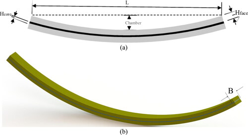
Composite leaf spring with the viscoelastic core, as shown in , is considered. shows the perspective view of the composite leaf spring. The dimensions of the composite leaf spring are identified. The chamber is 135 mm, and the distance between the eye spring (L) is 1300 mm. The viscoelastic thickness (Hcore), the composite thickness (Hface), and composite leaf spring width (B) is defined in .
Figure 1. The schematic of the composite leaf spring with viscoelastic core, (a) Front view of composite leaf spring (b) Perspective view of the composite leaf spring.
In the design of composite leaf springs, there are several design parameters and criteria (Rajendran and Vijayarangan Citation2001; Shokrieh and Rezaei Citation2003; Oztoprak et al. Citation2018) that must be satisfied, are listed below:
One-eighth of the vehicle weight is applied to each end of the composite leaf spring.
Half of the leaf spring is simulated due to the symmetry of geometry, loads, and boundary conditions, and hence it is modeled as a cantilever beam.
The maximum static deflection of the leaf spring is assumed to be 130 mm.
The reliability factor for static load ranges from 1.5 to 2, depending on the leaf spring application. Moreover, the dynamic load is higher than the static load, depending on the boundary conditions.
The natural frequency of the composite leaf spring must be higher than the natural frequency of the road, which is 12 Hz.
In the present study, carbon fiber/epoxy and E-glass/epoxy are selected as composite leaf spring; since these materials are the most common composite materials which are used to fabricate the leaf springs. The material properties (Pederson Citation2008; Al-Qrimli, Mahdi, and Ismail Citation2015; Oztoprak et al. Citation2018; Yousefi, Mosavi Mashhadi, and Safarabadi Citation2020) of these materials are reported in .where in , ρ is the material density, and E1 is the longitudinal modulus, E2, and E3 are the transitive modulus. ν12 and ν23 are the in-plane and out-of-plane Poisson’s ratios, respectively. G12 and G23 are the in-plane and out-of-plane shear modulus, respectively. Moreover, Xit and Xic, are the ultimate tensile stress and the ultimate compressive stress, respectively, in the i direction.
Table 1. Mechanical properties of E-glass/epoxy and carbon fiber composites (Pederson Citation2008, Al-Qrimli, Mahdi, and Ismail Citation2015, Oztoprak et al. Citation2018, Yousefi, Mosavi Mashhadi, and Safarabadi Citation2020).
The viscoelastic layer is assumed to be made of 3MISD112. It is noted that the viscoelastic properties of the 3MISD112 are determined by fitting the Prony series on the experimental stress-time curve.
4. Numerical modeling
4.1. Static modeling
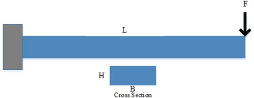
In the present study, to determine the equivalent stiffness, the composite leaf springs are subjected to static loads, as shown in . It is worth mentioning that the applied load is divided into ten-point loads to model the static loading condition because of the Abaqus limitation to apply force on edges. The static load of 420 N is applied on each point, and the maximum static deflection at each point is assumed to be 130 mm. To determine the width (B) and the thickness (H) of the cross-section, the composite leaf spring is assumed to be a cantilever beam, as illustrated in .
Figure 2. The leaf springs under the static load.
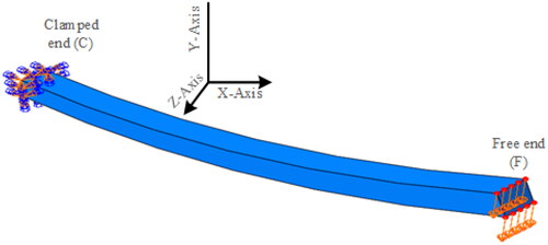
Figure 3. The composite leaf spring, modeled as a cantilever beam.
In order to determine the width and thickness of the composite leaf spring, the following equations are employed (Gebremeskel Citation2013):
(1)
(1)
(2)
(2)
where, L is the length of spring, E1 is elastic modulus in the direction of fibers, δmax is the maximum deflection, F is the static load, and σmax is the maximum stress in the direction of fibers. The optimum values of width and thickness of composite leaf springs are identified after determining the initial value of width and thickness of leaf spring by calculating the stress and deflection, employing Abaqus software. Results are verified with the Gebremeskel study (Gebremeskel Citation2013).
In the next step, to determine the optimum dimensions of composite leaf springs with the viscoelastic core, the thickness identified in the previous step for composite leaf springs without viscoelastic core is considered. Afterward, this leaf spring is subjected to the static load to perceive if this structure satisfies the design conditions. A trial and error method is employed to design the composite leaf spring with a viscoelastic core, which satisfies the design parameters. For a sufficiently precise amount of stiffness of composite leaf spring with viscoelastic core, for each viscoelastic core thickness, the thickness of the composite layer is determined by increasing the thickness of the composite layer until the desired amount is obtained. It is noted that in the present study, three types of composite leaf springs with different viscoelastic core thicknesses (2, 4, and 6 mm) are considered.
4.2. Dynamic modeling
After designing the composite leaf springs with and without the viscoelastic core, both models are subjected to impact loads to take into account the effect of bump and road irregularities. By increasing the energy storage capability feature of composite leaf springs, the leaf springs absorb wider ranges of vertical vibrations and impacts, protecting the passenger leading to a comfortable ride (Kumar and Vijayarangan Citation2007a). Therefore, in the present study, the aim is to expand this distinguishing feature (energy storage capability) by adding a viscoelastic layer in the typical composite leaf spring.
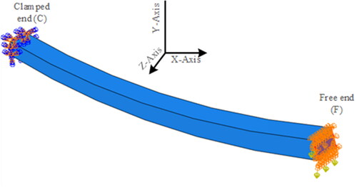
In the dynamic loading analysis, the boundary conditions () are similar to the road test conditions. The leaf spring is assumed to be a cantilever beam with a clamped end, and the free end deflects only in the vertical direction. In these circumstances, the deflection and stress applied to the leaf spring are less than the static load condition, which satisfies the design criteria.
Figure 4. Dynamic boundary conditions.
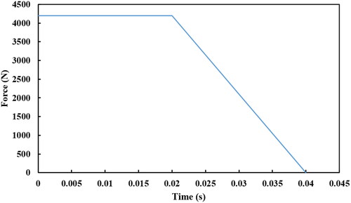
The load conditions and amplitude are shown in . It should be noted that the overall load includes two main parts: the static weight load of the structure and the impact load.
Figure 5. Impact load profile.
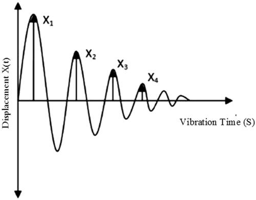
In order to compare the level of damping in both the composite leaf springs with the viscoelastic layer and without the viscoelastic layer, the damping ratio (ξ) is determined. The damping ratio is defined as (Thomson Citation2018):
(3)
(3)
where δ is logarithmic decrement defined as:
(4)
(4)
In EquationEq. (4)(4)
(4) , X1 and X2 are vibration amplitudes of two successive vibration peaks which are shown in .
Figure 6. Vibration displacement versus time.
4.3. Viscoelastic core modeling
Manufacturers present the experimental data of viscoelastic materials in the frequency domain, so to use these data in the form of a time-domain, the presented data should be reformed (Slanik et al. Citation2000). The shear modulus for linear viscoelastic materials in the frequency domain form is defined as:
(5)
(5)
where
is the loss factor for viscoelastic materials.
and
are the storage and the loss moduli for shear in viscoelastic materials, respectively.
Viscoelastic materials can be presented as combinations of viscus and elastic elements such as springs and dashpots. Researchers have proposed several models based on the basic models proposed by Maxwell and Voigt-Kelvin models. Tschoegl proposed a model in which the complex shear modulus can be defined for N terms in the frequency domain as:
(6)
(6)
In EquationEq. (6)(6)
(6)
and ω is the frequency. The series in EquationEq. (6)
(6)
(6) is known as the Nth term of the Prony series in the frequency domain.
and
are material parameters, and G0 is the instantaneous shear modulus.
Next, the complex shear modulus presented in EquationEq. (6)(6)
(6) is converted to the time-domain form of relaxation modulus. To this aim, the inverse Laplace transform is taken to acquire the relaxation modulus in time:
(7)
(7)
Also, the Prony series of relaxation shear modulus could be defined as:
(8)
(8)
EquationEquation (8)(8)
(8) can be presented as:
(9)
(9)
Material parameters Ge, Gn, and τn can be determined using Rogers’s algorithm by fitting polynomials curve in the frequency domain to the complex modulus. It is noted that the mechanical properties of 3MISD112 are imported to Abaqus as Prony series expressions. The material parameters (Slanik et al. Citation2000) of 3MISD112 required for Prony series expressions for N = 8 are listed in .
Table 2. Prony series expressions (Slanik et al. Citation2000).
4.4. Mesh
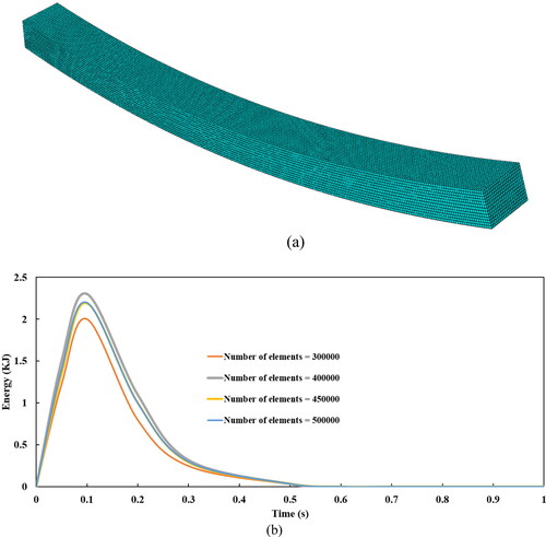
In the present study, as shown in , the general-purpose linear three-dimensional 8-node linear hexahedral elements, C3D8R, are used to mesh the whole structure. For a sufficiently accurate size of element for each leaf spring, the number of elements is increased until the value of the Kinetic energy-time curve converges to the same amount despite changing the mesh size. In the present study, to converge the value of the Kinetic energy-time curve to the same amount. As indicated in , by increasing the number of elements (reduce mesh size), the Kinetic energy curve converges when the number of elements is more than 500,000. Therefore, in the present study, the number of elements is chosen at least 500,000.
Figure 7. Meshing technique (a) A typical Meshed composite leaf spring (b) Effect of number of elements on the Kinetic energy curve.
4.5. Verification
To verify the proposed model, the natural frequencies of composite leaf springs with viscoelastic core are compared with composite sandwich beams with the viscoelastic core. The material and geometrical properties of the sandwich beam are reported in . The results are compared with those reported in the literature (Mead and Markus Citation1969; Johnson and Kienholz Citation1982; Mace Citation1994; Fasana and Marchesiello Citation2001; Arikoglu and Ozkol Citation2010) and presented in .where in , the loss factor is a damping property of the viscoelastic core (Shi, Sol, and Hua Citation2006).
Table 3. Materials and configuration of benchmark sandwich beam to verify the proposed model.
Table 4. Natural frequency of the composite sandwich beam.
Furthermore, FEM results (in the present study) of the composite leaf spring are compared with another experiment data (Felippe Filho et al. Citation2017) for a beam with two elastic layers (base beam and restraining layer, both fixed) and a viscoelastic layer to verify the accuracy of the obtained dynamic results ().
Table 5. Comparing the natural frequency and damping ratio of the composite sandwich beam.
According to and , results from the proposed model in the present study are in good agreement with those reported in previous researches.
5. Results and discussion
5.1. Design and analysis of composite leaf spring
5.1.1. The E-glass/epoxy composite leaf spring
In this section, first, the composite leaf spring without a viscoelastic core is analyzed. In this regard, the E-glass/epoxy composite leaf spring is examined under static and impact loading, respectively. Then, it is compared with E-glass/epoxy composite leaf spring with the viscoelastic core.
The initial thickness and width of the composite leaf spring as a cantilever beam considering the reliability factor of 2 is determined as:
The thickness and width, according to EquationEqs. (1)(1)
(1) and Equation(2)
(2)
(2) , are 28 and 40 mm, respectively. After identifying the initial value of the cantilever beam dimension, the composite leaf spring in which the length and chamber are 1300 and135 mm is designed. Since dimensions are specified for a cantilever beam, these values must be modified for the composite leaf spring. Therefore, as explained in section (4.1), the width is increased until the specified values satisfy the design criteria. The results are listed in .
Table 6. Designed E-glass/epoxy composite leaf spring.
After determining the E-glass/epoxy composite leaf spring without viscoelastic core, the E-glass/epoxy composite leaf spring with the viscoelastic core is designed and analyzed. The design process is the same as composite leaf spring without viscoelastic core, although to satisfy the design criteria, the thickness and width of composite must be increased. Stress distribution in the E-glass/epoxy composite leaf spring subjected to static loads is presented in . In , the stress distribution along fibers is demonstrated for composite leaf spring without the viscoelastic core. Results illustrate that the maximum stress along fibers (S11) is 500 MPa. Since the amount of ultimate tensile stress is 1035 MPa, the maximum stress criteria across fibers are satisfied. shows the stress distribution along fibers for composite leaf spring with a viscoelastic thickness of 2 mm. The maximum stress is 408.2 MPa, which is less than the maximum stress along fibers (S11) is 500 MPa. By comparing , it is acquired that by adding the viscoelastic core, the amount of maximum stress is reduced.
Figure 8. Static results of E-glass/epoxy composite leaf spring without viscoelastic core and with a viscoelastic core thickness of 2 mm.
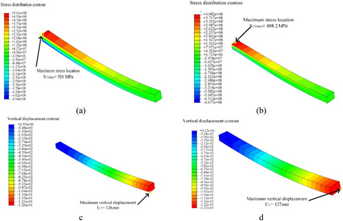
show the vertical deflection (U2) of E-glass/epoxy composite leaf spring without viscoelastic core and with a viscoelastic core thickness of 2 mm, respectively under static load. It is shown that the maximum deflection is 127 mm. According to Hook’s low, the spring’s stiffness for E-glass/epoxy composite leaf spring without viscoelastic core and with a viscoelastic core thickness of 2 mm is 33.33 and 33.07 kN/m.
In the next step, the E-glass/epoxy composite leaf spring is analyzed dynamically by employing Abaqus. The impact load of 4200 N () is applied to the leaf spring designed under static load. shows the dynamic response of composite leaf springs without the viscoelastic core.
Figure 9. Dynamic response of E-glass/epoxy composite leaf spring without viscoelastic core.
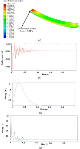
Results show () that the stress in the direction of fibers (S11) is 84 MPa, which is less than the static condition because of changing boundary conditions in the dynamic analysis. In the dynamic condition, the reliability factor is 4.5 based on maximum stress criteria.
Impact response is another crucial feature of composite leaf springs, which is considered in the present study. elucidate the deflection-time, kinetic energy, and strain energy curve, respectively, for the free end of leaf spring.
shows the deflection-time curve in the vertical direction. This graph shows that after impact loading, the maximum deflection amplitude is 13.89 mm, then the deflection converges into 4 mm. The damping ratio is determined, according to EquationEqs. (3)(3)
(3) and Equation(4)
(4)
(4) as:
In this system, the ξ < 1, so the system is underdamped. The system vibrates with a gradual decrement and eventually stop vibration. represents how kinetic energy has changed over time. The vertical axis shows the maximum kinetic energy is 2100 J approximately, and the horizontal axis represents that it takes 0.7 s to leaf spring stabilization. shows the strain energy fluctuation over time. The maximum strain energy is 100 J approximately.
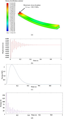
shows the dynamic response of E-glass/epoxy composite leaf spring with a viscoelastic core thickness of 2 mm. shows the stress contour across fiber (S11), displacement-time of the free edge, kinetic energy, and strain energy of E-glass/epoxy composite leaf spring with a viscoelastic core thickness of 2 mm.
Figure 10. Dynamic response of E-glass/epoxy composite leaf spring with a viscoelastic core thickness of 2 mm.
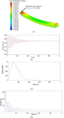
shows that the maximum stress in fibers’ direction is 121.3 MPa, which is higher than the composite leaf spring without viscoelastic core under the impact loading, although in both springs, the maximum stress criteria are satisfied.
indicate the deflection-time, kinetic energy, and strain energy curve, respectively, for the free end of leaf spring. represents kinetic energy over time. The maximum kinetic energy is 400 J approximately. The horizontal axis illustrates that it takes 0.8 s to leaf spring stabilization; compared to spring without a viscoelastic core, the kinetic energy and vibration time increases. shows the strain energy fluctuation over time. The maximum strain energy is 160 J, which shows that adding a viscoelastic core layer leading to an increase of maximum strain energy (compare to those without core thickness), which is crucial in leaf spring.
5.1.2. The carbon fiber/epoxy composite leaf spring
The initial dimensions of carbon fiber/epoxy composite leaf spring are determined. The method for determining the dimensions is the same as E-glass/epoxy composite leaf spring.
First, the maximum stress withstands by the composite is determined as:
The thickness is
and the width is
After determining the initial magnitude, these values must be modified for composite leaf spring. Suitable values are chosen by a trial and error method, which must meet the design requirement. All obtained dimensions and parameters of carbon fiber/epoxy composite leaf spring are listed in .
Table 7. Designed carbon fiber/epoxy composite leaf spring.
illustrates static analysis results of carbon fiber/epoxy composite leaf spring without and with the viscoelastic subjected to a static load of 4200 N. In , the stress contour along fibers in composite leaf spring without and with a viscoelastic core thickness of 2 mm, respectively. As indicated, the maximum stress along fibers is 565.89 MPa; the maximum stress location is highlighted. The amount of ultimate compressive and tensile stress is 1030 MPa; the maximum stress criteria across fibers are met in both leaf springs.
Figure 11. Static results for carbon fiber/epoxy composite leaf spring with the viscoelastic core thickness of 2 mm.
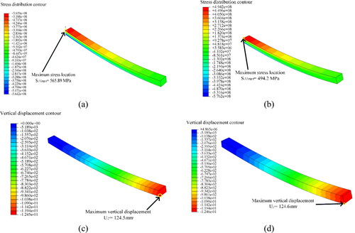
show the vertical deflection (U2) of carbon fiber/epoxy composite leaf spring without and with viscoelastic core under static load. As shown, the maximum deflection happens in the leaf spring with a viscoelastic core, which is124.6 mm. According to Hook’s low, the spring’s stiffness is 33.87 and 33.75 kN/m, higher than that of E-glass/epoxy composite leaf springs.
Subsequently, the dynamic response of the designed carbon fiber/epoxy composite under impact loading is investigated. The carbon fiber/epoxy composite leaf spring is subjected to an impact load of 4200 N and a static load of 4200 N, which is applied on the free end of the leaf spring
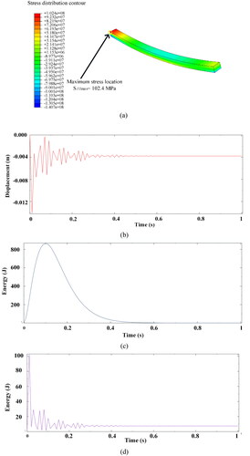
Dynamic analysis for carbon fiber/epoxy composite leaf spring without a viscoelastic core layer is reported. illustrates dynamic analysis results of carbon fiber/epoxy composite leaf spring without a viscoelastic core. presents the stress contour in the direction of fibers, displacement-time, kinetic energy, and strain energy curves of carbon fiber/epoxy composite leaf spring.
Figure 12. Dynamic results for carbon fiber/epoxy composite leaf spring without the viscoelastic core.
The impact response of carbon fiber/epoxy composite leaf spring with the viscoelastic core thickness of 2 mm is investigated in the present study (). The stress contour in the direction of fibers, displacement-time, kinetic energy, and strain energy curves of carbon fiber/epoxy composite leaf spring with a viscoelastic core thickness of 2 mm is presented in , respectively.
Figure 13. Dynamic results for carbon fiber/epoxy composite leaf spring with the viscoelastic core thickness of 2 mm.
shows the deflection-time curve in the vertical direction; after impact loading, the maximum deflection amplitude is 450 mm, higher than that for E-glass/epoxy. In order to gain a clear understanding of how the composite leaf spring responds to impact load, the damping ratio is determined according to EquationEqs. (3)(3)
(3) and Equation(4)
(4)
(4) as:
Therefore the system is underdamped. represents how kinetic energy change versus time. The vertical axis shows that the maximum kinetic energy is 2260 J approximately. The horizontal axis represents that it takes 0.8 s to leaf spring stabilization, which is higher than composite leaf spring without the viscoelastic core. shows the strain energy changes over time. The maximum strain energy is 170 J, which is higher than the E-glass/epoxy composite leaf spring with a viscoelastic thickness of 2 mm.
5.2. Effect of viscoelastic core on the dynamic response in composite leaf springs
In the present study, to gain a far better understanding of the viscoelastic layer’s effect, the dynamic response of all designed E-glass/epoxy composite leaf spring is presented in one graph in . All design results, such as the damping ratio for E-glass/epoxy composite leaf spring for three different viscoelastic core thicknesses, are listed in . According to , the damping ratio of all E-glass/epoxy composite leaf springs is less than 1 (δ < 1), so the system is underdamped. Furthermore, in this condition (δ < 1), as the damping ratio decreases, the passenger experiences a smooth ride, and the spring system absorbs the shocks and impact. indicates the displacement of free end versus time for four types of composite leaf springs. In this figure, CLS stands for composite leaf spring, and CVLS stands for composite viscoelastic leaf spring (with viscoelastic core). This graph presents that adding viscoelastic increases the vibration time. illustrates another important composite leaf spring feature, the strain energy versus time, for all designed springs.
Figure 14. Dynamic response of all designed E-glass/epoxy composite leaf spring.
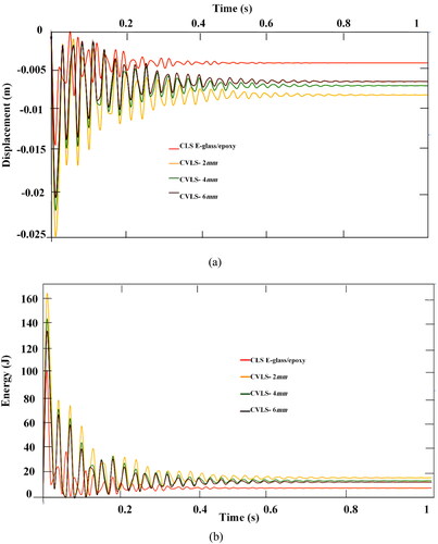
Table 8. Designed E-glass/epoxy composite leaf spring with and without viscoelastic core.
In , CLS stands for composite leaf springs without viscoelastic core, CVLS 2 mm, 4 mm, and 6 mm stands for composite leaf spring with the viscoelastic thickness of 2 mm, 4 mm, and 6 mm, respectively.
The area under strain energy curves shows the amount of strain energy stored by the composite leaf spring, listed in that reports that the E-glass/epoxy composite leaf spring with a viscoelastic core thickness of 2 mm stores the maximum strain energy. The strain energy capacity of the spring is a vital feature because the vibration in the vehicle induced by surface irregularities is stored in the spring as strain energy, then the spring releases slowly. The spring without a viscoelastic layer absorbs less strain energy.
Table 9. The strain energy capacity of E-glass /epoxy composite leaf spring.
Subsequently, the same analysis is done for carbon fiber/epoxy composite. shows the dynamic response of all designed carbon fiber/epoxy composite leaf spring. Furthermore, all design results, such as the damping ratio for Carbon/epoxy composite leaf spring for three different viscoelastic core thicknesses, are listed in . This graph presents that adding viscoelastic increases the vibration time. depicts the strain energy versus time for all designed springs. The area under strain energy curves, which is the amount of strain energy stored by the composite leaf spring, is listed in . Results show that similar to the E-glass/epoxy composite leaf spring, the carbon fiber/epoxy with a viscoelastic core thickness of 2 mm stores the maximum strain energy; also, the spring without a viscoelastic layer absorbs less strain energy.
Figure 15. Dynamic response of all designed carbon fiber/epoxy composite leaf spring.
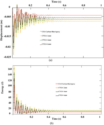
Table 10. Designed carbon fiber/epoxy composite leaf spring with and without viscoelastic cores.
Table 11. The strain energy capacity of carbon fiber/epoxy composite leaf spring.
Materials in the present study are selected from common materials used in industry, such as composite materials and viscoelastic core used for reducing damping in the industry. Furthermore, the model is verified with reliable references. Therefore, the designed composite leaf spring with a viscoelastic core could be reliable and provide new insight into fabricating novel composite leaf springs with a viscoelastic core to reduce undesirable vibrations in the vehicles. It is worth mentioning that in the present study, both E-glass/epoxy and carbon fiber/epoxy composite leaf spring, which are common types of composite leaf spring, are examined in which cope with demand.
6. Concluding remarks
In the present study, a 3D finite element analysis employing Abaqus is conducted to assess the influence of adding viscoelastic core on the post-impact behavior of the composite leaf spring. Results indicate that
Fabrication of composite leaf spring with viscoelastic core decreases the damping ratio of the leaf spring system, which results in a smooth ride since the spring system absorbs the shocks.
Composite leaf springs with viscoelastic core have stored more strain energy (strain energy capacity), which is a significant feature for the composite leaf spring.
Composite leaf springs with a viscoelastic core thickness of 2 mm are optimum leaf springs from the strain energy capacity point of view (in both types of composite leaf spring).
E-glass/epoxy composite leaf springs with a viscoelastic core thickness of 2 mm have more strain energy capacity than other composite leaf springs.
References
- Al-Qrimli, H. F., F. A. Mahdi, and F. B. Ismail. 2015. Carbon/epoxy woven composite experimental and numerical simulation to predict tensile performance. Advances in Materials Science and Applications 4 (2):33–41. doi:10.5963/AMSA0402001.
- Al-Qureshi, H. 2001. Automobile leaf springs from composite materials. Journal of Materials Processing Technology 118 (1–3):58–61. doi:10.1016/S0924-0136(01)00863-9.
- Alaimo, A.,. C. Orlando, and S. Valvano. 2019. Analytical frequency response solution for composite plates embedding viscoelastic layers. Aerospace Science and Technology 92:429–45. doi:10.1016/j.ast.2019.06.021.
- Alavi, S. H., and H. Eipakchi. 2019. Analytical method for free-damped vibration analysis of viscoelastic shear deformable annular plates made of functionally graded materials. Mechanics Based Design of Structures and Machines 47 (4):497–519. doi:10.1080/15397734.2019.1565499.
- Arikoglu, A., and I. Ozkol. 2010. Vibration analysis of composite sandwich beams with viscoelastic core by using differential transform method. Composite Structures 92 (12):3031–9. doi:10.1016/j.compstruct.2010.05.022.
- Cherruault, J.-Y., J. Hou, G. Jeronimidis, R. Mayer, and J. Chvojan. 2011. Testing of fiber composite leaf spring for heavy axle loads. Journal of Thermoplastic Composite Materials 24 (1):111–32. doi:10.1177/0892705709096552.
- Fasana, A., and S. Marchesiello. 2001. Rayleigh-Ritz analysis of sandwich beams. Journal of Sound and Vibration 241 (4):643–52. doi:10.1006/jsvi.2000.3311.
- Felippe Filho, W. N., F. d S. Barbosa, N. Roitman, C. Magluta, and F. C. Borges. 2017. Experimental and numerical evaluation of viscoelastic sandwich beams. REM - International Engineering Journal 70 (3):281–7. doi:10.1590/0370-44672013700015.
- Filippi, M., E. Carrera, and S. Valvano. 2018. Analysis of multilayered structures embedding viscoelastic layers by higher-order, and zig-zag plate elements. Composites Part B: Engineering 154:77–89. doi:10.1016/j.compositesb.2018.07.054.
- Gebremeskel, M. S. A. 2013. Design, simulation, and prototyping of single composite leaf spring for light weight vehicle. Global Journal of Research in Engineering 12 (7-A):21–30.
- Hou, J. P., J. Y. Cherruault, I. Nairne, G. Jeronimidis, and R. Mayer. 2007. Evolution of the eye-end design of a composite leaf spring for heavy axle loads. Composite Structures 78 (3):351–8. doi:10.1016/j.compstruct.2005.10.008.
- Johnson, C. D., and D. A. Kienholz. 1982. Finite element prediction of damping in structures with constrained viscoelastic layers. AIAA Journal 20 (9):1284–90. doi:10.2514/3.51190.
- Kumar, M. S., and S. Vijayarangan. 2007a. Analytical and experimental studies on fatigue life prediction of steel and composite multi-leaf spring for light passenger vehicles using life data analysis. Materials Science 13 (2):141–6.
- Kumar, M. S., and S. Vijayarangan. 2007b. Static analysis and fatigue life prediction of steel and composite leaf spring for light passenger vehicles. Journal of Scientific and Industrial Research 66:128–34.
- Mace, M. 1994. Damping of beam vibrations by means of a thin constrained viscoelastic layer: Evaluation of a new theory. Journal of Sound and Vibration 172 (5):577–91.
- Mead, D., and S. Markus. 1969. The forced vibration of a three-layer, damped sandwich beam with arbitrary boundary conditions. Journal of Sound and Vibration 10 (2):163–75. doi:10.1016/0022-460X(69)90193-X.
- Oztoprak, N., M. D. Gunes, M. Tanoglu, E. Aktas, O. O. Egilmez, C. Senocak, and G. Kulac. 2018. Developing polymer composite-based leaf spring systems for automotive industry. Science and Engineering of Composite Materials 25 (6):1167–76. doi:10.1515/secm-2016-0335.
- Pederson, J. 2008. Finite element analysis of carbon fiber composite ripping using ABAQUS. Thesis, Clemson University.
- Polach, P., and M. Hajžman. 2011. Computer simulations of the freight wagon laboratory excitation. Mechanics Based Design of Structures and Machines 39 (2):194–209. doi:10.1080/15397734.2011.550856.
- Praharaj, R., and N. Datta. 2020. Dynamic response spectra of fractionally damped viscoelastic beams subjected to moving load. Mechanics Based Design of Structures and Machines. doi:10.1080/15397734.2020.1725563.
- Rajendran, I., and S. Vijayarangan. 2001. Optimal design of a composite leaf spring using genetic algorithms. Computers & Structures 79 (11):1121–9. doi:10.1016/S0045-7949(00)00174-7.
- Rajesh, S., G. Bhaskar, J. Venkatachalam, K. Pazhanivel, and S. Sagadevan. 2016. Performance of leaf springs made of composite material subjected to low frequency impact loading. Journal of Mechanical Science and Technology 30 (9):4291–8. doi:10.1007/s12206-016-0842-x.
- Sancaktar, E., and M. Gratton. 1999. Design, analysis, and optimization of composite leaf springs for light vehicle applications. Composite Structures 44 (2–3):195–204. doi:10.1016/S0263-8223(98)00136-6.
- Shi, W., C. Qian, Q. Song, B. Gao, and J. Ke. 2017. Damping Analysis and Test Research of a Composite Leaf Spring in a Light Bus. Singapore: Springer Singapore.
- Shi, Y., H. Sol, and H. Hua. 2006. Material parameter identification of sandwich beams by an inverse method. Journal of Sound and Vibration 290 (3–5):1234–55. doi:10.1016/j.jsv.2005.05.026.
- Shokrieh, M. M., and D. Rezaei. 2003. Analysis and optimization of a composite leaf spring. Composite Structures 60 (3):317–25. doi:10.1016/S0263-8223(02)00349-5.
- Slanik, M. L., J. A. Nemes, M.-J. Potvin, and J.-C. Piedboeuf. 2000. Time domain finite element simulations of damped multilayered beams using a prony series representation. Mechanics of Time-Dependent Materials 4 (3):211–30. doi:10.1023/A:1009826923983.
- Song, Y., D. Sun, X. Zhang, X. Zhang, and Q. Shi. 2009. Dynamic modeling study on contact-type viscoelastic suspensions used in crawler construction vehicles. Mechanics Based Design of Structures and Machines 37 (4):513–37. doi:10.1080/15397730903256635.
- Thomson, W. 2018. Theory of vibration with applications. Boca Raton, FL: CRC Press.
- Valvano, S., A. Alaimo, and C. Orlando. 2019. Sound transmission analysis of viscoelastic composite multilayered shells structures. Aerospace 6 (6):69. doi:10.3390/aerospace6060069.
- Valvano, S., A. Alaimo, and C. Orlando. 2020. Analytical analysis of sound transmission in passive damped multilayered shells. Composite Structures 253:112742. doi:10.1016/j.compstruct.2020.112742.
- Valvano, S., C. Orlando, and A. Alaimo. 2019. Design of a noise reduction passive control system based on viscoelastic multilayered plate using PDSO. Mechanical Systems and Signal Processing 123:153–73. doi:10.1016/j.ymssp.2019.01.011.
- Yang, S., W. Shi, Z. Chen, C. Qian, C. Yang, and L. Hang. 2019. Composite mechanics and energy method based stiffness prediction model for composite leaf springs. Mechanics Based Design of Structures and Machines 47 (3):375–86. doi:10.1080/15397734.2018.1559738.
- Yousefi, A., M. Mosavi Mashhadi, and M. Safarabadi. 2020. Numerical analysis of cracked aluminum plate repaired with multi-scale reinforcement composite patches. Journal of Composite Materials 54 (28):4341–57. doi:10.1177/0021998320931177.