
 ?Mathematical formulae have been encoded as MathML and are displayed in this HTML version using MathJax in order to improve their display. Uncheck the box to turn MathJax off. This feature requires Javascript. Click on a formula to zoom.
Abstract
The three-dimensional bending behavior of a viscoelastic functionally graded material (FGM) layer embedded between piezoelectric layers and subjected to an electric field as well as a uniform transverse pressure is studied. An analytical solution is computed for a simply supported viscoelastic smart FGM plate using the state space technique along the thickness direction and a Fourier expansion along the in-plane coordinates. The governing differential equations in the time domain are transformed to the Laplace domain, solved in the Laplace domain, and transformed back to the time domain using the inverse Laplace transform. In the present study, the relaxation modulus of the FGM layer is assumed in the form of a Prony series, and it varies according to the power law in the thickness direction. The validity of the proposed approach is assessed by comparison of the numerical results of the approach with those of published works in the literature. The effects of geometric dimensions, electromechanical loads, and relaxation time constant on the behavior of the smart plate are investigated.
Introduction
Functionally graded materials (FGMs) represent specific types of composite materials whose properties vary gradually along a specific spatial direction as a result of their non-uniform microstructures with continuously graded macro-properties (Apalak and Demirbas Citation2019). The resistance of FGMs in high temperatures as a thermal barrier makes them a desirable option in environments such as rocket engines and space bodies (Marin Citation2005).
Brischetto et al. (Citation2008) used Extending Unified Formulation introduced by Carrera to investigate deformations of a simply supported, functionally graded, rectangular plate subjected to thermo- mechanical loadings using Fourier series solution. Based on Carrera Unified Formulation (CUF), Bharati et al. (Citation2020) analyzed flutter of a laminated composite structures under aerodynamics loading conditions using the principle of virtual displacement along with finite element method. Stress distributions in the geometrical nonlinear regime of functionally graded structures was evaluated by Demirbas et al. (Citation2020) in the framework of CUF employing Newton-Raphson technique as well as Finite Element Method. Based on higher order shear deformation theory, Sahoo et al. (Citation2020) developed an eigenvalue-based approach to predict the critical buckling temperature of graded sandwich structures. Sahoo et al. (Citation2021) studied numerically thermal eigenvalue responses of a functionally graded sandwich shell structure. Effect of grading pattern and porosity on the eigen characteristics of porous functionally graded structure was studied by Ramteke et al. (Citation2019) using isoparametric finite element technique. Ramteke et al. (Citation2020) carried out static analysis of a two directional graded structure using a commercial FE method. Bending behavior of a functionally graded structure with variable grading patterns as well as variable porosity was studied by Ramteke et al. (Citation2021) using finite element method.
At elevated temperatures, some materials, including the FGMs, tend to have creep and relaxation behaviors, which necessitates the incorporation of the theory of viscoelasticity, in which the time-dependent response cannot be considered negligible because of their viscoelastic behavior (Lakes and Lakes Citation2009). Widespread applications of FGMs in high-temperature environments causes a viscoelastic constitutive model to be more accurate compared with an elastic model when it comes to the analysis of such materials used in practical applications. Exhibiting electromechanical coupling effects between the electric field and the elastic deformation, piezoelectric materials combined with FGMs represent a smart or intelligent system. Piezoelectric layers, used as actuator and sensor layers, enable the system to respond to changing operating environments. Liew et al. (Citation2001) investigated the three-dimensional transient response in FG rectangular plates equipped with piezoelectric layers. Phung-Van et al. (Citation2013) used a Mindlin plate theory to study the static and dynamic behavior of laminated plates with piezoelectric layers. Khalili, Malekzadeh, and Mittal (Citation2005) analyzed the static and dynamic behavior of a simply supported plate using the Fourier series technique and Stokes’s transformation. Vel and Batra (Citation2000) investigated the bending behavior of rectangular laminated piezoelectric plates analytically using the Eshelby-Stroh formalism. Mitchell and Reddy (Citation1995) developed a refined theory of laminated composite plates with piezoelectric laminae within the framework of linear piezoelectricity, in which they included the coupling between mechanical deformations and the charge equations of electrostatics. Fernandes and Pouget (Citation2001) presented an efficient two-dimensional approach for piezoelectric plates in the framework of the linear theory of piezoelectricity using a variational method. Based on higher-order shear deformation theory and using the principle of virtual displacements, Khetib et al. (Citation2019) studied the vibration behavior of an FGM plate resting on a viscoelastic Winkler-Pasternak foundation. Based on concepts of Boltzmann and Volterra, Sofiyev, Zerin, and Kuruoglu (Citation2020) investigated free vibrations and the dynamic stability of an FGM viscoelastic plate under a compressive load and resting on elastic foundations using the Galerkin and Laplace integral transform. Buckling and free vibration analysis of sandwich plates with a viscoelastic core and FGM face sheets under high-temperature environment were carried out by Joseph and Mohanty (Citation2019) in the framework of first-order shear deformation theory using the finite element method. Shokrgozar et al. (Citation2020) studied, analytically and numerically, bending behavior of cylindrical microshell rested on viscoelastic foundation using Fourier series state-space technique and generalized differential quadrature method (GDQM).
Despite the fact that the analytical solutions are well accepted in the engineering domain, for cases such as viscoelastic structures in which the governing equations are hard to be handled analytically due to the structure shape and complex boundary conditions, the numerical solutions would be adopted (Sahoo et al. Citation2020). Norouzi and Alibeigloo (Citation2016, Citation2018) investigated the three-dimensional bending behavior of a viscoelastic FGM cylindrical panel subjected to thermal or mechanical loads using a combined state space and Laplace transform approach. Active vibration control of FGM plates with integrated piezoelectric sensors and actuators in a thermal environment was studied using the finite element method in He et al. (Citation2001) and Liew et al. (Citation2003). Jermsittiparsert et al. (Citation2020) used GDQ to investigate buckling, critical voltage, and vibration response of a thermally affected graphene nanoplatelet reinforced composite (GPLRC) micro disk coupled with a piezoelectric actuator.
Based on Reddy’s higher-order shear deformation plate theory, Yang, Kitipornchai, and Liew (Citation2003) investigated the vibration behavior of FGM plates with integrated piezoelectric layers in a thermal environment using a one-dimensional differential quadrature and a Galerkin technique. Tekin and Kadıoğlu (Citation2017) developed a mixed-type finite element model as well as a corresponding functional in the Laplace–Carson domain to analysis of quasi-static and dynamic behavior of viscoelastic Kirchhoff plates. They used Dubner and Abate numerical inverse Laplace to convert the solution to time domain. Paulino and Jin (Citation2001) used the viscoelastic correspondence principle and the finite element method to simulate viscoelastic FGMs subjected to mechanical and thermal loads. Thermoelastic buckling and vibration analysis of an FGM sandwich beam with a constrained viscoelastic core was performed by Bhangale and Ganesan (Citation2006) using the finite element method. To study the generalized theories of magneto-thermo-viscoelasticity, a rotating FGM plate was modeled numerically using the dual reciprocity boundary element method in Fahmy (Citation2013).
Based on modified couple stress theory, vibration and stability analysis of a viscoelastic micro-shell conveying fluid in thermal environment was carried out by Rashvand, Alibeigloo, and Safarpour (Citation2020). Safarpour, Rahimi, and Alibeigloo (Citation2020) studied graphene reinforced composite truncated conical shells, cylindrical shells and annular plates sem-analytically using state space DQM. Three-dimensional bending and free vibration analysis of laminated composite plates regarding the effects of a viscoelastic interface was conducted by Alibeigloo (Citation2015) using a state-space technique as well as Laplace transform.
The governing equations based on three-dimensional theory of elasticity are exact due to no simplifying assumptions in the extraction process of the equations. So, solutions of those equations can be used to assess the validity of results based on approximate conventional two-dimensional formulation. Moreover, in theory of elasticity, transverse normal and shear stresses which cause delamination and crack initiation at the interface of multi layered structures are determined exactly. Therefore, in this paper we use elasticity formulation to investigate, analytically, bending behavior of viscoelastic smart structures under electromechanical loads that has not yet been reported in literature.
The viscoelastic constitutive equations are expressed using the Boltzmann superposition principle, while the material properties of the FGM layer are assumed to vary in the thickness direction according to a power law. We use Fourier series approach along the in-plane coordinates and state-space technique across the thickness direction for space domain and Laplace transform for time domain.
Mathematical formulation
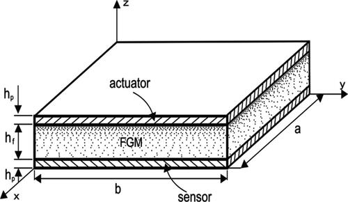
A simply supported sandwich rectangular plate with the geometry as shown in is studied. The sandwich plate consists of three layers, namely, the top piezoelectric layer as the actuator, a viscoelastic FGM core layer in the middle, and the bottom piezoelectric layer as the sensor. and
are the length and width of the plate along
and
directions, respectively, and the thickness of the total plate is
the origin of the coordinate system is located on the bottom of the plate. The plate is subjected to the uniform pressure,
on the top surface as well as the electric voltage,
at the top surface of the piezoelectric layer.
Figure 1. Sandwich plate with FGM layer sandwiched between two piezoelectric layers.
Three-dimensional governing equilibrium equations in the absence of body force are as follows:
(1)
(1)
Most materials, which respond elastically at room temperature, tend to exhibit significant viscoelastic behavior at an elevated temperature. Since FGMs are usually used in high-temperature environments, one must consider viscoelasticity in order to capture the actual material behavior (Alibeigloo Citation2015). For linear viscoelastic materials, the three-dimensional constitutive relations can be represented by the Boltzmann superposition principle as Li et al. (Citation2019) and Norouzi and Alibeigloo (Citation2016),
(2)
(2)
where
represents normal stresses,
and
represents shear stresses,
and
And similarly,
represents normal strains,
and
represents shear strains,
and
represents relaxation moduli coefficients, which depend on time in viscoelastic materials, defined in EquationEq. (A-1)
(1)
(1) .
FGM layer
Formulation in Laplace domain
A set of integro-differential equations in the time domain is derived by substitution of EquationEq. (2)(2)
(2) into EquationEq. (1)
(1)
(1) . To avoid the complexities accompanied with the solution of those equations, before the implementation, EquationEq. (2)
(2)
(2) is transformed into the Laplace domain by using Laplace transform (Norouzi and Alibeigloo Citation2018):
(3)
(3)
where the caret over each variable indicates the Laplace transformation of the variable.
Assuming a constant Poisson ratio, the linear viscoelastic constitutive relation in term of displacement components for FGM layer of the plate is expressed as
(4)
(4)
here
indicates the FGM layer.
From EquationEqs. (1)(1)
(1) , Equation(3)
(3)
(3) , and Equation(4)
(4)
(4) , state-space governing differential equations in matrix form are derived as:
(5)
(5)
where
are the state variables and
is the square coefficient matrix, defined in EquationEq. (A-2).
Additionally, induced variables (in-plane stresses) can be written in terms of the state variables as follow:
(6)
(6)
In the time domain, the relaxation modulus, of the FGM layer is assumed in the form of a Prony series (Norouzi and Alibeigloo Citation2018),
(7)
(7)
in which
and
The subscripts and
refer to metal and ceramic constituents in the FGM layer, which could be copper and tungsten or aluminum and alumina (Norouzi and Alibeigloo Citation2018).
denotes the relaxation time constant, which is considered identical for the two constituents.
Piezoelectric layer
Both piezoelectric layers are assumed to exhibit linear piezoelastic material behavior; in particular, we only concern ourselves with orthorhombic piezoelectric materials of crystal class 2 mm, used for the actuator layers; and with tetragonal piezoelectric materials of crystal class 4 mm, for which the plane of the layer is the isotropic, used for the sensor layer. In these cases, the constitutive relations can be written as:
(8)
(8)
where
and
are defined in EquationEqs. (A-3)–(A-5).
The equilibrium equations, in the absence of body forces, are as
(9)
(9)
And, for the non-conducting piezoelectric layers, we also have the conservation of electrical charges
(10)
(10)
The relations between the electric field and electric potential are
(11)
(11)
At the upper surface of the actuator and the lower surface of the sensor, there are the following mechanical and electrical surface boundary conditions:
(12)
(12)
Moreover, at the interfaces of the actuator and sensor with the viscoelastic layers, electric potential, is also zero.
At the boundaries, for a simply supported plate, the following conditions are satisfied:
(13)
(13)
Combining EquationEqs. (8)–(13), similar to the FGM layer, constitutive equations for the piezoelectric layers in terms of displacement components are derived; and with the similar manipulation, the following state-space governing equation in Laplace domain for the piezoelectric layers is yielded.
(14)
(14)
where
is a constant coefficient square matrix, defined in EquationEq. (A-6)
(A-6)
(A-6) .
Solution procedure
FGM layer
Relations for simply supported boundary conditions of the rectangular plate are
(15)
(15)
The following Fourier series expansions for stress and the displacement components satisfy simply supported boundary conditions relation, EquationEq. (15)(15)
(15)
(16)
(16)
For convenience, the following non-dimensional quantities are introduced:
(17)
(17)
Here is the scale factor and
is the applied mechanical load.
Then, we derive a non-dimensional version of the state-space formulation introduced in EquationEq. (5)(5)
(5) for the non-dimensional expansion coefficients of the Fourier series as
(18)
(18)
where
is the non-dimensional square matrix of coefficients, defined in EquationEq. (A-7)
(A-7)
(A-7) .
Also, the non-dimensional state variables can be used to derive the non-dimensional induced variables:
(19)
(19)
where
is a coefficient matrix, defined in EquationEq. (A-8)
(8)
(8) .
Since the transfer matric is not constant because of the variation of the material properties along the thickness direction, we employ a layer-wise approximation dividing the FGM layer into
fictitious thin layers whose material parameters are assumed constant along the z-direction; hence, the full transfer matrix for the fictitious layers
can be considered constant in each fictitious layer,
leading to the following solution to EquationEq. (18)
(18)
(18)
(20)
(20)
in which
Then EquationEq. (13)(13)
(13) at
becomes
(21)
(21)
where
Regarding the continuity condition of the state variables at the interface of each two adjacent fictitious layers, state variables at the top and the bottom surfaces of the viscoelastic layer are related as follows:
(22)
(22)
where
and
are the state vector at the bottom and top surfaces of the viscoelastic layer, respectively.
Piezoelectric layer
The following dimensionless quantities are defined for the piezoelectric layers:
(23)
(23)
In addition to the Fourier series solution used in EquationEq. (17)(17)
(17) , the following series expansion are used for simply supported boundary conditions in the piezoelectric layer:
(24)
(24)
By substituting EquationEqs. (16)(16)
(16) , Equation(23)
(23)
(23) , and Equation(24)
(24)
(24) into EquationEq. (18)
(18)
(18) , the following non-dimensional state-space equation in matrix form for the piezoelectric layers is derived:
(25-a)
(25-a)
where
the matrix
is defined in EquationEq. (A-9). In term of state variables, the induced variables for the piezoelectric layers can be derived as follow:
(25-b)
(25-b)
where
is the coefficient matrix, defined in EquationEq. (A-10).
In the sensor and actuator layers with simply supported boundary conditions, the general solution for EquationEq. (25(25-a)
(25-a) -a), respectively, are
(26-a)
(26-a)
(26-b)
(26-b)
EquationEquations (26(26-a)
(26-a) -a) and (26-b) at the above surfaces of actuator and sensor layers are, respectively,
(27-a)
(27-a)
(27-b)
(27-b)
where
Based on Eq. (27a), at the lower surface of the actuator layer, electric displacement is (Feri, Alibeigloo, and Pasha Zanoosi, Citation2016):
(28)
(28)
where
are the
row and
column elements of matrix
and
is the mechanical part of the state variables of the actuator at its interface with the viscoelastic layer,
inserting EquationEq. (27
(27-a)
(27-a) -b) and relation
into EquationEq. (26
(26-a)
(26-a) -a) yields:
(29)
(29)
where
With the aid of Eq. (27b), at the lower surface of the sensor, the electric potential, can be derived as:
(30)
(30)
Setting and substituting EquationEq. (30)
(30)
(30) into EquationEq. (27
(27-a)
(27-a) -b) results in
(31)
(31)
where
Because the mechanical tractions and displacements at the interfaces of the actuator, FGM, and sensor are continuous, using EquationEqs. (22)(22)
(22) , Equation(29)
(29)
(29) , and Equation(31)
(31)
(31) , the relationship between the mechanical state variables at the top and bottom surfaces of the plate follows as:
(32)
(32)
where
EquationEquation (32)(32)
(32) reduces to the following form by using surface traction at the bottom and top surfaces of the plate.
(33)
(33)
From EquationEq. (33)(33)
(33) , displacements,
at the lower surface in the sensor can be obtained; then using EquationEqs. (20)
(20)
(20) , (26-a) and (26-b) leads to determine mechanical and electrical state variables in three dimensions. Finally, to invert Laplace transforms of the states, modified Dubner’s and Abats’s numerical techniques are utilized to represent displacement and stress fields in the time domain (Abate and Whitt Citation1995).
Numerical results
A simply-supported square FGM plate with viscoelastic behavior sandwiched between two piezoelectric layers is considered. The material properties of the two piezoelectric layers are given in (Alibeigloo Citation2010). The relaxation time constant is the Poison ratio is
and the parameters for the Prony series, related to EquationEq. (7)
(7)
(7) , as in Norouzi and Alibeigloo (Citation2018) are
Table 1. Material properties of piezoelectric sensor and actuator (Alibeigloo Citation2010).
It is noted that all presented results are their maximum value which are computed at The values of the other parameters involved in the plate are as follows unless the effects of variation of those parameters are studies.
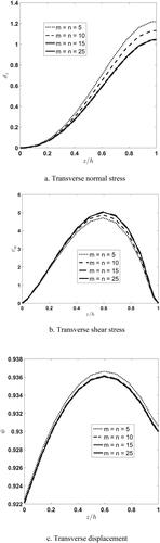
First, we study the convergence of the solution. We consider the length-to-thickness ratio as and the total thickness to piezoelectric layer thickness ratio as
The actuator is operated in a short circuit condition and only the uniform pressure
is applied. The through-the-thickness distribution of the non-dimensional deflection, transverse normal stress, and transverse shear stress in the center of the plate are shown in for various half wave numbers (
) with 15 fictitious layers for the FGM core. From the figures, one can see that increasing the half wave numbers up to
increases the transverse normal stress and the deflection while it decreases the transverse shear stress; all three entities are converged, which indicates fast convergence with respect to the half wave numbers (
). Next, we keep
fixed and study the convergence with respect to the number of fictitious layers for the FGM core.
Figure 2. Distribution of transverse normal stress, shear stress, and deflection along the thickness direction for different half wave numbers (m, n), using 15 fictitious layers for the FGM core layer.
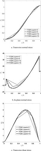
Next, for validation of the present approach, an elastic square FGM plate under mechanical load, which is utilized in Brischetto et al. (Citation2008), is adopted. Dimensionless stress and displacement components in the in-plane center of the plate at the bottom (), top (
) and mid surface (
) of the plate is computed and compared with those reported in Brischetto et al. (Citation2008). We use
and
fictitious layers. The results are presented in . According to , the present results are in good agreement with the results reported in Brischetto et al. (Citation2008). The minor discrepancy is due to the CFU formulation which has been used in this reference.
Table 2. Comparison of stresses and displacements of an elastic square FGM plate under a mechanical load.
The convergence of through-thickness distribution of transverse normal and shear stresses and deflection by increase in the number of fictitious layers is computed and depicted in . From the figures, it can be observed that the effect of increase in the number of mathematical layers on deflection is more significant. Moreover, it is seen that with 15 fictitious layers, all entities converge to constant values. It is noted that all of the upcoming results are based on this value for the mathematical layers.
Figure 3. Through-the-thickness distribution of the non-dimensional transverse normal stress, inplane normal stress, and transverse shear stress for different numbers of mathematical layers for the FGM core.
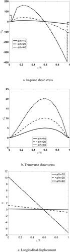
In the following results, we use and
fictitious layers. The effect of the length-to-thickness ratio
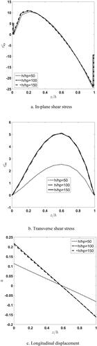
on the through-the-thickness distribution of dimensionless stresses and longitudinal displacement of the viscoelastic FGM plate are depicted in . One can see that an increase in the
value causes the stiffness of the plate to decrease and consequently the stresses and the displacement to increase. Moreover, it is observed that continuity of the in-plane displacement and transverse shear stress at the interface of the FGM core and piezoelectric layer is satisfied. As expected, continuity of the in-plane shear stress at the interfaces is not satisfied. Additionally, it can be seen that the effect of variation in
on
is more significant near the top surface of the plate, whereas for the in-plane displacement this is the case near the bottom surface of the plate. Since the neutral surface in FGM core does not coincide with the mid surface, the maximum value of transverse shear stress is not located in the thickness center of the plate but shifted toward the top.
Figure 4. Effect of length to thickness ratio, a/h, on through-thickness distribution of nondimensional in-plane and transverse shear stresses and longitudinal displacement.
Effect of piezoelectric layer thickness on stress and displacement components in the absence of applied electric voltage are depicted in . According to the figures, in the absence of electric voltage, decreasing the piezoelectric layers thickness ratio up to causes the mechanical behavior of the viscoelastic FGM plate to converge to a constant value.
Figure 5. Effect of piezoelectric thick on distribution of non-dimensional in-plane and transverse shear stresses and longitudinal displacement.
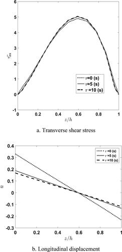
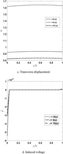
represents the distribution of stress, displacements, and induced electric voltage of viscoelastic FGM plate with different relaxation time constant, According to the figures, the displacements and electric voltage in the elastic plate are greater than those for the viscoelastic plate. Moreover, it is seen that in elastic FGM plate transverse shear stress near the mid surface is smaller and near the bottom and top surfaces is greater than that for the viscoelastic plate. Also, it can be observed that the increase causes the displacements and electric voltage to decrease.
Figure 6. Effect of time constant variation, τ, on the through-thickness distribution of nondimensional transverse shear stress, longitudinal and transverse displacements, and induced voltage.
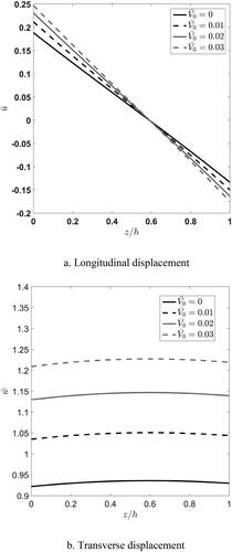
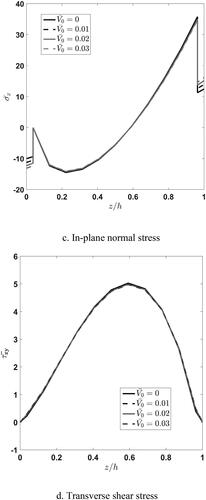
Effect of applied voltage, on the through-thickness distribution of longitudinal and transverse displacements of the square plate is depicted in . According to , voltage increase causes longitudinal displacement in both FGM and piezoelectric layers to increase linearly. From , it is seen that the increased voltage causes the deflection nonlinearly in the FGM layer to increase whereas it is linear in piezoelectric. Additionally, it is concluded that effect of applied voltage on deflection is more significant than that for the longitudinal displacement.
Figure 7. Influence applied voltage variation on the through-thickness distribution of nondimensional longitudinal and transverse displacements, in-plane normal stress, and transverse shear stress.
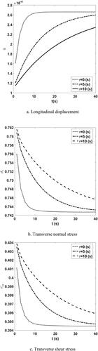
Displacement and stress distributions versus time with different relaxation time constants are shown in . According to the figures and as expected, stresses and displacement convergence toward a specified value. Additionally, it is concluded that an increase in the relaxation time constant causes the convergence time to increase. Also, it is seen that increasing relaxation time constant at each time causes the displacements to decrease and the stress to increase.
Figure 8. Time history of longitudinal displacement, transverse normal and shear stresses at the height of for different time constants.
depicts dimensionless stresses and displacements for a thick, moderately thick and thin viscoelastic rectangular FGM plate embedded with piezoelectric layers, with different relaxation time constants. Regardless of relaxation time constant, increase in the length to thickness ratio, causes an increase in the displacement and stress components. From , it can be seen that increase relaxation time constant causes to increase stresses whereas displacements decrease. Moreover, it is concluded that effect of relaxation time constant in thin plate is more significant.
Table 3. Maximum stresses and displacements of the sandwich FGM plate in elastic () and viscoelastic (
) cases for different
ratio.
Conclusion
In the present paper, a three-dimensional static analysis of an FGM viscoelastic plate sandwiched between two piezoelectric layers and subjected to electromechanical loading was conducted within the framework of linearized three-dimensional viscoelasticity. The analytical solution was computed by applying a state-space approach through the thickness direction and a Fourier series approach for the in-plane problem. The governing state-space equations were solved in the Laplace domain and the response in the time domain was obtained using the inverse Laplace transform. Based on the numerical results, it was demonstrated that the viscoelastic properties strongly affect the bending behavior of the FGM plate and the following conclusions were derived:
Mechanical displacements and electric voltage in the purely elastic plate are larger whereas the stresses are smaller than those for the viscoelastic plate.
Increase of the relaxation time constant causes the displacements, the induced electric voltage, and the stresses to increase.
The rate of convergence to elastic behavior decreases with increasing relaxation time constant.
In the viscoelastic plate, the effect of the relaxation time constant increases with increasing length-to-thickness ratio.
The effect of the applied voltage on the deflection compared to the in-plane displacements is more significant.
The through-the-thickness distribution of the deflection due to an applied voltage is nonlinear whereas it is linear in the piezoelectric layers.
The effect of increasing length-to-thickness ratio on the behavior of the viscoelastic plate more pronounced than that for the elastic plate.
| Nomenclature | ||
| a, b, h | = | plate dimensions in x-, y- and z-directions |
| = | relaxation moduli coefficients | |
| = | electric displacement | |
| = | electric field in x-, y- and z-directions | |
| = | Young’s modulus | |
| = | piezoelectric constants and dielectric constants | |
| = | piezoelectric modulus | |
| = | thicknesses of the FGM and piezoelectric layers | |
| = | half wave numbers in the x-, y- and z-directions | |
| = | displacement components in the x-, y- and z-directions | |
| = | normal stresses | |
| = | shear stresses | |
| = | normal strains | |
| = | shear strains | |
| = | relaxation time constant | |
| = | state vectors of the FGM and piezoelectric layers | |
| = | electric voltage | |
| = | Poison ratio | |
Acknowledgment
The authors acknowledge the TU Wien Bibliothek for financial support through its Open Access Funding Program.
References
- Abate, J., and W. Whitt. 1995. Numerical inversion of Laplace transforms of probability distributions. ORSA Journal on Computing 7 (1):36–43. doi:10.1287/ijoc.7.1.36.
- Alibeigloo, A. 2010. Thermo-elasticity solution of functionally graded plates integrated with piezoelectric sensor and actuator layers. Journal of Thermal Stresses 33 (8):754–74. doi:10.1080/01495739.2010.482350.
- Alibeigloo, A. 2015. Effect of viscoelastic interface on three-dimensional static and vibration behavior of laminated composite plate. Composites Part B: Engineering 75:17–28. doi:10.1016/j.compositesb.2015.01.025.
- Apalak, M. K., and M. D. Demirbas. 2019. Improved mathematical models of thermal residual stresses in functionally graded adhesively bonded joints: A critical review. Reviews of Adhesion and Adhesives 7 (4):367–416. doi:10.7569/RAA.2019.097313.
- Bhangale, R. K., and N. Ganesan. 2006. Thermoelastic buckling and vibration behavior of a functionally graded sandwich beam with constrained viscoelastic core. Journal of Sound and Vibration 295 (1–2):294–316. doi:10.1016/j.jsv.2006.01.026.
- Bharati, R. B., M. Filippi, P. K. Mahato, and E. Carrera. 2020. Flutter analysis of laminated composite structures using Carrera Unified Formulation. Composite Structures 253:112759. doi:10.1016/j.compstruct.2020.112759.
- Brischetto, S., R. Leetsch, E. Carrera, T. Wallmersperger, and B. Kröplin. 2008. Thermo-mechanical bending of functionally graded plates. Journal of Thermal Stresses 31 (3):286–308. doi:10.1080/01495730701876775.
- Demirbas, M. D., X. Xu, E. Carrera, H. Yang, and R. Augello. 2020. Evaluation of stress distributions in the geometrical nonlinear regime of functionally graded structures. Composite Structures 246:112385. doi:10.1016/j.compstruct.2020.112385.
- Fahmy, M. A. 2013. Generalized magneto-thermo-viscoelastic problems of rotating functionally graded anisotropic plates by the dual reciprocity boundary element method. Journal of Thermal Stresses 36 (3):284–303. doi:10.1080/01495739.2013.765206.
- Feri, M., Alibeigloo, A., and A. A. Pasha Zanoosi. 2016. Three dimensional static and free vibration analysis of cross-ply laminated plate bonded with piezoelectric layers using differential quadrature method. Meccanica 51 (4):921–37. doi:10.1007/s11012-015-0246-5.
- Fernandes, A., and J. Pouget. 2001. Accurate modelling of piezoelectric plates: Single-layered plate. Archive of Applied Mechanics (Ingenieur Archiv) 71 (8):509–24. doi:10.1007/s004190100168.
- He, X. Q., T. Y. Ng, S. Sivashanker, and K. M. Liew. 2001. Active control of FGM plates with integrated piezoelectric sensors and actuators. International Journal of Solids and Structures 38 (9):1641–55. doi:10.1016/S0020-7683(00)00050-0.
- Jermsittiparsert, K., A. Ghabussi, A. Forooghi, A. Shavalipour, M. Habibi, D. Won Jung, and M. Safa. 2020. Critical voltage, thermal buckling and frequency characteristics of a thermally affected GPL reinforced composite microdisk covered with piezoelectric actuator. Mechanics Based Design of Structures and Machines :1–23. doi:10.1080/15397734.2020.1748052.
- Joseph, S. V., and S. C. Mohanty. 2019. Temperature effects on buckling and vibration characteristics of sandwich plate with viscoelastic core and functionally graded material constraining layer. Journal of Sandwich Structures & Materials 21 (4):1557–77. doi:10.1177/1099636217722309.
- Khalili, M. R., K. Malekzadeh, and R. K. Mittal. 2005. A new approach to static and dynamic analysis of composite plates with different boundary conditions. Composite Structures 69 (2):149–55. doi:10.1016/j.compstruct.2004.06.006.
- Khetib, M., H. Abbad, N. Elmeiche, and I. Mechab. 2019. Effect of the viscoelastic foundations on the free vibration of functionally graded plates. International Journal of Structural Stability and Dynamics 19 (11):1950136. doi:10.1142/S0219455419501360.
- Lakes, R., and R. S. Lakes. 2009. Viscoelastic materials. New York, NY: Cambridge University Press.
- Li, C., H. Guo, X. Tian, and T. He. 2019. Generalized thermoviscoelastic analysis with fractional order strain in a thick viscoelastic plate of infinite extent. Journal of Thermal Stresses 42 (8):1051–70. doi:10.1080/01495739.2019.1587331.
- Liew, K. M., X. Q. He, T. Y. Ng, and S. Sivashanker. 2001. Active control of FGM plates subjected to a temperature gradient: Modelling via finite element method based on FSDT. International Journal for Numerical Methods in Engineering 52 (11):1253–71. doi:10.1002/nme.252.
- Liew, K. M., X. Q. He, T. Y. Ng, and S. Kitipornchai. 2003. Finite element piezothermoelasticity analysis and the active control of FGM plates with integrated piezoelectric sensors and actuators. Computational Mechanics 31 (3):350–8. doi:10.1007/s00466-003-0437-0.
- Marin, L. 2005. Numerical solution of the Cauchy problem for steady-state heat transfer in two-dimensional functionally graded materials. International Journal of Solids and Structures 42 (15):4338–51. doi:10.1016/j.ijsolstr.2005.01.005.
- Mitchell, J. A., and J. N. Reddy. 1995. A refined hybrid plate theory for composite laminates with piezoelectric laminae. International Journal of Solids and Structures 32 (16):2345–67. doi:10.1016/0020-7683(94)00229-P.
- Mohammad Reza, K., K. Malekzadeh, and R. K. Mittal. 2005. A new approach to static and dynamic analysis of composite plates with different boundary conditions. Composite Structures 69 (2):149–55.
- Norouzi, H., and A. Alibeigloo. 2016. Three dimensional thermoviscoelastic analysis of a simply supported FGM cylindrical panel. Composite Structures 148:181–90. doi:10.1016/j.compstruct.2016.03.064.
- Norouzi, H., and A. Alibeigloo. 2018. Three-dimensional thermoviscoelastic analysis of a FGM cylindrical panel using state space differential quadrature method. Journal of Thermal Stresses 41 (3):383–98. doi:10.1080/01495739.2017.1395720.
- Paulino, G. H., and Z.-H. Jin. 2001. Correspondence principle in viscoelastic functionally graded materials. Journal of Applied Mechanics 68 (1):129–32. doi:10.1115/1.1331286.
- Phung-Van, P., T. Nguyen-Thoi, T. Le-Dinh, and H. Nguyen-Xuan. 2013. Static and free vibration analyses and dynamic control of composite plates integrated with piezoelectric sensors and actuators by the cell-based smoothed discrete shear gap method (CS-FEM-DSG3). Smart Materials and Structures 22 (9):095026. doi:10.1088/0964-1726/22/9/095026.
- Ramteke, P., P. Malhari, K. Subrata, and N. Sharma. 2019. Effect of grading pattern and porosity on the eigen characteristics of porous functionally graded structure. Steel and Composite Structures 33 (6):865–75.
- Ramteke, P. M., B. P. Mahapatra, S. K. Panda, and N. Sharma. 2020. Static deflection simulation study of 2D functionally graded porous structure. Materials Today: Proceedings 33:5544–7.
- Ramteke, P. M., K. Mehar, N. Sharma, and S. K. Panda. 2021. Numerical prediction of deflection and stress responses of functionally graded structure for grading patterns (power-law, sigmoid, and exponential) and variable porosity (even/uneven). Scientia Iranica 28 (2):811–29.
- Rashvand, K., A. Alibeigloo, and M. Safarpour. 2020. Free vibration and instability analysis of a viscoelastic micro-shell conveying viscous fluid based on modified couple stress theory in thermal environment. Mechanics Based Design of Structures and Machines :1–39. doi:10.1080/15397734.2020.1745079.
- Safarpour, M., A. R. Rahimi, and A. Alibeigloo. 2020. Static and free vibration analysis of graphene platelets reinforced composite truncated conical shell, cylindrical shell, and annular plate using theory of elasticity and DQM. Mechanics Based Design of Structures and Machines 48 (4):496–524. doi:10.1080/15397734.2019.1646137.
- Sahoo, B., B. Sahoo, N. Sharma, K. Mehar, and S. K. Panda. 2020. Numerical buckling temperature prediction of graded sandwich panel using higher order shear deformation theory under variable temperature loading. Smart Structures and Systems 26 (5):641–56.
- Sahoo, B., K. Mehar, B. Sahoo, N. Sharma, and S. K. Panda. 2021. Thermal frequency analysis of FG sandwich structure under variable temperature loading. Structural Engineering and Mechanics 77 (1):57–74.
- Shokrgozar, A., A. Ghabussi, F. Ebrahimi, M. Habibi, and H. Safarpour. 2020. Viscoelastic dynamics and static responses of a graphene nanoplatelets-reinforced composite cylindrical microshell. Mechanics Based Design of Structures and Machines :1–28. doi:10.1080/15397734.2020.1719509.
- Sofiyev, A. H., Z. Zerin, and N. Kuruoglu. 2020. Dynamic behavior of FGM viscoelastic plates resting on elastic foundations. Acta Mechanica 231 (1):1–17. doi:10.1007/s00707-019-02502-y.
- Tekin, G., and F. Kadıoğlu. 2017. Viscoelastic behavior of shear-deformable plates. International Journal of Applied Mechanics 09 (06):1750085. doi:10.1142/S1758825117500855.
- Vel, S. S., and R. C. Batra. 2000. Three-dimensional analytical solution for hybrid multilayered piezoelectric plates. Journal of Applied Mechanics 67 (3):558–67. doi:10.1115/1.1311274.
- Yang, J., S. Kitipornchai, and K. M. Liew. 2003. Large amplitude vibration of thermo-electro-mechanically stressed FGM laminated plates. Computer Methods in Applied Mechanics and Engineering 192 (35–36):3861–85. doi:10.1016/S0045-7825(03)00387-6.
Appendix
In the present paper the piezoelectric layers are assumed to be orthorhombic piezoelectric materials of crystal class 2 mm.
(A-1)
(A-1)
(A-2)
(A-2)
(A-3)
(A-3)
(A-4)
(A-4)
(A-5)
(A-5)
(A-6)
(A-6)
(A-7)
(A-7)
(A-8)
(A-8)
(A-9)
(A-9)
(A-10)
(A-10)