
 ?Mathematical formulae have been encoded as MathML and are displayed in this HTML version using MathJax in order to improve their display. Uncheck the box to turn MathJax off. This feature requires Javascript. Click on a formula to zoom.
Abstract
This paper presented a mechanics-based method to address the typical lateral stability issue of railway trains. A Base Electric Multiple Unit (Base EMU) and an upgraded EMU were used as the research objects. Mechanics-based models were developed for both systems; the Base EMU model was validated using actual test data. Different wheel-rail equivalent conicity values and suspension parameters were investigated. The results showed that inadequate wheel-rail guiding capacity under low conicity can led to the occurrence of lateral stability issues. When the train is pushed by motor cars, coupler lateral forces aggravate stability issues. Altering the yaw damper’s angle and damping properties can significantly reduce lateral swaying and improve the ride index. This represents a low-cost and favored solution. Decreasing the stiffness of the axle box pull rod is also effective in mitigating low-frequency lateral swaying.
1. Introduction
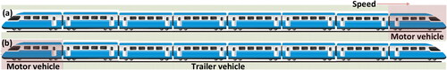
An Electric Multiple Unit (EMU) railway train is typically composed of multiple motor and trailer vehicles, operating in a fixed formation. These trains are known for their beneficial characteristics, including the absence of marshaling, relatively short train lengths, rapid acceleration, and high-frequency operation, leading to their extensive use globally (Xu et al. Citation2018). EMUs are categorized based on their maximum operating speeds into low-speed (less than 160 km/h), medium-speed (between 160 and 250 km/h), and high-speed (over 250 km/h) categories. Low-speed EMUs usually employ centralized power systems (Liu and Zhong Citation2020), whereas medium- and high-speed EMUs typically utilize distributed power systems (Shang et al. Citation2023; Li et al. Citation2022). Additionally, while low-speed EMUs are suitable for ballasted tracks, medium- and high-speed EMUs are better operated on ballastless tracks. By the end of 2022, the operational mileage of China’s high-speed railways, which predominantly use ballastless tracks, had reached 42,000 km, representing only 27% of the total railway operating mileage in the country. Medium- and high-speed EMUs are generally restricted to high-speed railway lines to maintain optimal ride quality, safety, and efficiency, posing challenges in enhancing transport efficiency on existing ballasted tracks. Consequently, to meet the increasing travel demands of the population, power centralized medium-speed EMUs have been designed and manufactured, following a comprehensive comparison of various indicators and technologies. This paper specifically focuses on the research of these medium-speed EMUs, hereinafter referred to as the EMUs.
The design of an EMU represents a significant challenge, necessitating considerable intellectual and financial resources, particularly for entirely new designs. Consequently, in the railway rolling stock industry, it is often preferable to base structural and machine designs on established, mature platforms (Dong et al. Citation2023). This approach is not unique to the railway sector but is also a common strategy in the aviation and automotive industries. However, while upgrades and new design features based on these platforms can introduce fresh challenges, they may also perpetuate issues inherent in the original design. Therefore, such redesigns present an optimal opportunity to resolve these existing problems. This paper specifically addresses one such design issue that emerged following an upgrade of EMUs.
The EMUs analyzed in this paper were upgraded from an established platform known for producing low-speed EMUs, featuring models like the plateau dual-source power centralized EMUs and the low-speed Fuxing Electric Multiple Unit (Liu and Zhong Citation2020). To increase their speed ranges from a maximum of 200 km/h to 250 km/h, the EMUs underwent upgrades in motor power and yaw damper positioning, enhancing the ride index. These two modifications notably reduced the likelihood of new issues arising with the EMUs. However, before these upgrades, the motor vehicles of low-speed EMUs were reported to have a lateral instability problem, mainly manifested as low-frequency lateral swaying of the carbody (Sun et al. Citation2019). Therefore, investigating and addressing the lateral instability of the EMUs during the design stage is crucial to significantly shorten the development cycle.
The core issue of low-frequency lateral swaying is hunting, typically occurring when the wheel tread has low conicity (Xia et al. Citation2019). This phenomenon has been observed in various rail vehicles worldwide, including locomotives, EMUs, and metros during testing and operation. For instance, Sun et al. (Citation2019) reported this in an electric locomotive, Park (Citation2021) in EMUs, and Shi et al. (Citation2020) in a metro. When low-frequency lateral swaying occurs in the carbody, especially when the main frequency of lateral swaying is below 2.0 Hz, the low-frequency lateral swaying of the carbody will seriously deteriorate the ride index of the vehicle. Jiang et al. (Citation2023, Citation2024) observed that low-frequency hunting could deteriorate the ride comfort of EMUs. Li et al. (Citation2022) found that the low frequency of lateral swaying poses a significant threat to the ride index and even the vehicle operational safety of the locomotive.
To address low-frequency lateral swaying, extensive research has led to two main strategies: optimizing vehicle suspension parameters and improving wheel-rail contact. Bustos et al. (Citation2022) identified the significant influence of vertical stiffness in the primary suspension and lateral damping in the secondary suspension through root loci analysis. Qu et al. (Citation2021) found that reducing wheelset equivalent conicity and primary suspension stiffness effectively mitigates train hunting instability. Similarly, Huang et al. (Citation2023) optimized yaw damper damping to eliminate low-frequency swaying in a locomotive. Kumar et al. (Citation2019) demonstrated the sensitivity of hunting instability to primary and secondary springs, secondary dampers, and wheel conicity using a 31-degree model. Wei et al. (Citation2017) suggested that decreasing wheel flange thickness or grinding rail corners, thereby lowering wheel-rail contact conicity, could improve lateral swaying. Kaiser et al. (Citation2018) observed that certain contact geometries lead to high hunting frequencies. Matsumoto et al. (Citation1999) found that optimizing the wheel tread profile and adjusting the longitudinal primary stiffness asymmetry could alleviate low-frequency lateral swaying. Lastly, Liu and Markine (Citation2020) emphasized that timely and correct rail maintenance can effectively reduce carbody hunting.
Although the aforementioned scholars have utilized diverse methodologies to tackle lateral swaying from various angles, their studies are primarily based on previously documented instances of carbody lateral swaying. When low-frequency lateral swaying occurs, remedial measures are implemented, but these are reactive solutions. They are often constrained by on-site conditions and tend to escalate the cost of vehicle development. Therefore, this paper aims to investigate the reproducibility of dynamic problems originating from the existing vehicle models of the platform in newly designed vehicles. This investigation focuses on the similarities in mechanics and emphasizes proactive solutions during the design stage.
The methodology comprises three primary steps. First, the dynamic model of the Base EMU system is validated using test data, successfully replicating the low-frequency lateral swaying observed in the Base EMUs. Second, by applying the principle of mechanical similarity, the validity of the dynamic model for the upgraded EMUs is indirectly verified, which also reveals the presence of low-frequency lateral swaying in these units. Finally, the study delves into identifying the underlying causes of low-frequency lateral swaying in EMUs and exploring reasonable adjustments in suspension parameters to mitigate this issue.
2. The design of the EMU systems and mechanics-based models
The Base EMU, characterized as a low-speed model, has seen widespread use across numerous existing railway lines. Its composition is succinct, featuring a single-end power configuration that includes one motor vehicle, seven trailer vehicles, and one control vehicle. The primary differences between the Base EMUs and the upgraded EMUs are found in the traction system and yaw dampers of the motor vehicle. Aside from these distinctions, the two types of EMUs share a high degree of similarity in other design aspects.
2.1. The design of the EMU systems
illustrates the schematic diagram of the bogie structure for the motor vehicle of Base EMUs. This vehicle employs a B0-B0 axle type, with a primary suspension comprising coil springs, axle box pull rods, and vertical dampers. The secondary suspension features coil springs combined with rubber damping, complemented by vertical and lateral dampers, as well as yaw dampers. The traction system uses a low traction beam for force transmission, while the primary braking system consists of wheel disk brakes. The bogie structure of the EMUs closely resembles that of the Base EMUs, with the notable difference being the angle of the yaw damper in horizontal plane (10.8° in Base EMUs versus 0° in EMUs). Apart from this variation, the mature technology of the Base EMUs is retained.
Figure 1. Bogie design: (a) motor vehicle (Base EMUs); (b) trailer vehicle.
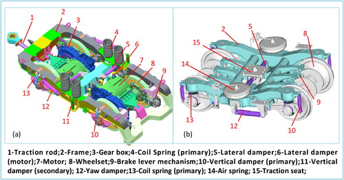
The trailer vehicles are the same for both Base EMUs and EMUs, are depicted in , showcasing the structure of the bogie model. The primary suspension system includes coil springs on the axle box and vertical dampers. The secondary suspension employs air springs, lateral dampers, and yaw damper dampers.
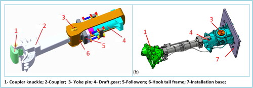
Regarding coupling systems, as demonstrated in , both Base EMUs and EMUs utilize a combination of the slack couplers (Wu et al. Citation2023; Eckert et al. Citation2023) and slackless coupler (Wu et al. Citation2023). The slack coupler, shown in , incorporates a polymer type buffer, featuring a 30 kJ capacity and a 63 mm stroke. Conversely, the slackless coupler, depicted in , uses a tube type buffer, also with a 30 kJ capacity, but with a 73 mm stroke.
Figure 2. Coupler design for: (a) slack coupler (motor vehicle); (b) slackless coupler (trailer vehicle).
2.2. Mechanics-based models
The mechanics-based models of Base EMUs and EMUs were constructed in the SIMPACK software, incorporating their structural and dynamic parameters, as well as the wheel-rail profile, as depicted in . lists the key parameters employed in the simulation. For the trailers’ vehicle, the dynamic model is formulated based on its structural features and dynamic parameters, alongside the wheel-rail profile. Similarly, the dynamic model of the coupler is developed using its structural and dynamic characteristics. The vertical and tangential forces of wheel-rail contact are calculated using Hertz’s theory and Kalker’s FASTSIM model. The behavior of the draft gear is mathematically modeled by EquationEqs. (1)(1)
(1) to Equation3)
(3)
(3) (Millan et al. (Citation2022). illustrates the buffer’s displacement and impedance force during the coupler’s cyclic excitation, demonstrating that these factors accurately capture the coupler’s intrinsic dynamics, thereby validating the coupler dynamics model.
(1)
(1)
(2)
(2)
(3)
(3)
Figure 3. The mechanics-based models: (a) vehicles; (b) equivalent conicity; (c) wheel-rail contact.
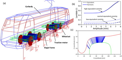
Figure 4. Displacement and impedance force of the buffer.
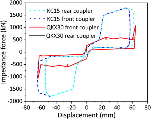
Table 1. Key simulation parameters (Base EMUs).
Where is the impedance force of the buffer at the moment t.
and
are the current step and the previous step traveling of the buffer at the moment t.
and
are the current step and the previous step deformation speed of the buffer at the moment t.
and
are the loading and unloading functions of the buffer at the moment t. and
is the transition stiffness.
The train dynamics models of Base EMUs and EMUs are differentiated into push and pull train models, depending on the positioning of the motor and trailer vehicles, as shown in . The wheel-rail contact condition, which can change depending on the line used or after a certain amount of mileage, significantly influences the dynamic performance of the vehicle (Escalona et al. Citation2019, Schupp Citation2003). This aspect is quantified using equivalent conicity. An equivalent conicity of 0.1 represents new wheels and rails, while 0.5 indicates severe wheel-rail wear, corresponding to high conicity. A value of 0.05 is indicative of low conicity, typically seen in trains operating on certain passenger lines, as shown in .
Figure 5. The train models: (a) Pull train model; (b) push train model.
3. Model validation and the design of lateral stability
This section discusses the measured dynamic response of the Base EMU on railways, focusing on track irregularities, ride index, and lateral swaying frequencies. It highlights the use of different types of track irregularities for simulation, revealing variations in ride index and vibration frequencies during train pulling and pushing. This section also examines bogie hunting frequencies and the impact of suspension parameters on the lateral swaying of the vehicle’s carbody and bogie, using mathematical models and empirical data.
3.1. Ride index
Track irregularity is a crucial excitation factor in the wheel-rail system, significantly impacting the dynamic response. The scatter diagram in presents the measured data of the ride index for Base EMUs operating on an actual railway line based on GB5599-2019. While these lines are managed to approximate the AAR 6 level (Iwnicki et al. Citation2019) of smoothness, actual track irregularities demonstrate random fluctuations. To validate the dynamics model and determine appropriate track irregularities for simulation, this study considers the AAR6 level, along with German low- and high-frequency spectra, establishing five types of track irregularities. These irregularities are characterized by their amplitude limit values and irregularity wavelength (A and Amax are the minimum and maximum amplitude, which set the track irregularities. y and z denote track irregularities in the lateral and vertical directions, respectively. Lave is the range of the mean value.). Key observations include: 1) The testing point is situated near the driver’s seat, at the front of the pull train and the rear of the push train; 2) At identical speeds, a large dispersion interval is noted in the scatter plot. Drivers may subjectively perceive severe lateral swaying of the carbody, causing a sudden rise in the ride index from the lower to the upper edge of the interval, despite the actual index remaining excellent. As shown in , the simulated results using the AAR6 level spectrum fall short of encompassing the actual measured values. However, when employing the 4th type of irregularity for simulation, the ride index more closely aligns with the test results. For speeds above 160 km/h, the predictions exceed the actual measurements when using the 5th type of irregularity. Therefore, the simulation incorporates both the 4th and 5th types of irregularities.
Figure 6. Ride index of Base EMUs wheel pulling trains.
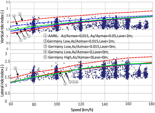
displays the scatter diagram of the ride index during train pushing operations, showing trends consistent with those observed during pulling operations. For speeds exceeding 160 km/h, results derived from the 4th type of track irregularity show satisfactory agreement with experimental data. Conversely, at speeds below 160 km/h, calculations using the 5th type of irregularity align well with the test data.
Figure 7. Ride index of Base EMUs wheel pushing trains.
3.2. Low-frequency lateral swaying
Previous studies (Sun et al Citation2019) have identified the occurrence of low-frequency lateral swaying during the operation of Base EMUs. This phenomenon tends to diminish over a certain mileage but becomes more pronounced when Base EMUs operate on ballastless tracks. illustrates the carbody’s vibration frequency during a line test, indicating that the primary vibration frequency is around 1.0 Hz. Dynamic simulation results, as shown in , corroborate this finding. When analyzing the established dynamic model and track irregularity, the primary frequency of lateral vibration is approximately 1 Hz at low and normal equivalent conicity. However, as the equivalent conicity increases to 0.5, the primary frequency approaches 2 Hz and the amplitude decreases notably. This suggests that the dynamic model for Base EMUs, as established in this study, is reasonable and capable of accurately predicting dynamic responses.
Figure 8. Vibration frequency of Base EMUs.
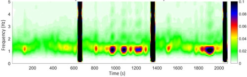
Figure 9. Frequency of carbody.
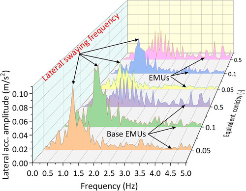
As substantiated in Section 2.1, the bogie structure of Base EMUs’ motor vehicle closely resembles that of the EMUs. Therefore, based on structural similarity theory (Zhang Citation1997), the validity of the Base EMUs’ dynamic model indirectly supports the reasonableness of the EMUs’ dynamic model. Despite a reduction in the lateral vibration amplitude of the carbody, the main frequency of this vibration persists, as depicted in . Consequently, it can be inferred that the low-frequency lateral swaying phenomenon observed in Base EMUs is also present in EMUs, albeit with different amplitudes. This indicates that the suspension parameters of EMUs do not entirely eliminate the carbody’s low-frequency lateral swaying.
The bogie hunting frequencies for both the Base EMUs and EMUs are analyzed and presented in . The frequencies range from 1.27 to 1.5 Hz for speeds between 120 km/h and 200 km/h. Given the near-identical nature of the bogie hunting frequency to the carbody vibration frequency and its relationship with equivalent conicity, wheel-rail contact emerges as a critical factor in lateral swaying.
Table 2. Bogie-related eigen frequencies (equivalent conicity of 0.1).
3.3. Theoretical analysis
Research conducted by Huang et al. (Citation2023) has highlighted that low-frequency lateral swaying is closely linked to the modal behavior of the vehicle, particularly concerning the lateral swaying and yaw movements of both the bogie and the carbody. To quantify these movements, Luo and Shi (Citation2018) have provided mathematical expressions, specifically EquationEqs. (4)(4)
(4) to Equation(5)
(5)
(5) , which describe the lateral swaying and yaw frequencies of a bogie, excluding the effects of damping:
(4)
(4)
(5)
(5)
and
are the longitudinal and lateral stiffness of primary suspension;
is the lateral stiffness of secondary suspension;
is half of the wheelbase;
and
are half of the lateral distance of the primary and secondary suspension;
and
are the mass and yaw inertia of the bogie.
The yaw and lateral swaying frequencies of carbody are shown in EquationEqs. (6)(6)
(6) to Equation7)
(7)
(7) (Luo and Shi (Citation2018):
(6)
(6)
(7)
(7)
and
are the longitudinal and vertical stiffness of secondary suspension;
is half of bogie base;
is the vertical distance between the mass center of carbody and the secondary suspension;
is the stiffness of the bogie anti-roll torsion bar;
and
are the mass, yaw inertia and rolling inertia of carbody. The positive and negative signs in EquationEq. (7)
(7)
(7) correspond to the upper and lower lateral swaying, respectively.
According to the dynamic parameters presented in , the lateral swaying and yaw frequencies of the bogie, as well as the yaw and lateral swaying frequencies of the carbody, are delineated in . An estimation of the yaw and lateral swaying frequency of the carbody is approximately 1 Hz, as inferred from the data.
Table 3. Vibration frequency.
4. Numerical results and discussion
Building on the previously validated dynamic model, this section conducts an in-depth analysis of the dynamic response, specifically focusing on the ride index and lateral swaying of EMUs at various stages of wheel wear.
4.1. Lateral ride index
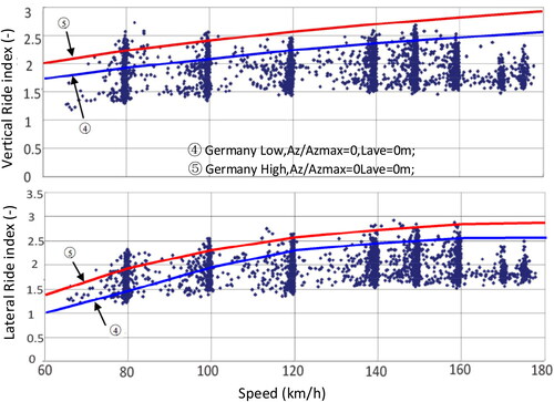
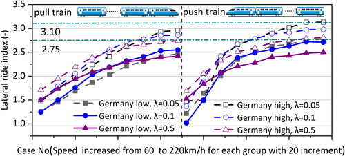
displays the lateral ride index of EMUs and its variation under different conditions. It shows that the lateral ride index gradually worsens as equivalent conicity increases, particularly when the train is pulled at speeds not exceeding 120 km/h. Additionally, when the train’s speed exceeds 180 km/h on tracks with Germany high track irregularity, there’s a noticeable decline in the lateral ride index as the equivalent conicity decreases. In contrast, when the train is pushed at speeds above 140 km/h, the lateral ride index progressively worsens with decreasing equivalent conicity. Across the speed range of 80 km/h to 220 km/h, the lateral ride index is consistently better when the train is pulled rather than pushed. This difference can be attributed to the deflection of the coupler during pushing operations, which amplifies the lateral vibration of the carbody and consequently degrades the lateral ride index.
Figure 10. Lateral ride index (EMUs).
presents a comparison of the ride indexes for EMUs and Base EMUs. It was observed that during pulling operations, the ride index of EMUs is superior to that of Base EMUs at speeds below 140 km/h. However, at speeds exceeding 160 km/h, an increase in equivalent conicity results in a higher ride index for Base EMUs compared to EMUs. Notably, the carbody’s ride index remains excellent across different equivalent conicities during pulling operations. In contrast, when pushing the train, the ride index of EMUs is generally higher than that of Base EMUs under normal and high conicity conditions. The exception to this trend occurs at low conicity, where, at speeds above 180 km/h, the ride index of Base EMUs falls below that of EMUs, contrary to the pattern observed under other conditions.
Figure 11. Lateral ride index (EMU and Base EMU).
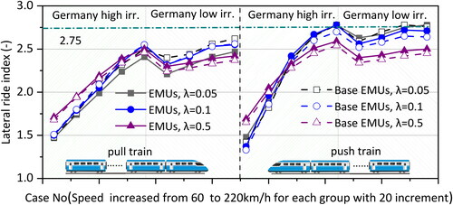
From this analysis, it can be inferred that the use of a yaw damper without an angle is more effective in improving the lateral ride index during pulling operations. Conversely, a yaw damper with an angle is more beneficial for enhancing the lateral ride index during pushing operations.
4.2. Dynamic response
During testing of the Base EMUs, it was noted that while the ride index remained excellent under both low and high conicity, significant lateral swaying of the carbody was observed under low conicity. In contrast, under high conicity, the ride index was still excellent, but with no prominent lateral swaying. This section aims to compare the lateral swaying characteristics of Base EMUs under both low and high conicity with those of EMUs under low conicity.
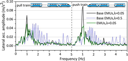
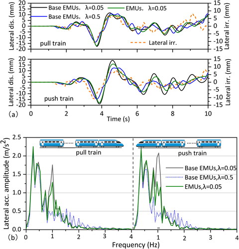
As shown in , the frequency spectrum of lateral vibration at a speed of 160 km/h (maxmium operation speed of base EMUs) on Germany’s low irregularity track reveals distinct patterns. Under high conicity, Base EMUs exhibit a rich vibration frequency with two notable areas of concentration in the low frequency range (below 5 Hz). Conversely, under low conicity, the primary frequency of lateral vibration in EMUs is approximately 1 Hz, albeit with a smaller amplitude than that of Base EMUs. This indicates that a yaw damper without an angle can effectively reduce lateral vibration. Additionally, the amplitude of lateral swaying in Base EMUs is larger in the pushing condition than in the pulling condition, suggesting that low-frequency lateral swaying is more significant during pushing. This observation aligns with the measured data from line tests, confirming the accuracy of the dynamic model in reflecting the EMUs’ dynamic response and the presence of low-frequency lateral swaying.
Figure 12. Lateral acceleration spectrum in Germany low irregularity.
At a speed of 160 km/h, the hunting frequency of the bogie is approximately 1.4 Hz, closely matching the carbody’s vibration frequency. This correlation suggests that the low-frequency lateral swaying of the carbody may be influenced by the hunting motion of the bogie, indicating that the bogie’s hunting frequency could be a direct cause of the low-frequency lateral swaying (Bustos et al. 2023).
depicts the lateral displacement and spectrum of the carbody when the train navigates the Germany low irregularity track at a velocity of 160 km/h. It is observed that, under high conicity conditions, the lateral displacement of Base EMUs primarily aligns with track changes. However, under low conicity, the carbody’s displacement oscillation is intensified by the excitation due to track directional irregularity, with a notably prominent displacement amplitude near 1 Hz. Comparatively, the displacement amplitude of Base EMUs under low conicity is significantly more pronounced than that of EMUs. This suggests that while the noticeable single-frequency lateral swaying of EMUs at low conicity can be considerably improved, it is not completely eliminated. Additionally, a main frequency of approximately 0.5 Hz is present in various wheel-rail contacts, closely corresponding to the yaw and lateral swaying frequencies of the carbody. When comparing the spectral plots of lateral acceleration and lateral displacement, it is evident that the spectrum of lateral displacement provides a more intuitive understanding than that of lateral acceleration at a frequency of 1 Hz.
Figure 13. Lateral displacement in Germany low irregularity: (a) Lateral displacement; (b) lateral displacement spectrum.
4.3. Influence of suspension on low-frequency lateral swaying
The analysis indicates that the ride index is at its poorest under conditions of low conicity and when pushing the train. To address this issue, this section focuses on optimizing the suspension parameters of EMUs, particularly under low conicity conditions during pushing operations. As noted in the literature (Matsumoto et al. Citation1999, Kumar et al. Citation2019), the damping of the yaw damper and the longitudinal primary stiffness significantly affect lateral low-frequency swaying. EquationEquation (5)(5)
(5) also suggests the impact of longitudinal primary stiffness on bogie hunting. Therefore, this section examines the influence of these two parameters on lateral low-frequency swaying.
The study utilizes the current yaw damper model to investigate the lateral displacement spectrum of the carbody under various conditions: traction, Germany low irregularity, and operating at 200 km/h. The investigation involves adjusting yaw damper damping and longitudinal primary stiffness. As shown in , lower yaw damper damping appears to suppress the pronounced low-frequency lateral swaying. However, when reducing yaw damper damping, it is crucial to recalibrate its dynamic performance for high conicity wheel-rail relationships.
Figure 14. Effect of yaw damper on the lateral displacement spectrum.
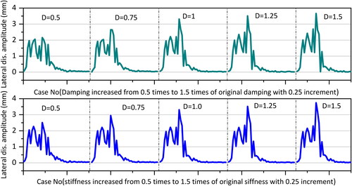
Additionally, a lower longitudinal primary stiffness is found to be effective in reducing prominent low-frequency swaying. As highlighted in the literature (Antali and StepanCitation2016), the hunting frequency of the wheelset, which is considered the primary suspension force, tends to decrease as the longitudinal suspension stiffness is reduced. Consequently, lowering the longitudinal positioning of the wheelset’s primary suspension can diminish the energy transfer from the wheelset to the carbody, thus mitigating the low-frequency lateral swaying of the carbody.
5. Conclusion
In this study, the mechanics-based model of the Base EMU was validated using data from a line test of Base EMUs. Following this, the study explored the optimal suspension parameter matching for bogies, focusing on the lateral swaying of railway EMUs, using the validated dynamics model. The dynamic simulations led to several key conclusions:
Inadequate wheel-rail guiding capacity under low conicity can led to the occurrence of low-frequency lateral swaying, reducing the wheelset’s ability to adapt to irregularities. Additionally, when the train is pushed, the coupler’s lateral force aggravates the wheel-rail guiding force under low conicity. This results in worsened ride quality and increased lateral swaying of the carbody compared to when the train is pulled.
Altering the yaw damper’s angle and damping properties can significantly reduce lateral swaying and improve the ride index. Adjusting the yaw damper’s angle, without major design modifications, can produce effects akin to condensing the arm of the yaw damper damping force. This reduces constraints on the carbody, enhancing stability.
Decreasing the stiffness of the axle box pull rod is effective in mitigating low-frequency lateral swaying. This approach is grounded in the principle of reducing the hunting frequency of the wheelset and enhancing its guiding capability.
Disclosure statement
No potential conflict of interest was reported by the author(s).
Additional information
Funding
References
- Antali, M., and G. Stepan. 2016. “On the Nonlinear Kinematic Oscillations of Railway Wheelsets.” Journal of Computational and Nonlinear Dynamics; 11 (5): 051020. https://doi.org/10.1115/1.4033034
- Bustos, A., M. Tomas-Rodriguez, H. Rubio, and C. Castejon. 2022. “On the Nonlinear Hunting Stability of a High-Speed Train Bogie.” Nonlinear Dynamics 111 (3): 2059–2078. https://doi.org/10.1007/s11071-022-07937-y
- Dong, H., F. Zhu, Y. Liu, D. Lv, X. Zhang, and J. Niu. 2023. “Improved Delayed Detached Eddy Simulation-Based Investigation of Aerodynamic Performance and Flow Field Characteristics of High-Speed Trains with Plate Brakes.” Mechanics Based Design of Structures and Machines: 1–17. https://doi.org/10.1080/15397734.2023.2232848
- Eckert, J. J., Í. P. Teodoro, L. H. Teixeira, T. S. Martins, P. R. Kurka, and A. A. Santos. 2023. “A Fast Simulation Approach to Assess Draft Gear Loads for Heavy Haul Trains during Braking.” Mechanics Based Design of Structures and Machines 51 (3): 1606–1625. https://doi.org/10.1080/15397734.2021.1-875233
- Escalona, J. L., J. F. Aceituno, P. Urda, and O. Balling. 2019. “Railway Multibody Simulation with the Knife-Edge-Equivalent Wheel–Rail Constraint Equations.” Multibody System Dynamics 48 (4): 373–402. https://doi.org/10.1007/s11044-019-09708-x
- Huang, C., H. Dai, and S. Qu. 2023. “Suppression of Carbody Hunting for a Locomotive Caused by Low Wheel–Rail Contact Conicity by Optimising Yaw Damper Location.” Vehicle System Dynamics: 1–23. https://doi.org/10.1080/00423114.2023.2280217
- Iwnicki, S. D., M. Spiryagin, C. Cole, and T. McSweeney. 2019. Handbook of Railway Vehicle Dynamics. Boca Raton, FL: CRC Press - Taylor & Francis Group. https://doi.org/10.1201/9780429469398
- Jiang, L., K. Peng, W. Zhou, and J. Yu. 2023. “Study on the Seismic Influence Coefficient of Track Irregularity on the Train Dynamic Effect of High-Speed Railway Bridge.” Mechanics Based Design of Structures and Machines 52 (6): 3339–3357. https://doi.org/10.1080/15397734.2023.2201358
- Jiang, C., H. Zhang, L. Ling, X. Ma, J. Gao, X. Ding, K. Wang, and W. Zhai. 2024. “The Effect of Yaw Damper Performance Degradation on Carbody Hunting of High-Speed Trains.” Vehicle System Dynamics: 1–24. https://doi.org/10.1080/00423114.2024.2317397
- Kaiser, I., G. Poll, G. Voss, and J. Vinolas. 2018. “The Impact of Structural Flexibilities of Wheelsets and Rails on the Hunting Behaviour of a Railway Vehicle.” Vehicle System Dynamics 57 (4): 564–594. https://doi.org/10.1080/00423114.2018.1484933
- Kumar, V., V. Rastogi, and P. Pathak. 2019. “Modelling and Evaluation of the Hunting Behaviour of a High-Speed Railway Vehicle on Curved Track.” Proceedings of the Institution of Mechanical Engineers, Part F: Journal of Rail and Rapid Transit 233 (2): 220–236. https://doi.org/10.1177/095440971878-9531
- Liu, L., and Z. Zhong. 2020. Introduction to high-speed railway. Chengdu, China: Southwest Jiaotong University Press Chengdu. 145–146. https://doi.org/10.1007/978-981-99-6423-9_4
- Liu, X., and V. L. Markine. 2020. “Train Hunting Related Fast Degradation of a Railway Crossing—Condition Monitoring and Numerical Verification.” Sensors 20 (8): 2278. https://doi.org/10.3390/s20082278
- Li, G., Y. Zhou, Y. Yao, X. Hu, and L. Wei. 2022. “Application of Yaw Dampers with Frequency-Selective Damping to Improve the Locomotive Adaptability to Low/High Conicity Stability.” Proceedings of the Institution of Mechanical Engineers, Part F: Journal of Rail and Rapid Transit 237 (6): 784–795. https://doi.org/10.1177/09544097221141517
- Luo, R., and H. Shi. 2018. Dynamics of Railway Vehicle Systems and Aplication, 2018. Chengdu: Southwest Jiaotong University Press. 176–191.
- Matsumoto, A, Y. Sato, H. Ohno, Y. Suda, R-I. Nishimura, M. Tanimoto, Y. Oka, and E. Miyauchi. 1999. “Compatibility of Curving Performance and Hunting Stability of Railway Bogie.” Vehicle System Dynamics 33 (sup1): 740–748. https://doi.org/10.1080/00423114.1999.12063126
- Millan, P., J. Pagaimo, H. Magalhães, and J. Ambrósio. 2022. “Clearance Joints and Friction Models for the Modelling of Friction Damped Railway Freight Vehicles.” Multibody System Dynamics 58 (1): 21–45. https://doi.org/10.1007/s11044-022-09857-6
- Park, J. 2021. “Investigation of Low Damped Carbody Oscillation for Korean High-Speed EMU Experimental Train.” Proceedings of the Institution of Mechanical Engineers, Part F: Journal of Rail and Rapid Transit 236 (1): 109–121. https://doi.org/10.1177/09544097211008289
- Qu, S., J. Wang, D. Zhang, D. Li, and L. Wei. 2021. “Failure Analysis on Bogie Frame with Fatigue Cracks Caused by Hunting Instability.” Engineering Failure Analysis 128: 105584. https://doi.org/10.1016/j.engfailanal.2021.105584
- Schupp, G. 2003. “Simulation of Railway Vehicles: Necessities and Applications.” Mechanics Based Design of Structures and Machines 31 (3): 297–314. https://doi.org/10.1081/SME-120022852
- Shang, W., G. Gao, X. Miao, J. Zhang, and J. Wang. 2023. “Impact of Bogie Fairing Configuration on the Aerodynamic Performance of High-Speed Train under Crosswind.” Mechanics Based Design of Structures and Machines: 1–24. https://doi.org/10.1080/15397734.2023.2272686
- Shi, Y., H. Dai, Q. Wang, L. Wei, and H. Shi. 2020. “Research on Low-Frequency Swaying Mechanism of Metro Vehicles Based on Wheel-Rail Relationship.” Shock and Vibration 2020: 1–15. https://doi.org/10.1155/2020/8878020
- Sun, J., M. Chi, X. Jin, S. Liang, J. Wang, and W. Li. 2019. “Experimental and Numerical Study on Carbody Hunting of Electric Locomotive Induced by Low Wheel–Rail Contact Conicity.” Vehicle System Dynamics 59 (2): 203–223. https://doi.org/10.1080/00423114.2019.1674344
- Wei, L., J. Zeng, M. Chi, and J. Wang. 2017. “Carbody Elastic Vibrations of High-Speed Vehicles Caused by Bogie Hunting Instability.” Vehicle System Dynamics 55 (9): 1321–1342. https://doi.org/10.1080/00423114.2017.1310386
- Wu, Q., C. Cole, M. Spiryagin, and P. Liu. 2023. “Parallel co-Simulation of Heavy-Haul Train Braking Dynamics with Strong Nonlinearities.” Mechanics Based Design of Structures and Machines 52 (5), 2623–2638. https://doi.org/10.1080/15397734.2023.2187414
- Wu, Q., X. Ge, S. Zhu, C. Cole, and M. Spiryagin. 2023. “Physical Coupling and Decoupling of Railway Trains at Cruising Speeds: Train Control and Dynamics.” International Journal of Rail Transportation 12 (2): 217–232. https://doi.org/10.1080/23248378.2023.2169963
- Xia, Z., J. Zhou, J. Liang, S. Ding, D. Gong, W. Sun, and Y. Sun. 2019. “Online Detection and Control of Car Body Low-Frequency Swaying in Railway Vehicles.” Vehicle System Dynamics 59 (1): 70–100. https://doi.org/10.1080/00423114.2019.1664751
- Xu, K., Z. Feng, H. Wu, F. Li, and C. Shao. 2018. “Investigating the Influence of Rail Grinding on Stability, Vibration, and Ride Comfort of High-Speed Emus Using Multi-Body Dynamics Modelling.” Vehicle System Dynamics 57 (11): 1621–1642. https://doi.org/10.1080/00423114.2018.1539234
- Zhang, Z. 1997. “Study on Similitude Laws for Shaking Table Tests.” Earthquake Engineering and Engineering vibration 12 (2): 52–58.