
 ?Mathematical formulae have been encoded as MathML and are displayed in this HTML version using MathJax in order to improve their display. Uncheck the box to turn MathJax off. This feature requires Javascript. Click on a formula to zoom.
Abstract
Head-mounted displays (HMDs) for augmented reality (AR) and virtual reality (VR) are expected to have a wide field of view, high resolution, no artifacts, vergence accommodation conflict (VAC) management, and compactness. To meet these requirements, liquid crystal technologies have attracted considerable attention as displays and optical elements. In this paper, liquid crystal technologies for AR/VR HMDs are reviewed. Short-range lurch control in-plane switching (SLC-IPS) LCDs with fast response properties decrease the motion blur artifact. A liquid crystal lens with varifocal properties can solve the VAC problem. Pancharatnam–Berry phase optical elements contribute to high resolution, the management of VAC, and compactness.
1. Introduction
Head-mounted displays (HMDs) or near-eye displays for augmented reality (AR) and virtual reality (VR) play an important role in the metaverse. In AR, digital content and information are superimposed on a real-world scene. HMDs for AR should achieve a see-through representation. In VR, digital images cover the entire field of view (FOV), and 360-degree viewing of an image is made possible by head tracking. HMDs for VR should replicate the real world.
In VR, a display should show a motion picture while the head is moving, even if a still image is being viewed. Therefore, motion picture blur artifacts are important. HMDs can generate a 3D representation by displaying parallax images for each eye. However, such a stereoscopic display has a vergence-accommodation conflict (VAC) problem. VAC has been reported to cause visual discomfort and fatigue [Citation1,Citation2].
HMDs for AR require very small displays. Therefore, liquid crystal on silicon (LCOS) and micro-OLED (organic light-emitting diode) are generally used. In HMDs for VR, in-plane switching liquid crystal displays (IPS-LCDs) [Citation3] or OLED displays with high image quality are used. In terms of pixel densities, LCDs are superior to OLEDs because the red, green, and blue (RGB) sub-pixels in LCDs are divided by precisely patterned color filters using photolithography, whereas they are generally fabricated by masked vapor deposition, which is less precise, in OLEDs. Recently, liquid crystal technologies for AR/VR have attracted considerable attention not only as displays but also as optical elements.
In this paper, several challenges in AR/VR HMDs are described. Then, the liquid crystal technologies that solve these challenges, i.e., fast response LCDs, liquid crystal lenses (LC lenses), and Pancharatnam–Berry phase optical elements (PBOEs), are reviewed.
2. Challenges in AR/VR HMDs
AR/VR HMDs are expected to have a wide FOV and a high resolution to replicate the real world. They should also have no artifacts, manage VAC for comfortable use, and be compact for all day use. For AR display, the see-through function is also required. In the following, motion blur artifacts, resolutions, and VACs are described in detail.
2.1. Motion blur artifact
In VR displays, motion picture blur artifacts are more significant than those in flat panel displays because a display shows motion pictures while the head is moving, even if a still image is being viewed. The impact of motion blur on VR has been discussed [Citation4,Citation5]. In hold-type displays, such as conventional LCDs and OLED displays, motion blur is a problem.
Consider that a person watches an image that is moving with a constant velocity on a display. In the case of a hold-type display, the displayed image is periodically shifted once in a frame period and is sustained during a frame period. However, the eyes continuously follow the image with a constant velocity. This mismatch causes motion picture blur [Citation6].
On the other hand, an impulse-type display, such as CRT (cathode ray tube) and film, does not have this problem because the shifted image is displayed for a moment once in a frame. This is equivalent to a quick flashing image that is continuously moving at a constant velocity and is seen without blur by the eyes when they are following at the same velocity.
To improve motion picture quality, an impulse-type LCD has been proposed [Citation6]. It is commonly used as a VR display. The backlight emits for a moment once in a frame, so the LCD functions as an impulse-type display. In impulse-type LCDs, the LC should respond within a time span that is much shorter than the frame period. Therefore, it requires a very-fast-response LCD mode.
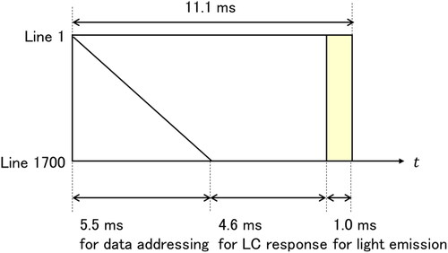
For example, a typical timing chart of an LCD for VR with a 90 Hz frame frequency and 1700 × 1700 pixels (1700 lines) is shown in [Citation4]. The horizontal and vertical axes denote the time and panel position, respectively. The frame period is 11.1 (=1/90) ms. The voltage that corresponds to the display data is sequentially applied to the pixels line by line. It takes 5.5 ms to address 1700 lines. After the LC responds, the backlight emits for 1 ms. Therefore, the LC should respond within 4.6 ms, as shown in . In the case of conventional LCDs, it is sufficient to respond within one frame period, 11.1 ms in this case. However, HMDs for VR require that the LC responds approximately twice as fast as in conventional LCDs.
Figure 1. Typical timing chart of the LCD for VR with 1700 lines driven at 90 Hz.
2.2. Resolution
In VR, a high-resolution display is required to replicate the real world. shows angular pixel density as a function of FOV, as given by [Citation5]
(1)
(1)
where
is angular pixel density in pixels per degree (ppd),
is resolution, and
is FOV. The acuity of a normal person with 20/20 vision is 1 arcmin, namely 60 ppd. In the case of an FOV of 100 degrees, 6000 (= 60 ppd
100 degree) pixels are necessary.
Figure 2. FOV vs. ppd.
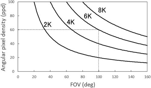
Typically, the width of an LCD is approximately 2 inches. Therefore, a high pixel density of 3000 pixels per inch (ppi) is needed. Achieving a high pixel density of 3000 ppi is challenging, although a VR HMD with an LCD of over 1000 ppi has recently been commercialized.
2.3. VAC
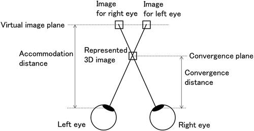
The VAC should be managed for a comfortable AR/VR experience. explains the conflict in visual representation between accommodation and convergence [Citation7]. Different images with parallax are displayed on the virtual image plane according to HMD optics. A 3D image is perceived at the convergence plane due to the parallax. The accommodation distance is defined as the distance between the virtual image plane and the eyes, whereas the convergence distance is defined as the distance between the convergence plane and the eyes. In a real scene, both the accommodation distance and the convergence distance are matched. However, in conventional HMDs, these distances are not matched. VAC has been reported to cause visual discomfort and fatigue [Citation1,Citation2].
Figure 3. Conflict in visual representation between accommodation and convergence.
3. Fast-response LCD mode
To reduce motion blur artifacts, a fast-response LCD mode is needed. In the HMDs for VR, IPS-LCDs with high image quality are used. According to the one-dimensional equation derived from the continuum theory [Citation8–11], the response properties of IPS-LCDs are described by the following equation [Citation12]:
(2)
(2)
where
and
are the time constants of decay and rise, respectively, with rotational viscosity
twist elastic constant
and thickness of the LC layer
is the threshold electric field given by
(3)
(3)
where
is the dielectric anisotropy of the LC and
is the dielectric constant of free space.
The response time decreases with a decrease in LC cell thickness. However, the retardation decreases with a decrease in the thickness and the transmittance of the LCD decreases. Furthermore, it is difficult to fabricate LCDs with a thin LC layer in mass production.
To improve the response properties of IPS-LCDs, several technologies have been proposed [Citation13–15]. Matsushima et al. proposed short-range lurch control in-plane switching (SLC-IPS) LCDs using the two-dimensional confinement of LCs [Citation13].
shows cross-sectional and top views of SLC-IPS LCDs and conventional IPS-LCDs. Both SLC and conventional IPS are driven by a lateral fringe electric field at the edges of the upper electrodes. The lateral fringe electric field is induced by the applied voltage between the upper electrodes and the lower electrode.
Figure 4. Cross-sectional and top views of SLC-IPS LCD and conventional IPS-LCD. Red dotted lines denote the imaginary boundary.

In the conventional IPS-LCD, the directors of the LC initially align in a slightly slanted direction from the upper electrode, so that all the directors rotate in the same direction when the voltage is applied, as schematically shown in .
In contrast, the directors in the SLC-IPS LCDs initially align parallel to the upper electrode, so that they rotate in the opposite direction, and the directors at the center of the upper electrodes and at the center of their gaps do not rotate, as is schematically shown in . In this way, the regions at the center of the upper electrodes and at the center of their gaps behave as an imaginary fixed boundary during the response, and they accelerate the response.
According to the two-dimensional equation derived from the continuum theory, where is defined as the distance between the imaginary boundaries or half of the upper electrode pitch, the response properties of SLC-IPS LCDs are described by the following equation [Citation4]:
(4)
(4)
where
and
are the time constants of decay and rise, respectively. Here, the splay and bend elastic constants,
and
are assumed to be the same
is the threshold electric field given by
(5)
(5)
The response time decreases with a decrease in the LC cell thickness and in the distance
Therefore, the response time can be reduced by decreasing the upper electrode pitch while maintaining the LC cell thickness.
Generally, and
are approximately twice the value of
Assuming that distance
is equal to the LC cell thickness
in EquationEq. (4)
(4)
(4) is expressed as
(6)
(6)
SLC-IPS is expected to be three times faster than conventional IPS.
shows the optical response properties measured for SLC-IPS and conventional IPS fabricated using the same LC material under the conditions of a LC cell thickness of 2.5 µm and a distance
of 2.5 µm. The optical rise time (10% to 90%) of the SLC-IPS is 2.7 ms, whereas that of the conventional IPS is 7.1 ms. The optical decay time (90% to 10%) of SLC-IPS is 1.8 ms, whereas that of the conventional IPS is 5.9 ms. The response time of the SLC-IPS is approximately one-third that of the conventional IPS, as was predicted by EquationEq. (6)
(6)
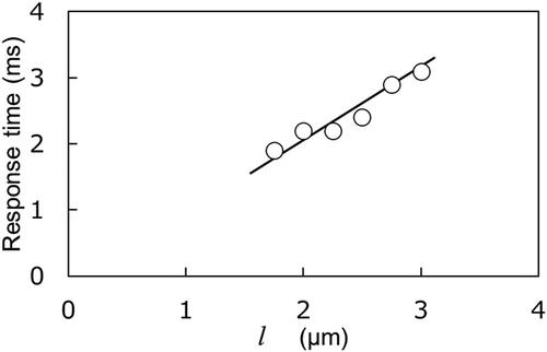
(6) . shows the measured optical decay response time (90% to 10%) of an SLC-IPS as a function of distance
The results confirm that the response time can be reduced by the distance
Figure 5. Optical response properties of SLC-IPS and conventional IPS.
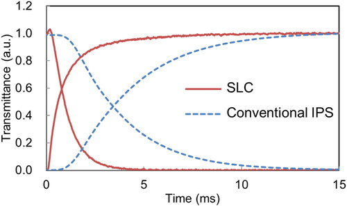
Figure 6. Optical decay response time (90% to 10%) of SLC-IPS as a function of distance
Matsushima et al. developed an SLC-IPS LCD for VR HMDs [Citation4]. The gray-to-gray (GTG) response time of the LCD is shown in . The optical rise time (10% to 90%) and the optical decay time (90% to 10%) of the SLC-IPS LCD are 1.9 and 2.3 ms, respectively. The slowest GTG response time is 4.5 ms, which meets the requirement for VR HMDs described in Section 2.1. The specifications of this LCD are summarized in . A motion-blur-free LCD with a 90 Hz frame frequency and 1700 lines was developed.
Figure 7. GTG response times of the developed LCD using SLC-IPS.
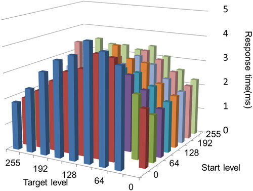
Table 1. Specifications for the developed LCD using SLC-IPS.
4. Liquid crystal lens
Several technologies are used to solve the VAC problem, such as the light field display with microlens arrays [Citation16], the volumetric display with a stack of LC scattering shutters [Citation17], the digital holographic display [Citation18], the Maxwellian view with direct projection on the human retina [Citation19], and the varifocal LC lens [Citation20]. The combinations of various optical designs with eye tracking are expected to alleviate the VAC [Citation21]. The varifocal LC lens coupled with a vergence eye-tracking system has the great potential for solving VAC. The eye tracking system can determine the convergence distance and the LC lens is adjusted to accommodate the convergence plane.
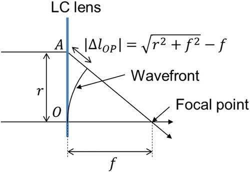
LC lenses have been developed since they were invented in 1979 [Citation22]. shows the optics of the LC lens. A wavefront is a spherical surface centered on the focal point when the rays converge at the focal point. Considering a spherical surface having a radius the phases on that spherical surface are identical. Therefore, the phase at A on the LC lens is delayed relative to the phase at O by
with the wavelength
and the optical path difference (OPD)
which is given by
(7)
(7)
Figure 8. Optics of the liquid crystal lens.
as shown in . When the focal length is much longer than the radius (), i.e., for a low-power lens, EquationEq. (7)
(7)
(7) is approximated by EquationEq. (8)
(8)
(8) , which includes up to the second-order term of the Taylor expansion [Citation23]:
(8)
(8)
where
is diopter defined by
in m units.
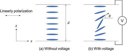
The phase generated when the ray passes through the LC depends on the director configurations of the LC. shows the director configurations of the LC lens. The director configuration of the LC layer is homogeneously aligned parallel to the x-axis when no voltage is applied. When a voltage is applied, the directors align according to the voltage, as shown in . The effective refractive index at with
for the linear polarization along the x-axis is given by [Citation23]:
(9)
(9)
where
and
are the ordinary and extraordinary refractive indices,
is the angle between the director and the LC layer plane, which depends on
and
The optical path length generated at
when the ray passes through the LC layer along the z-axis is expressed as follows:
(10)
(10)
where
is the thickness of the LC layer. The OPD is defined by
(11)
(11)
Figure 9. Director configuration of the LC lens.
If EquationEq. (11)(11)
(11) is equal to EquationEq. (8)
(8)
(8) , the LC layer functions as a lens with focal length
or the diopter
As the angle
is larger with an applied voltage than without a voltage, and
the value of the optical path length
is smaller with an applied voltage than without a voltage.
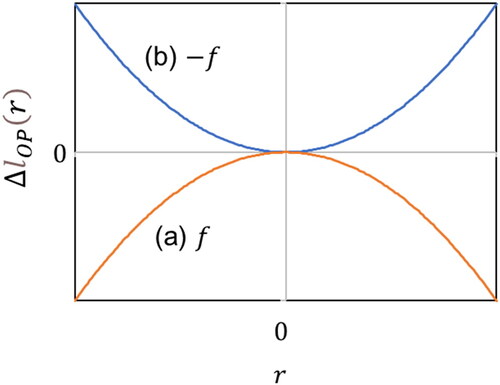
shows the OPD profiles of the LC layer. When no voltage is applied at the center () and a high voltage is applied at the periphery, the profile shown in is generated. This profile serves as a converging lens with a focal length of
Conversely, when a high voltage is applied at the center, profile (b) is generated and the LC layer functions as a diverging lens with a focal length of
as derived from EquationEq. (8)
(8)
(8) . The OPD profile varies continuously as
is continuously adjusted between
and
by changing the applied voltage. Therefore, the focal length of the LC lens can continuously vary between
and
i.e., it achieves a
continuous diopter swing.
Figure 10. OPD profiles of the LC lens: (a) focal length of with high applied voltage at the periphery, (b) focal length of
with high applied voltage at the center.
To satisfy EquationEq. (8)(8)
(8) , the OPD profile across the diameter of the lens is controlled by applying an electric field to the concentric ring electrode structure, as shown in [Citation23]. The LC lens comprises an LC layer between two transparent substrates. A common transparent electrode is fabricated on one substrate. Many discrete ring electrodes with inter-ring resistors are fabricated on the other substrate. The gap between the ring electrodes should be small relative to the thickness of the LC layer to align the LC director even in the gap due to the elasticity.
Figure 11. Concentric ring electrode structure.
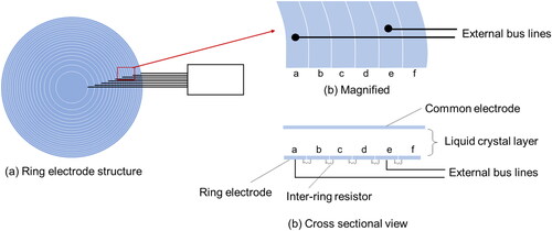
To realize the desired OPD profile, n of the discrete ring electrodes are individually connected to external bus lines. For example, ring electrodes “a” and “e” are addressed with external bus lines in . The lens has (n-1) regions of linear voltage drop because of the inter-ring resistors between any two adjacent electrodes. The LC director aligns depending on the applied voltage between the common and ring electrodes. The OPD profile given by EquationEq. (8)(8)
(8) can be achieved by designing the structure of the ring electrodes and applying the proper voltages to the bus lines.
The response time of the LC lens that is used for VR is estimated as follows. It has been reported that VAC can be solved completely with a 2 diopters (D) swing lens and solved minimally with a 1 D swing lens, assuming the objective distance between 0.5 m and infinity and an allowable discrepancy of 1/2 D [Citation20]. To obtain an optimal FOV in VR, the LC lens should be large. Typically, the distance between the eyes is approximately 65 mm. Therefore, the radius of the LC lens is limited to less than 32.5 (= 65/2) mm.
Considering an LC lens with a 25 mm radius and 1 D swing ( D), EquationEq. (8)
(8)
(8) gives an OPD of 156 µm. Considering EquationEqs. (9)
(9)
(9) and Equation(10)
(10)
(10) , the maximum OPD for an LC layer with
(
) and thickness
is equal to
Using
= 0.27 (which is a relatively high value for LC materials) and an OPD of 156 µm gives a thickness
= 578 µm, which is approximately 100 times thicker than that used in conventional LCDs. (The thickness of conventional LCDs is several microns.) The response time of the LC is proportional to the square of the thickness of the LC layer. Therefore, the response time is 1002 times longer than that of conventional LCDs.
Using a stack of lenses is effective for improving the response properties of the LC lens. The diopter of the stack of LC lenses is the sum of the diopters of each LC lens. By stacking LC lenses, the thickness of each LC lens can be reduced. However, using many LC lenses increases the thickness of HMDs.
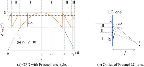
Fresnel facets are also effective for improving the response properties of the LC lens [Citation20]. The Fresnel facets are similar to the Fresnel lens, which reduces the thickness of an optical lens. explains the principle of the Fresnel LC lens with three facets. The OPD with the Fresnel lens style shown in has the same lens properties as that shown in . The optics are explained in . If the change in OPD at the facet is equal to an integer multiple of the wavelength () as shown in , the LC layer functions as the LC lens in . For example, to obtain the OPD profile shown in , the same voltages are applied to the ring electrodes at
and
Figure 12. Fresnel LC lens.
Bhowmick et al. proposed an LC lens with a 5 cm diameter and an 0.8 D optical swing for VR HMDs using a stack of lenses and Fresnel facets [Citation24]. Two LC lenses were stacked. Each lens was capable of continuous change in the diopter from −0.20 D to +0.20 D, i.e., a 0.40 D diopter swing. An LC material with = 0.27 was used. The thickness was reduced to approximately 12 µm with 28 Fresnel facets on the LC lens, which drastically reduced the switching time of the LC lens.
The image quality of the fabricated LC lens was tested using a negative USAF 1951 test target with fluorescent light illumination on the back. A linear polarizer was placed in front of the LC lens so that the linear polarization was parallel to the homogeneous LC director. Pictures were taken using a camera with the LC lens on the camera lens. An aperture stop having a diameter of 5 mm, which was chosen considering the average diameter of the human pupil, was attached to the LC lens surface. The position of the aperture stop was shifted from the center of the lens to the edge in 5 mm increments. MTF (Modulation Transfer Function) was measured from the pictures taken of the USAF 1951 test target corresponding to a spatial frequency of 10 cyc/deg (equivalent to 20 ppd).
The MTF value was 0.73 when no voltage was applied (lens off). When a voltage was applied, the MTF values were 0.70, 0.43, 0.56, 0.36, and 0.23 with the aperture stop at 0, 5, 10, 15, and 20 mm from the center. It has been reported that human eye MTF drops to 0.40 at 10 cyc/deg [Citation25]. A large-diameter LC lens with good MTF values was developed, although a drop in the MTF value was observed in the outer area of the lens. However, as it is expected that the users will move their head to generally maintain a gaze angle of less than approximately 25 degrees, the degradation in the MTF at larger angles may not be problematic [Citation24].
5. PBOEs
Recently, several LC technologies with PBOEs have been proposed to solve the challenges for AR/VR HMDs. In PBOEs, a phase is induced by the geometric configuration. The Pancharatnam–Berry phase, or geometric phase results from a change in polarization. LCs are used for PBOEs because the geometric phase can be easily obtained using photo-alignment technology [Citation26].
In 1956, Pancharatnam pointed out that if a polarization is converted to a common polarization state along two different paths on a Poincaré Sphere, a relative phase emerges between the two [Citation27]. In 1984, Berry more generally pointed out that during the diabatic cyclic evolution of a quantum system, a phase is added to the wave function, and this phase depends on the geometric properties of the path taken in the parameter space [Citation28]. It turns out that the Pancharatnam phase can be interpreted as the Berry phase.
5.1. Pancharatnam–Berry phase lens and deflector
The Pancharatnam–Berry phase lens (PBL) and Pancharatnam–Berry phase deflector (PBD) are described in this section. The principle of PBOEs can be described by Jones matrices, assuming an input circular polarization as
(12)
(12)
where
and
correspond to left- and right-handed circular polarization (LCP and RCP), respectively [Citation29]. When the input light passes through a half-wave plate with its slow axis defined by the angle
the output light is given by
(13)
(13)
where
and
with phase retardation
are the Jones matrices of the rotation and phase retardation, respectively. EquationEquation (13)
(13)
(13) indicates that when circular polarization passes through the half-wave plate, a phase difference of
occurs according to the angle
that defines the slow axis of the half-wave plate, and the handedness of the circular polarization becomes reversed.
Circular polarization with opposite handedness induces a phase with the same absolute value but the opposite sign. When a circular polarization is converted to a common opposite circular polarization by a half-wave plate with a different slow axis, a relative phase emerges, as Pancharatnam pointed out.
The optics of the PBLs are the same as those of the LC lens shown in . If the phase difference satisfies EquationEq. (14)
(14)
(14) regardless of the distance
the LC layer functions as a lens with a focal length
[Citation29].
(14)
(14)
where
is the OPD given by EquationEq. (8)
(8)
(8) . EquationEquation (14)
(14)
(14) indicates that the phase on the output plane of the LC lens at
is delayed relative to that at
which is at the center. Substituting the phase difference that occurs in PBL, which is given by
into EquationEq. (14)
(14)
(14) gives
(15)
(15)
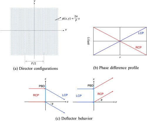
EquationEquation (15)(15)
(15) indicates that the LC aligns in a plane with its director rotating continuously along a radial axis as a quadratic function of
with a second-order coefficient inversely proportional to the wavelength and focal length, as shown in [Citation29]. A PBL with a focal length of
can be realized by designing LC director configurations that satisfy EquationEq. (15)
(15)
(15) with phase retardation
Figure 13. Pancharatnam–Berry lens (PBL).
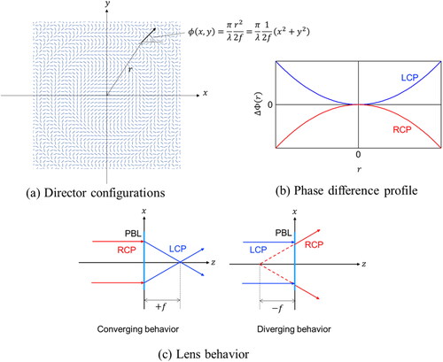
In a PBL, the opposite phase profile is induced for RCP and LCP input, as shown in . Considering EquationEq. (14)(14)
(14) , the opposite phase profile means the focal length has the opposite sign. The PBL functions as a converging lens for RCP and as a diverging lens for LCP, as shown in . Although a PBL has a strong chromatic effect, i.e., the focal length is inversely proportional to the wavelength, as shown in EquationEq. (15)
(15)
(15) , it has been reported that acceptable performance can be achieved for applications where the lens has low power and small aperture [Citation30].
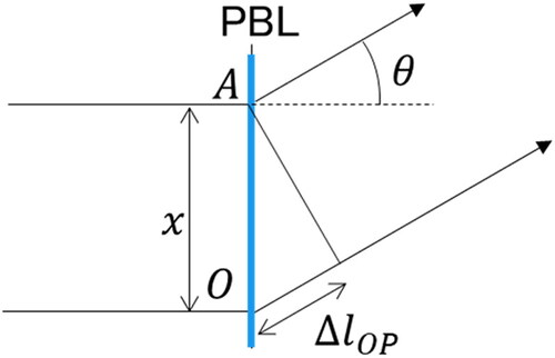
shows the optics of the PBD [Citation5]. When the rays deflect at an angle the phase at A on the LC lens is advanced to the phase at O by
with the wavelength
and the OPD
which is given by
(16)
(16)
as shown in . If the phase difference
satisfies EquationEq. (17)
(17)
(17) whatever the distance
the LC layer functions as a deflector with a deflection angle of
(17)
(17)
Figure 14. Optics of the Pancharatnam–Berry phase deflector (PBD).
Substituting the phase difference that occurs in PBD given by into EquationEq. (17)
(17)
(17) gives
(18)
(18)
EquationEquation (18)(18)
(18) indicates that the LC aligns in a plane with its director continuously rotating along the x-axis as a linear function of
as shown in [Citation5]. A PBD with a deflection angle of
can be realized by designing LC director configurations that satisfy EquationEq. (18)
(18)
(18) with phase retardation
Using the pitch
of the rotation of the director configuration,
is defined by
(19)
(19)
Figure 15. Pancharatnam–Berry deflector (PBD).
From EquationEqs. (18)(18)
(18) and Equation(19)
(19)
(19) , the deflection angle
is derived as follows:
(20)
(20)
In the PBD, the opposite phase profile is induced for RCP and LCP input in a way similar to the PBL, as shown in . Considering EquationEq. (17)(17)
(17) , the opposite phase profile means that the deflection occurs in the opposite direction. The PBD functions as a deflector for RCP and as a deflector in the opposite direction for LCP, as shown in . The PBD has a strong chromatic effect as well as the PBL, i.e., the deflection angle depends on the wavelength as shown in EquationEq. (20)
(20)
(20) .
Two methods for controlling PBOEs have been proposed: active driving and passive driving [Citation31]. shows active driving and passive driving for the PBL, respectively. Although PBL is given as an example, active driving and passive driving are also possible for PBD.
Figure 16. Active driving and passive driving of PBL.
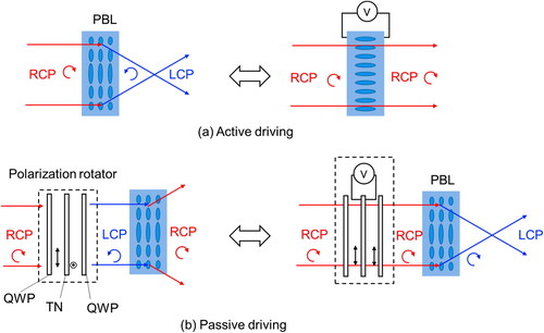
In active driving, a voltage is applied to the LC layer. With no voltage, the LC layer functions as a PBL. On the other hand, with an applied voltage, the LC directors uniformly align in the normal direction to the PBL plane that generates no phase difference. Therefore, the PBL functions as a transparent window. The switching speed of the active driving is fast because the phase retardation of is achieved using a thin LC layer. For example, considering the wavelength of 550 nm and a
of 0.1, the condition generating the phase retardation of
i.e.,
gives an LC layer thickness
equal to 2.75 µm, which is thinner than that used in LCDs.
In passive driving, a polarization rotator is added to the PBL. The polarization rotator switches the input polarization to the PBL between RCP and LCP. For example, the polarization rotator consists of a twisted nematic (TN) LC layer sandwiched between quarter-wave plates (QWPs), as shown in . The input RCP is converted to a linear polarization by the first QWP. Then, it is converted to an orthogonal linear polarization by the TN LC layer when no voltage is applied. The orthogonal linear polarization is converted to LCP by the second QWP. The PBL functions as a diverging lens for LCP.
On the other hand, when sufficient voltage is applied to the TN LC layer, it maintains the input linear polarization. The linear polarization is converted to RCP again by the second QWP. The PBL functions as a converging lens for the RCP. The passive driving for the PBL switches between converging and diverging lenses. The switching speed of the TN LC layer is fast enough that the passive driving also switches quickly.
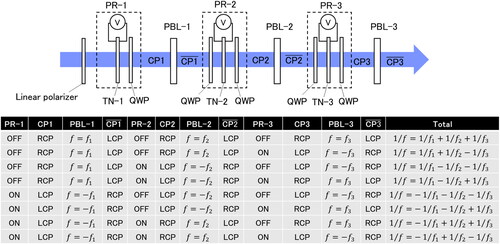
To vary the focal length, a stack of PBLs is needed because the active and passive driving of PBLs switch between only two states. Stacking N pieces of PBLs enables the focal length to have 2N switchable states, i.e., a 2N multifocal length. and show the stacking of the active PBLs and passive PBLs, respectively. Three stacked PBLs are illustrated as examples.
Figure 17. Stack of active PBLs.
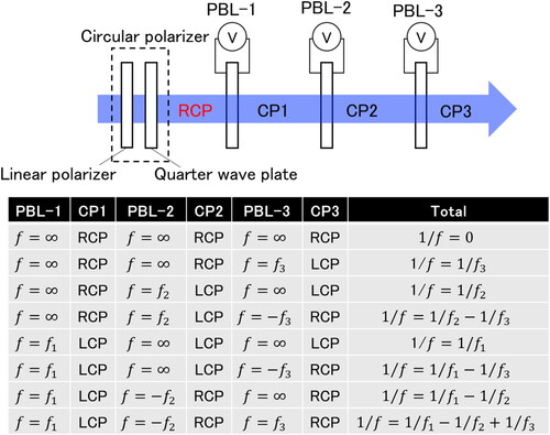
Figure 18. Stack of passive PBLs.
A stack of active PBLs consists of three active PBLs and a circular polarizer that consists of a linear polarizer and a QWP, as shown in . PBL-1, −2, and −3 switch their focal length between
and
respectively. Combining the states of three active PBLs enables eight focal lengths, as shown in .
A stack of passive PBLs consists of three passive PBLs, three polarization rotators (PRs), and a linear polarizer, as shown in . The PRs comprise a TN LC layer sandwiched between QWPs. The input QWP can be omitted in the first polarization rotator. PBL-1, −2, and −3 switch their focal length between
and
respectively, according to the voltage applied to TN-1, −2, and −3. Combining the states of the three active PBLs gives eight focal lengths, as shown in .
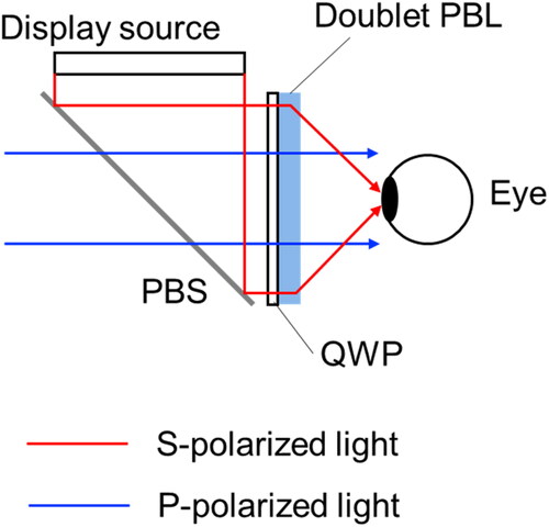
Using the polarization selectivity, a geometric phase doublet lens, or a doublet PBL has been proposed. It functions as either a lens or a transparent window depending on the input polarization. shows the principle of a doublet PBL [Citation32]. The proposed doublet lens is composed of two PBLs having the same focal length. A right-handed circular polarizer is placed between the two PBLs. The right-handed circular polarizer changes any input polarization to RCP. It consists of a linear polarizer and a QWP, as shown in . Both PBLs function as a converging lens for RCP.
Figure 19. Principle of geometric phase doublet lens, or doublet PBL.
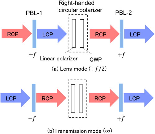
When an RCP input impinges on PBL-1 as shown in , it is converged () and converted to LCP after passing though PBL-1. It is then converted to RCP by the right-handed circular polarizer. This RCP is converged (
) and converted to LCP after passing through PBL-2. Because PBL-1 and PBL-2 have the same focal length, the focal length of the doublet PBL is half of that of each PBL (
).
On the other hand, when an LCP input impinges on PB-1 as shown in , it is diverged () and converted to RCP after passing though PB-1. It is then converted to RCP by a right-handed circular polarizer (RCP is regenerated from RCP). This RCP is converged (
) and converted to LCP after passing through PBL-2, so that the power of two PBLs are canceled, i.e., the focal length of the doublet PBL is infinity (
). Thus, a doublet PBL functions as a lens for RCP and as a window for LCP.
To fabricate PBOEs, photo-alignment technology and interferometry are used. and show the setups of the interferometry for PBD and PBL, respectively [Citation33]. Polarization interference with orthogonally circular polarizations is required, and it results in linear polarization fringes with rotating polarization axes [Citation34,Citation35]. A linearly polarized laser beam is expanded and split into recording and reference beams using a nonpolarizing beam splitter (NPBS). The beams are orthogonally and circularly polarized by QWPs before they recombine and hit the photo-alignment layer. The exposed photo-alignment layer orthogonally aligns the LC director to the exposed linear polarization.
Figure 20. Optical setup of interferometry for PBL.
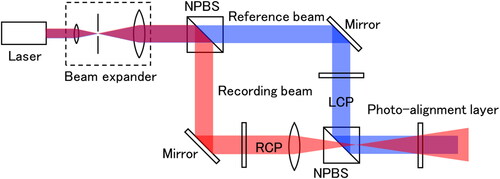
Figure 21. Optical setup of interferometry for PBD.
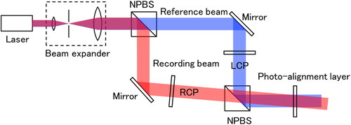
In the setup for the PBL, the recording beam passes through a focusing lens, as shown in [Citation31]. The interference concentric fringes of linear polarization with rotating polarization axes are exposed in the photo-alignment layer. According to the exposed linear polarization fringes, the LCs in the photo-alignment layer align with the rotating directors along the radial axis. Thus, LC director configurations that satisfy EquationEq. (15)(15)
(15) are generated, and the LC layer functions as a lens.
In the setup for PBD, the recording beam is tilted with respect to the reference beam, as shown in [Citation33]. The interference linear polarization fringes along one dimension with rotating polarization axes are exposed in the photo-alignment layer. According to the exposed linear polarization fringes, the LCs in the photo-alignment layer aligns with the rotating directors along one dimension. Thus, the LC director configurations that satisfy EquationEq. (19)(19)
(19) are generated, and the LC layer functions as a deflector.
Interferometry is useful for recording arbitrary wavefronts and generating corresponding patterns for PBOEs. However, it is susceptible to environmental disturbances and requires a coherent light source. Single-exposure fabrication where linear polarizations are patterned using a spatial light modulator (SLM) has also been proposed, but the resolution is limited by the pixel density of the SLM [Citation36].
5.2. Reflective polarization volume gratings
Kobashi et al. proposed PBOEs using cholesteric LCs (CLCs) or reflective polarization volume gratings (PVGs) [Citation37]. PVGs can be regarded as polarization-selective holographic gratings. They are based on patterned CLCs. CLCs have a spontaneous twist with a helical pitch In a PVG, another periodic structure is induced in the horizontal plane with the in-plane periodicity
as illustrated in [Citation38].
Figure 22. Director configurations of PVG.
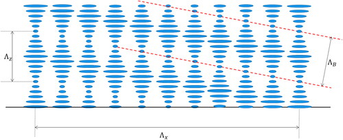
Bragg diffraction can be established when the medium is thick enough to generate adequate periodical refractive index planes. The Bragg pitch is given by
(21)
(21)
where
and
is the helical pitch of CLCs due to the head-tail symmetry of the director. PVG produces Bragg diffraction for a circular polarization having the same handedness as the helix.
The PVG allows for semitransparent devices that function as a reflective deflector for the circular polarization of one handedness and as a transparent window for the circular polarization of the opposite handedness. If the Bragg surface is curved, the PVG functions as a concave mirror, and is also called a CLC lens.
5.3. Proposed technologies that use PBOEs
5.3.1. Compact near-eye display with depth adaption using PVGs and passive PBLs
Lee et al. proposed a compact see-through near-eye display having depth adaption with PVGs and a stack of passive PBLs [Citation33]. Fast depth adaption of an image can be achieved using PBLs. The combined use of PVGs and PBLs makes possible a compact optical design with depth control of the display content to counter the VAC.
shows the optical design of the proposed compact, see-through near-eye display. The light source generates uniform light, which is reflected by a polarizing beam splitter (PBS) toward an LCOS panel. The displayed content is then reflected toward a QWP to convert the linear polarization to circular polarization. The PBL stack consists of multiple passive PBLs with PRs that switch between multiple focusing powers. The light is then passed through a PVG due to the selectivity of the polarization. After the light is reflected by the concave mirror, the handedness of the polarization is reversed and then deflected by the PVG into the waveguide. The second PVG deflects and guides light into the viewing region.
Figure 23. Compact HMD for AR with PBLs and PVGs.
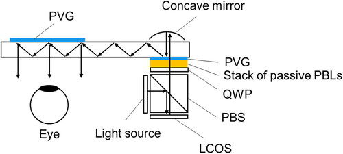
The combined use of the PVGs and PBLs allows for a compactly designed see-through near-eye display with depth adaption. Fast depth adaption of the image was achieved using PBLs with appropriate additive light field rendering. The light field was reconstructed by assigning computationally generated 2D images to corresponding sub-frames with different two depths. The device was set up to generate a switching of 1 D at a 60 Hz frame frequency. The two subframes reproduced a depth adaption of 1 D. It was confirmed that the user could choose to focus on a near or far object with the device.
5.3.2. Doubling the pixel density of near-eye displays using an active PBD
Zhan et al. proposed optics that used fast-switching active PBD to improve the display resolution of VR HMDs [Citation39]. To double the resolution, a display panel was synchronized with the PBD. illustrates the optics that doubled the pixel density. The optics comprise a PBD, a QWP, and a magnifying lens. By applying a voltage to the PBD, the image on the display can be shifted diagonally by half a pixel, as shown in .
Figure 24. Optics that double pixel density.
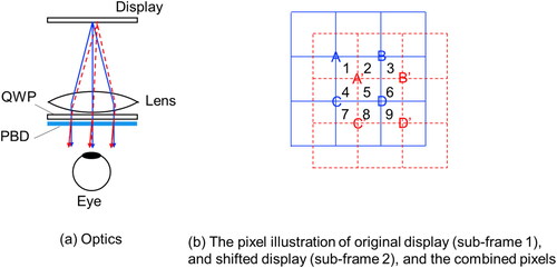
The original panel with square pixels is plotted in solid blue lines, and the shifted panel is plotted in dotted red lines. Pixels A through D are labeled for the original display, while A’ through D’ are labeled for the shifted display. The combined fine grid effectively forms a double-resolution display with the pixels labeled from 1 to 9. An enhanced resolution was demonstrated by switching the PBD on and off, synchronizing with computationally generated sub-frame images.
5.3.3. Wide FOV near-eye display for AR using doublet PBL
Lee et al. proposed an optical combiner for AR by implementing a geometric phase doublet lens, also called a doublet PBL [Citation40]. Depending on the polarization state of light, the real-world scene passes directly through the lens, and virtual images are generated as a function of the positive power of the lens.
When a lens is set in front of an eye in a see-through display, it should function as a lens for the light from a digital display and as a transparent window for the real-world scene. The doublet PBL described in Section 5.1 realizes both of these functions, depending on the input circular polarization.
shows a schematic of the proposed near-eye display, which consists of the doublet PBL, a QWP, a PBS, and a display panel. The real-world scene and the digital image are combined using the PBS. After passing through the PBS, both components are aligned to P-polarized and S-polarized light. The QWP in front of the doublet PBL converts linearly polarized light to circularly polarized light. The QWP axis assigns circular polarization states to each component. Then, the real-world scene is set to LCP and the image from the display is set to RCP. Since the configuration of the entire system is optically equivalent to that of a VR system, it is possible to widen the FOV in the AR HMDs.
Figure 25. Optics of the PB doublet lens for AR.
5.3.4. Foveated display system using doublet PBL
Yoo et al. proposed a foveated display having a single display module based on a doublet PBL. A multi-resolution and wide FOV was simultaneously achieved with temporal polarization multiplexing [Citation41].
The human eye contains the majority of its cone photoreceptors at the center of the macula of the retina, which is called the fovea. [Citation42]. The fovea has high resolving power. The discriminability of the eye is lower in the peripheral region of the retina. Accordingly, high-resolution images should be projected to the fovea. A foveated display system can realize both high resolution and a wide FOV by projecting high-resolution images to the fovea and low-resolution images to the peripheral region.
The doublet PBL functions as a lens or a transparent window, depending on the polarization, as previously described, and it can provide two operating modes: fovea mode for a high-resolution image, and peripheral mode for a wide FOV. The proposed system supports a foveated and wide FOV image simultaneously by superimposing both fovea mode and peripheral mode images.
shows the optical configuration of the proposed foveated display for VR. The display consists of a single display module, two polarization controllers, diverging and converging doublet PBLs, and an eyepiece lens. The display module is based on parallel-beam projection with a collimated beam. The first polarization controller converts an input beam to the RCP or LCP state. The second polarization controller converts the polarization to RCP when LCP light impinges and maintains the polarization when RCP light impinges. These controllers can be implemented using a switchable active-type half-wave plate. Two polarization controllers are synchronized to combine two images in dual operating mode in real time. The diverging doublet PBL functions as a window for RCP and as a diverging lens for LCP. The converging doublet PBL functions as a window for LCP and as a converging lens for RCP. The eyepiece lens focuses a beam on the pupil of the eye.
Figure 26. Foveated display system based on doublet PBLs.
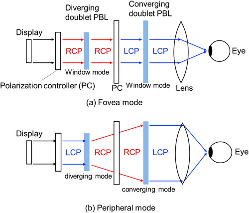
In the fovea mode, as shown in , the first polarization controller changes the beam to RCP. The diverging doublet PBL functions as a window for RCP and maintains the polarization. The second polarization controller converts the polarization to LCP. The converging doublet PBL functions as a window for LCP. Only the eyepiece lens functions as a lens.
In the peripheral mode, as shown in , the first polarization controller changes the beam to LCP. The diverging doublet PBL functions as a diverging lens for LCP and converts the polarization to RCP. The second polarization controller maintains the polarization. The converging doublet PBL functions as a converging lens for RCP. Both the diverging and converging doublet PBLs and the eyepiece lens function as lenses. If the focal length of the converging doublet PBL is identical to the negative focal length of the diverging doublet PBL, the diverging beam from the diverging doublet PBL is converted to a magnified parallel beam by the converging doublet PBL. The expanded beam in the peripheral mode enables a wider FOV than in the fovea mode, but the angular resolution is compromised.
If the two modes are temporally multiplexed at high speed, foveated and peripheral images can be simultaneously observed by the human eye.
5.3.5. Pancake optics for VR using PVGs
Polarization-based optical folding, or “pancake” optics, reduces the thickness of VR HMDs [Citation43]. In conventional HMDs, a bulky lens is used to generate a magnified virtual image of a display, such as an LCD, as shown in . The thick lens is set apart from the display to create a large virtual image. Thus, conventional HMDs are thick.
Figure 27. Pancake optics.
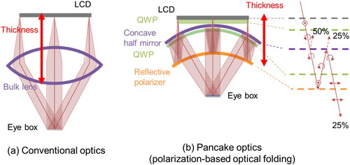
shows the concept of basic pancake optics. A gap is created between the concave half-mirror and the reflective polarizer. The concave half-mirror reflects 50% and transmits 50% of the incident light. The reflective polarizer reflects light of the linear polarization while transmitting that of the orthogonal polarization. QWPs are placed on the LCD and inside the gap.
In pancake optics, light travels as follows: The first QWP on the LCD converts parallel linear polarized light from the LCD to LCP. The second QWP converts LCP back to parallel linear polarized light. The reflective polarizer reflects this linear polarized light, which is then converted to LCP by the second QWP. Then, the concave half-mirror reflects half of the LCP light. The polarization of the reflected light is converted to RCP. Thus, the second QWP converts it to orthogonal linear polarization and then the light passes through the reflective polarizer.
In pancake optics, light traverses the length of the gap three times while occupying only the physical space of one gap length. This enables the LCD to be placed closer to the optics than in conventional optics. However, since the light transmits the concave half-mirror twice and half of the light is lost each time, the overall light efficiency is 25%.
Li et al. proposed a CLC lens for pancake optics [Citation44]. If the Bragg surface is curved, the PVG functions as a concave mirror. shows the proposed pancake optics with a CLC lens. Commercial pancake optics have a flat reflective polarizer and an optical lens, as shown in , although pancake optics with a curved reflective polarizer and no lens are shown in for simplicity.
Figure 28. Proposed pancake optics with CLC lens.
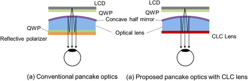
Compared with the conventional design shown in , the proposed pancake optics comprises only three components, including a half-mirror, an optical lens, and a reflective CLC lens, which substitutes for the reflective polarizer and the QWP in the conventional pancake lens, as shown in . Due to the unique chromatic dispersion of diffractive optics, the CLC lens also assists in correcting the chromatic aberration of the system.
The outgoing light from the display panel passing through a right-handed circular polarizer becomes the RCP light. Next, it passes through the half-mirror and is reflected by the broadband CLC lens with the same handedness. Then, the half-mirror reflects the RCP light and converts it to LCP light, which can directly pass through the CLC lens after traveling through the cavity three times. A CLC lens with a diameter of 1 inch and a focal length of 770 mm was fabricated.
To further reduce the thickness of HMDs, Maimone et al. proposed an HMD for VR that combined pancake optics with holographic optics, directional backlighting, and laser illumination [Citation45,Citation46]. Pancake optics reduce the thickness. However, the concave half-mirror still occupies some room. As shown in , thickness due to bulk optics can be reduced by holographic optics. Focusing is performed by holographic optical elements (HOEs) rather than bulk optics. The concave half-mirror is replaced by an HOE. An HOE consists of thin and flat films of negligible thickness and weight. Therefore, thin and lightweight HMDs are ultimately achievable.
Figure 29. Pancake optics combined with holographic optics.
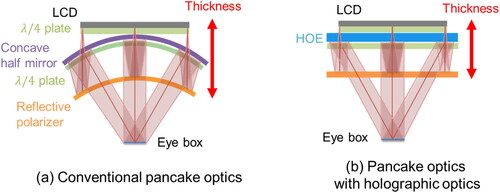
Holographic optics provide an arbitrary deflection of light from a thin and flat surface, but they require wavelength and angle sensitivities. A spectral bandwidth of 0.1 nm to 1 nm is required for optimal performance. This spectrum is much narrower than that of conventional displays, such as LED backlight LCDs or OLED displays. This can be achieved using a laser backlight LCD. The laser backlight LCD can also achieve a wide color gamut, such as the B.T. 2020 color gamut [Citation47].
The application of PBOEs has also been proposed for these ultimately thin and lightweight HMDs [Citation45]. A PVG or a CLC lens was used to add focusing power to the reflective polarizer surface in addition to the HOE. The PVG comprises a reflective polarizer surface and has an aspherical phase profile. The PVG element was designed to correct some optical aberrations of the HOE.
5.3.6. Other technologies for AR/VR HMDs using PBOEs
Many technologies other than those described in this paper have been proposed, such as passive PBLs for chromatic aberration correction [Citation48], Alvarez passive PBLs for a VAC countermeasure [Citation49], and eyebox expansion [Citation50] and gaze-matching [Citation51] for a Maxwellian view.
6. Conclusions
AR/VR HMDs are expected to play an important role in the metaverse. In this review, several challenges were described, such as achieving a wide FOV and high resolution to replicate the real world, freedom from artifacts and the management of VAC for comfortable use, and compactness for all-day use. LC technologies for AR/VR have attracted considerable attention for solving challenges, not only as displays but also as optical elements. Among these technologies, fast response LCDs, called SLC-IPS LCDs, LC lenses, and PBOEs were reviewed in detail. Optics using LCs are quite promising for achieving the HMDs expected for AR/VR.
Disclosure statement
No potential conflict of interest was reported by the author(s).
References
- M. Mon-Williams, J. P. Wann, and S. Rushton, Ophthalmic Physiol. Opt. 13 (4), 387 (1993). doi:10.1111/j.1475-1313.1993.tb00496.x
- D. M. Hoffman et al., J. Vis. 8 (3), 33.1 (2008). doi:10.1167/8.3.33
- M. Oh-e, and K. Kondo, Appl. Phys. Lett. 67 (26), 3895 (1995). doi:10.1063/1.115309
- T. Matsushima et al., J. Soc. Info. Display 26 (10), 602 (2018). doi:10.1002/jsid.708
- G. Tan et al., SID Int. Symp. Dig. Tech. Pap. 50, 624 (2019).
- T. Kurita, SID Int. Symp. Dig. Tech. Pap. 32, 986 (2001).
- T. Shibata et al., J. Soc. Inf. Display 13 (8), 665 (2005). doi:10.1889/1.2039295
- J. L. Ericksen, Arch. Ration. Mech. Anal. 4, 231 (1960).
- J. L. Ericksen, Trans. Soc. Rheol. 5, 23 (1961).
- F. M. Leslie, Q. J. Mech. Appl. Math. 19 (3), 357 (1966). doi:10.1093/qjmam/19.3.357
- F. M. Leslie, Arch. Ration. Mech. Anal. 28, 265 (1968).
- M. Oh-e, and K. Kondo, Appl. Phys. Lett. 69 (5), 623 (1996). doi:10.1063/1.117927
- T. Matsushima et al., SID Int. Symp. Dig. Tech. Pap. 46, 648 (2015).
- T. Choi et al., Sci. Rep. 6 (1), 27936 (2016). doi:10.1038/srep27936
- T. Katayama et al., SID Int. Symp. Dig. Tech. Pap. 49, 671 (2018).
- D. Lanman, and D. Luebke, ACM Trans. Graph. 32 (6), 1 (2013). doi:10.1145/2508363.2508366
- A. Sullivan, Proc. SPIE 5291, 279 (2004).
- A. Maimone, A. Georgiou, and J. S. Kollin, ACM Trans. Graph. 36 (4), 1 (2017). doi:10.1145/3072959.3073624
- T. Ando et al., Proc. SPIE 3956, 211 (2000).
- P. J. Bos et al., SID Int. Symp. Dig. Tech. Pap. 47 (1), 354 (2016). doi:10.1002/sdtp.10678
- G. Kramida, IEEE Trans. Vis. Comput. Graph. 22 (7), 1912 (2016). doi:10.1109/TVCG.2015.2473855
- S. Sato, Jpn. J. Appl. Phys. 18 (9), 1679 (1979). doi:10.1143/JJAP.18.1679
- L. Li et al., Symp. Dig. Tech. Pap. 42 (1), 9 (2011). doi:10.1889/1.3621513
- A. K. Bhowmick et al., Symp. Dig. Tech. Pap. 52 (1), 410 (2021). doi:10.1002/sdtp.14703
- A. B. Watson, J. Vis. 13 (6), 18 (2013). doi:10.1167/13.6.18
- M. Schadt et al., Jpn. J. Appl. Phys. 31 (7R), 2155 (1992). doi:10.1143/JJAP.31.2155
- S. Pancharatnam, Proc. Indian Acad. Sci. 44 (5), 247 (1956). doi:10.1007/BF03046050
- M. V. Berry, Proc. R Soc. London A 392 (1802), 45 (1984). doi:10.1098/rspa.1984.0023
- J. Xiong et al., SID Int. Symp. Dig. Tech. Pap. 50, 620 (2019).
- C. Yousefzadeh et al., Symp. Dig. Tech. Pap. 50 (1), 616 (2019). doi:10.1002/sdtp.12996
- Y.-H. Lee et al., Opt. Data Process. Storage 3, 79 (2017).
- S. Moon et al., Sci. Rep. 9 (1), 6616 (2019). doi:10.1038/s41598-019-42979-0
- Y.-H. Lee et al., J. SID 26, 64 (2018).
- Z. Luo et al., Opt. Express. 30 (20), 36644 (2022). doi:10.1364/OE.473679
- L. Nikolova, and P. S. Ramanujam, Polarization Holography (Cambridge University Press, Cambridge, UK, 2009).
- Y. Li et al., Opt. Express. 27 (6), 9054 (2019). doi:10.1364/OE.27.009054
- J. Kobashi, H. Yoshida, and M. Ozaki, Nat. Photon. 10 (6), 389 (2016). doi:10.1038/nphoton.2016.66
- Y. Lee, K. Yin, and S. T. Wu, Opt. Express. 25 (22), 27008 (2017). doi:10.1364/OE.25.027008
- T. Zhan, Y.-H. Lee, and S.-T. Wu, Int. Symp. Dig. Tech. Pap. 49, 13 (2018).
- C.-K. Lee et al., Proc. IDW, 25, 758 (2018).
- C. Yoo et al., Opt. Express. 28 (16), 23690 (2020). doi:10.1364/OE.399808
- P. Artal, Handbook of Visual Optics (CRC Press, Boca Raton, FL, 2017).
- T. Wong et al., Proc. SPIE 2017, 103350E (2017). doi:10.1117/12.2270266
- Y. Li et al., SID Int. Symp. Dig. Tech. Pap. 52, 424 (2021).
- A. Maimone, and J. Wang, ACM Trans. Graph. 39 (4), 67 (2020). doi:10.1145/3386569.3392416
- S. Komura, K. Okuda, and H. Kijima, Symp. Dig. Tech. Pap. 53 (1), 636 (2020). doi:10.1002/sdtp.15568
- Rec. ITU-R BT. 2020, Parameter values for ultra-high definition television systems for production and international programme exchange (2012).
- T. Zhan et al., Symp. Dig. Tech. Pap. 51 (1), 579 (2020). doi:10.1002/sdtp.13934
- J. Lin et al., Symp. Dig. Tech. Pap. 53 (1), 174 (2022). doi:10.1002/sdtp.15446
- J. Zou et al., Opt. Express. 28 (4), 4921 (2020). doi:10.1364/OE.385540
- J. Zou et al., SID Int. Symp. Dig. Tech. Pap. 53, 624 (2022).