
 ?Mathematical formulae have been encoded as MathML and are displayed in this HTML version using MathJax in order to improve their display. Uncheck the box to turn MathJax off. This feature requires Javascript. Click on a formula to zoom.
ABSTRACT
The wind is one of the most promising green energy resources that replenishes itselves in less than a human lifetime without depleting the planet’s resources. According to the disposition of the blade concerning the shaft, wind turbine can be classified as horizontal axis wind turbine (HAWT) and vertical axis wind turbine (VAWT). In contrast to VAWT, HAWT covers most commercial installations around the globe. However, VAWTs became a promising alternative for areas far away from grid-connected electricity, they have certain drawbacks associated with aerodynamic performance. The present work overviews the magnitude of factors affecting the aerodynamics of typical VAWT, i.e H-Darrieus VAWT and enhancement options associated with cutting edge performance. Additionally, the accuracy of the turbine performance predicting tools through computational investigation and optimization was also assessed. Therefore, the review covered the factors that altered the turbine performance and viable enhancement options studied in the existing literature. Finally, FSI simulation was tics of materials commonly used for turbine blade manufacturing. It was determined that the computational tools employed significantly influence the accuracy of the model, and proper model selection and more experimental validations are compulsory. It was determined that the computational tools employed significantly influence the accuracy of the model, and proper model selection and more experimental validations are compulsory.
1. Introduction
Due to the increase in fossil fuel demand, a large amount of carbon dioxide (CO2) is emitted into space which significantly depleted the environment. Hence, future energy embraces renewable energy resources for sustainable environmental protection and economic development. These are naturally replenished useful energy including solar, biomass, geothermal, hydro, and wind have been used. Among these resources, the wind became the primary energy opportunity for massive electricity generation. Hence, extensive research efforts have been devoted to advance sophisticated technologies to improve energy generation through the wind.
A wind turbine is a rotary machine that transforms the kinetic energy of the wind to mechanical energy in a shaft and then electrical energy in a generator. It was probably originated around 200 BC by ancient Persian (Fleming and Probert Citation1984; Pasqualetti, Richter, and Gipe Citation2004). This was a vertical axis windmill used to grind grain and to irrigate water.
According to rotational axis disposition, wind turbine design can be classified into two main categories, i.e Horizontal Axis Wind Turbine (HAWT) and Vertical Axis Wind Turbine (VAWT). In HAWTs, the rotor blades are perpendicular to the rotational axis (the shaft). Whereas the blades of VAWT are parallel to the axis of rotation. For the last few decades, the major wind energy research activities were regarding HAWT improvements. Through this installed capacity was increased from 25,000 MW to more than 200,000 MW in 10 years (from 2001 to 2010) (Bhutta et al. Citation2012), and it extensively growing to 564 GW in 2018 (IRENA Citation2019). The global wind energy council (GWEC) reports indicating an additional 355 GW of wind turbine expected to be installed in the year 2020 up to 2024 (Update Citation2017).
Figure 1. Characteristic of wind turbines (Ahmed and Gawad Citation2016).
Unlike HAWTs, VAWTs are omnidirectional and can obtain higher capacity factors in near-the-ground installations where the direction of the wind is more erratic than higher altitudes without blades yawing mechanism, generator and gearbox of the turbine can be installed at sea level which is easier for safe maintenance and the best turbine stability during a float. This leads to reduced machine complexity and better scalability to a large turbine size. Although VAWT was the first-ever machine to be used for harnessing wind energy, because of the lack of researchers’ concern it has limited installed share in the global wind energy market (Kalagi, Patil, and Nayak Citation2018). Yet there is an increasing VAWTs demand for small-scale energy supplies away from grid-connected sites such as rural areas and military campuses. Moreover, due to their aesthetic and silent prototype, VAWTs are also attractive for urban wind energy generation.
According to a blade design, VAWTs are classified as drag type and lift type. A drag-type design named it ‘Savonius wind turbine’ the net torque is generated wherever the imbalance of drag force blows over asymmetric blades. However, drag-type VAWTs usually have very low power and torque coefficients as compared to other wind turbines (Roy and Saha Citation2013). On the contrary, lift-based VAWTs named ‘Darrieus wind turbine’ reveal superior aerodynamic efficiency (see ) than other wind turbines (Sun et al. Citation2016). For this fact, lift-type VAWT becomes a renewed interest for micro to mega-scales offshore wind energy generation (Hand, Kelly, and Cashman Citation2021). Nevertheless, lift-type VAWT is incapable of self-starting at a low tip speed ratio (TSR) unless external auxiliary devices are provided. This is because of the complex aerodynamic nature of VAWT caused by many factors including turbine geometry, airfoil type, free stream velocity, incident angle (φ), turbine spacing, angle of attack (AoA), axis eccentricity, blades tip loss, and tip speed ratio (Mohamed, Ali, and Hafiz Citation2015; Naccache and Paraschivoiu Citation2018). These collaboratively affect the turbine self-starting characteristics (Islam, Ting, and Fartaj Citation2008). Hence, attempts are devoted to employing several aerodynamic performance improvement alternatives such as altering the blade profile through CFD and aeroelastic tools, using flow control systems, using high strength to weight ratio material, and so on.
Figure 2. Darrieus types VAWT design concepts (Dabachi, Rahmouni, and Bouksour Citation2020).

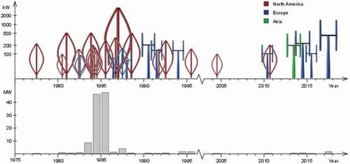
Figure 3. Lift-type VAWTs trends (Möllerström et al. Citation2019).
A wind turbine is a complex system consisting of several components where turbine blades form key structural elements for achieving higher power generation. For this fact, proper choice of material for its component manufacturing must be demonstrated at the beginning of wind turbine development. From the long history of a wind turbine, blades were made of wood (Howard Citation2017) and other local materials. However, to prolong the blade life scientists and engineers are intended to search lightweight and high-strength blade materials for modern structural applications. Among the materials, metallic fiber-reinforced composite (FRC) was superior to those of wind turbine blade designs (Beardmore and Johnson Citation1986; Davies and Chauchot Citation1999; Immarigeon et al. Citation1995; Thomas and Ramachandra Citation2018). For example, In 1956–57, the so-called Gedser wind turbine was built by Johannes Juul with a composite blade supported by steel spars, aluminum shells, and wooden ribs (Abdalrwaf Citation2017). This was the first long-lasting wind turbine that operates for 11 years without failure (Schubel and Crossley Citation2012). However, besides the advantage, synthetic fiber composites become incompatible with the environment of their end-of-life disposal. Because traditional disposal methods, i.e incinerated and landfills (Duflou et al. Citation2012; Kalkanis et al. Citation2019; Psomopoulos et al. Citation2019), impose significant environmental impact (Ramirez-Tejeda, Turcotte, and Pike Citation2017), and most recycling technologies are not yet commercialized.
This paper overviewes the studies done on the parameters that significantly affect the aerodynamic performance of Darrieus type VAWTs. Also, both conventional and unconventional performance enhancement techniques were addressed. Furthermore, opportunities regarding the turbine blade materials which can replace traditional synthetic materials such as glass and carbon fibers with their structural improvement alternatives are also highlighted. Finally, computational techniques for this type of wind turbine are thoroughly discussed, and a case study on the performance of two turbulence models flow characteristics over H-Darrieus VAWT based on the geometry of the NREL baseline turbine was presented.
2. Aerodynamic performance of H-darrieus wind turbine
The aerodynamic performance of H-Darrieus VAWT depends on different design parameters including blade pitch angle, tip speed ratio, airfoil type and configuration, number of blades, blade solidity, and others, In the following few sections, the main factors which will alter the aerodynamic performance of H-Darrieus VAWT are discussed thoroughly.
Pitch Angle (β)
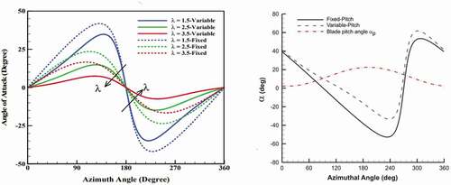
H-Darrieus VAWT can be configured as a fixed pitch (FP) or variable pitch (VP) angle. Compared with the FP-blade, the VP-blade has a wider azimuthal zone that corresponds to higher AoA (Zhao et al. Citation2017) (see . VP-VAWT design strategy is targeted to narrow the azimuthal range of poor performance (Zhao et al. Citation2017). The moment of turbine blades about the pivotal axis became either cycloidal or cyclic motion (Camporeale and Magi Citation2000; Zhao et al. Citation2017). The comparison of the symmetrical blade pitch design strategy of VAWT at main azimuth positions is illustrated in . FP turbines are inherent with lower power efficiency at the rated speed and higher drag coefficient which might affect the self-starting ability of the machine (Dwiyantoro and Suphandani Citation2017; Zhao et al. Citation2018). This is mainly due to large fluctuations when the turbines are in operating conditions (Zamani, Maghrebi, and Varedi Citation2016). In contrast, VP blade designs become handy to alleviate the turbine aerodynamic performance (Guo, Zeng, and Lei Citation2019; Sagharichi, Maghrebi, and ArabGolarcheh Citation2016), and mitigate the turbine blade from catastrophic failure during the turbines are exposed to higher wind loads (Sagharichi, Maghrebi, and ArabGolarcheh Citation2016). The pitching movement of the blades reduces the variation of AoA along the streamwise direction and provides a high torque coefficient (Sagharichi, Zamani, and Ghasemi Citation2018). This leads to the blade reducing the flow separation and offered the turbine for self-starting opportunities (Pawsey Citation2002). VP does not rely on avoiding stall, but optimal TSR must be high enough to maintain a low flow angle which squeezes performance out of the turbine by increasing AoA (Soraghan et al. Citation2013).
Figure 4. Fixed and variable pitch VAWTs configuration (Sagharichi, Zamani, and Ghasemi Citation2018).
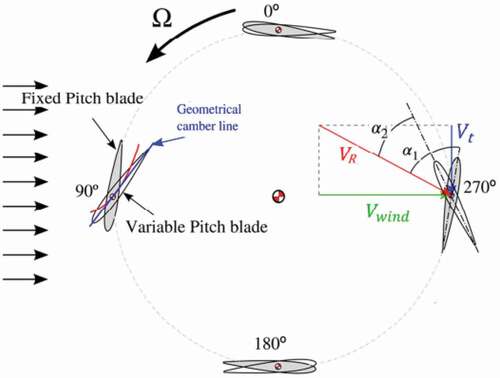
Table 1. Comparison of four different pitching strategies for H-Darrieus VAWT (Zhao et al. Citation2017).
CFD attempts are boosted to explore VAWT performance predictions apart from analytical studies. Through these, the performance of NACA0012 airfoil on a three-bladed H-Darrieus rotor between and
pitch angle was investigated (Rezaeiha, Kalkman, and Blocken Citation2017a). The result showing that the optimum performance of the rotor was achieved at
which was a 2% higher power coefficient (Cp) than
pitch angles. 2D CFD simulation was carried out under NACA0015 airfoil blade VAWT (Elsakka et al. Citation2019). Experimental investigation of NACA0015 in (Douak et al. Citation2018) indicates, at high TSR (λ = 7) and low TSR (λ = 1.5) of VP the torque and power coefficient were increased by 18.5 N and 0.15 respectively as compared to FP angle and provides faster start-up at low wind speed.
The comparative aerodynamic performance of both VAWT pitch angle mechanisms is illustrated in . It implies the VP regime was successful in increasing the peak aerodynamic performance at optimal TSR by 5.4% from 0.37 to 0.39 (Soraghan et al. Citation2013). Nevertheless, with an off-design TSR of 2.5, the power coefficient drops by 26.7% (Elkhoury, Kiwata, and Aoun Citation2015). This implies that the peak in the power coefficient takes place at VP blades. The performance comparisons between FP and VP VAWT with different aerodynamic aspects are illustrated in to . This implies that the overall performance of VAWT improved by VP design as compared to FP once (Mohamed, Ali, and Hafiz Citation2015; Pawsey Citation2002; Sagharichi, Maghrebi, and ArabGolarcheh Citation2016) Because the pitching mechanism maintains the blade at safe AoA and reduces the dynamic stall effect.
Figure 5. Aerodynamic simulations for the test H-Darrieus rotor operating at λ of 4.5 (Soraghan et al. Citation2013), a) AoA b) Induction Factor c) Tangential Force Coefficient d) Normal Force Coefficient.
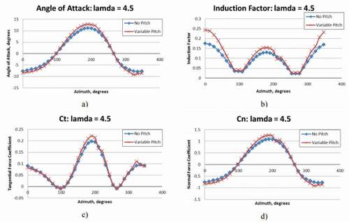
Figure 6. Variation AoA vs azimuthal angle for a λ of 1.5. a) high solidity on the variable pitch (Sagharichi, Zamani, and Ghasemi Citation2018) b) the variation of pitch angle at different azimuth positions vs AoA (Elkhoury, Kiwata, and Aoun Citation2015).
When the wind velocity fluctuates the pitch of the blade would be controlled and allowed to capture the maximum amount of energy by pitching the blades at optimum pitch angles. Hence to find the desired β optimization analysis must be carried out during the blade design. The variation of Cp concerning TSR for seven different β (i.e and
) was studied (Mazarbhuiya, Biswas, and Sharma Citation2020a). The result shows the turbine performance was increased with increasing the β from negative to positive values. Among all considered βs, the optimum Cp (0.27) was obtained when β
at
.
Figure 7. Instantaneous pressure coefficient through mid-plane of an FP and VP angles VAWT at λ = 1 (Elkhoury, Kiwata, and Aoun Citation2015).
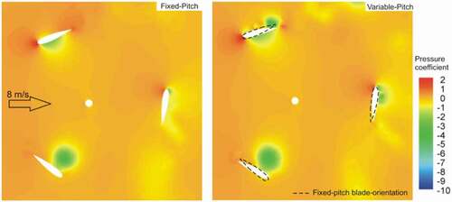
Figure 8. Instantaneous torque coefficients of H-Darrieus VAWT as a function of azimuth position.
2.1. Tip speed ratio (λ)
During the operation of VAWT, the speed ratio inversely varies with the AoA at each rotation. The continuous variation of AoA results in complex flow separation (Jayabalan et al. Citation2017) called a dynamic stall. The effect of TSR on the wake feature of these turbines is studied in Posa (Citation2020). At high TSR, instability of the shear layer generated closer to the flow of leeward and edge ward wakes results in the inversion of freestream wind flow to the downstream direction. This is due to the presence of induction velocity through the flow direction. The influence of induction velocity is the main force that causes to vary the AoA of the rotor blade that leads to stall and reduce the performance of wind turbine (Rezaeiha, Montazeri, and Blocken Citation2018a). Thus, the upstream induction velocity contributed more than half of the total power produced throughout the full cycle.
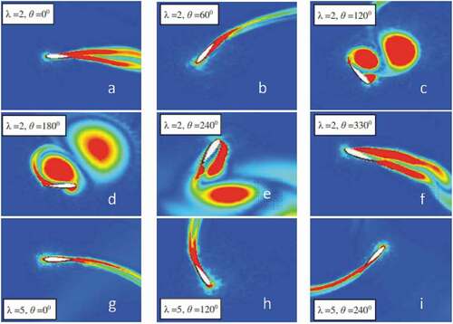
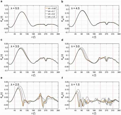
Usually, the turbine solidity inversely varies with operating TSR, the rotor blades do not interact as strongly with much of the airflow passing through the volume swept out by the proceeding blades (Howell et al. Citation2010), which demonstrate dynamic stall which lower efficiency (Mukherjee, Jain, and Saha Citation2016). CFD simulation study on 0.12 solidity H-Darrieus wind turbine shows, at high TSR the flow was more attached to the blades and the AoA was limited below the static stall angle during turbine revolutions (Rezaeiha, Montazeri, and Blocken Citation2018b). While at low TSR as illustrated in the blades have gone through a deep stall in most azimuth position of the rotor. This results in a sudden drop in coefficient moment Cm as illustrated in .
Figure 9. Vortex structure for lower and higher tip speed ratios at different azimuthal positions (θ) (Mukherjee, Jain, and Saha Citation2016).
However, high TSR minimizes the flow separation, a region of backflow that creates a greater blockage effect behind the VAWT (Parker and Leftwich Citation2016). In Ma et al. (Citation2019), URANS simulation was carried out on NACA0022 airfoil blade VAWT to study stall conditions. The result shows that at high TSR, the boundary layer reattached to the blade leading edge which contributed to delay effects on the turbine. This dynamic stall effect over the turbine performance has been suppressed by a stall actuated control device (Ma et al. Citation2019). TSR is not a sufficient parameter to express the dynamic stall behaviors of VAWT. Particle Image Velocimetry (PIV) experiment approved that to accurately understand the flow separation around the leading edge, it is necessary to account for pitch rate effects with TSR (Buchner et al. Citation2018).
Figure 10. Instantaneous moment coefficient for the last turbine revolution for different tip speed ratios using various azimuthal increments (σ = 0.12) (Rezaeiha, Montazeri, and Blocken Citation2018b).
2.2. Type of airfoil
Usually, symmetrical NACA-series airfoils are used for VAWT blade design. However, in the modern aerodynamics of wind turbines, some enhanced airfoils become preferable. For example, the aerodynamic performance of VAWT can be improved by using readymade airfoils such as NLF and hybrid NLF-NACA 4 series for blade design (Tjiu et al. Citation2015a). The performance comparison of 25 different airfoils using CFD based on the URANS equation and SST k-ω turbulence modeling was studied (Mohamed, Ali, and Hafiz Citation2015; Mohamed, Dessoky, and Alqurashi Citation2019). The best five airfoils selected under investigation were LS(1)-0413, NACA63-215, NACA63-415, NACA64-415, and NACA0015. They confirmed these airfoils achieved a high lift to drag ratio with low stall conditions at high AoA when λ was between 0 and 9. Among the five airfoils, NACA63-415 and NACA64-415 show the best aerodynamic characteristics for H-Darrieus VAWT blade design (Mohamed, Ali, and Hafiz Citation2015). Interims of blade shape using LS(1)-0413 airfoil was 16% better performance than NACA0012 (Mohamed, Dessoky, and Alqurashi Citation2019).
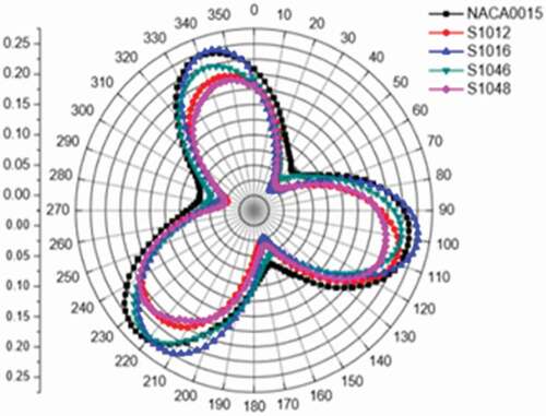
In the recent era of VAWT blade design, S-series airfoils have become the leading inventions, For example, NREL S818 has a partial self-starting capability at low wind speed H-Darrieus rotor, beyond that when it is hybrid with H-Savonius rotor the turbine becomes fully self-starting at any wind speed and azimuth angle (Bhuyan and Biswas Citation2014). Similarly, replacing the symmetrical airfoil blade with S1210 airfoil at optimum blade solidity, the static torque coefficient is positive and four times higher than both cambered and non-cambered airfoils, and the maximum Cp of 0.32 is obtained for rotor solidity of 1.0 and wind speed 5.7 m/s, in which the turbine can develop standalone energy generation (Singh, Biswas, and Misra Citation2015). S1046 has a 26.83% higher power output coefficient and 10.87% higher efficiency than traditional symmetrical airfoils used in H-Darrieus VAWT (Mohamed Citation2012). A 2D CFD analysis on the H-Darrieus rotor having S815 and NACA0018 airfoils shows the stall AoA in the S815 rotor was as high as 9.95° than the NACA0018 blade and exhibited higher performance at optimal wind speed (6 m/s) (Sengupta, Biswas, and Gupta Citation2017). The aerodynamic performance of two different unsymmetrical airfoil blade profiles (S815 and EN0005) was compared using 3D CFD simulation for improving H-Darrieus rotor performance (Sengupta, Biswas, and Gupta Citation2016). It was found that the S815 blade shows a higher velocity difference between suction and pressure sides (i.e. 7 m/s which was 3 m/s higher than EN0005 blade) which reveals better influence for the rotor performance improvement. The performance of S-series airfoils was compared with NACA0015 airfoil (Cao et al. Citation2018). The result shows at low TSR (λ = 4) NCAA0015 revealed higher performance than S1012 airfoil. The aerodynamic performance of 24 different symmetric and asymmetric airfoils was studied using CFD based on k-ε turbulence (Hashem and Mohamed Citation2018). The result shows at low TSR (λ = 4) S1046 airfoil performs with the highest power and torque coefficient over other airfoils under investigation.
Figure 11. Airfoil performance evaluations, a) instantaneous rotor torque coefficient as a function of the blade at the midsection azimuth coordinate of NACA0012airfoil blade(Castelli et al. Citation2013) b) instantaneous best airfoils torque coefficients different family of an airfoil at 4 tip speed ratio (Mohamed, Ali, and Hafiz Citation2015; Mohamed, Dessoky, and Alqurashi Citation2019).
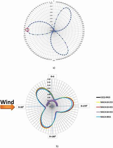
Figure 12. Comparative performance of NACA0015 to four S-series airfoils at different azimuth angles (Cao et al. Citation2018).
2.3. Number of blades (N)
Many scholars proved that the highest performance of the wind turbines was obtained at the three blades (Rezaeiha, Kalkman, and Blocken Citation2017a; Sunny et al. Citation2018). Based on the tangential force generated (Sunny et al. Citation2018), NACA0015 was screened as the best airfoil over all non-cambered airfoils which were supposed to design two, three, and four-bladed Darrieus wind turbines. 2D aerodynamic simulations based on the k-ε model at 10 m/s wind speed and rotor speeds of 4 rad/s, 6 rad/s, and 8 rad/s were studied. The aerodynamic performance of three blades wind turbine was increasing with the rotational speed and highest at 8 rad/s hence maximum torque. While four and two-bladed wind turbine shows moderate and lowest performance (are not efficient to provide an optimum amount of power at low wind speed) at the same aerodynamic conditions, respectively. The performance prediction of three, four, and five-bladed Darrieus type VAWT were studied at constant free stream velocity (Castelli, De Betta, and Benini Citation2012). The 2D-CFD result shows that the performance of the four and the five-bladed turbine was 5% and 15% respectively lower than the three-blade rotors.
2.4. Turbine solidity (σ)
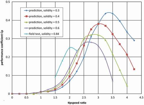
When the diameter of the rotor becomes wider, the vortex wake, drags coefficient, and stress on the blade become reduced (Salman and Bdaiwi). Because the solidity of the blade significantly increases with larger rotor diameter span length as a result the optimum power coefficient decreased at higher TSR (Li et al. Citation2017). In Subramanian et al. (Citation2017), the comparative effect of solidity on the performance of 1 KW VAWT of non-cambered airfoils, NACA0012, NACA0015, NACA0030, and AIR001, blades were studied using 3D-CFD simulations with transition SST and SST-k-ω turbulence model. The result shows that the NACA0012 airfoil has the highest performance at the lowest TSR (λ) under the three-bladed VAWT. And also the performance of the blades is increased with solidity and reaches the maximum value at high TSR, while the power coefficient was dropdown beyond pick point (Douak et al. Citation2018; Subramanian et al. Citation2017) because of large solidity leads to undesirable vibration.
Figure 13. The effect of solidity on Darrieus peak efficiency (Kirke and Lazauskas Citation2011).
2.5. Control methods employed
Controls of the wind turbine are fundamental to increase the wind power capture and reduce harsh operational conditions such as vibrations and total damage during off-design and extreme winds. Hence for regulations, active control systems are commonly used in larger HAWTs, whereas passive control systems such as blade pitching are often used in VAWTs. The blade pitch control mechanism must be designed to achieve a certain range of angles of attack during most of the cycles. The four-bar linkage mechanism controls the blade orientation related to the tangential direction to modify the angle of attack which is used to vary the blade pitch angle through the whole cycle. It allows output power up to 60% at TSR. A four-bar linkage mechanism (Kiwata et al. Citation2010; Sagharichi, Zamani, and Ghasemi Citation2018), shown in , is the common passively aerated control system provided in a variable pitch VAWT. These control systems consisted of spools rotating on the cam (Sagharichi, Maghrebi, and ArabGolarcheh Citation2016). The pitch angle will be determined according to the eccentricity between the axis of rotation and the cam. This blade pitch control largely depends on the placement of moving rods hinged to the blades.
For better self-starting, the blade pitch amplitude should be large enough and the moving rods hinged near the trailing edge of the blade.
And to achieve maximum power, moving rods should be hinged near the place, where the fixed rods have been hinged to the blade.
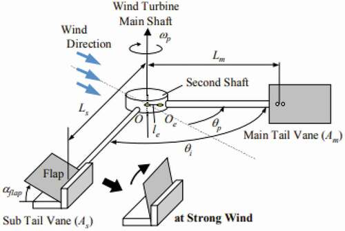
The four-bar linkage mechanism described in Yamada et al. (Citation2012) the performance of a variable-pitch VAWT with double tail vanes installed on the eccentric link lever which can prevent the turbine during storming wind conditions.
Figure 14. Four bar linkage mechanism in H-Darrieus wind turbine a) 2D view (Kiwata et al. Citation2010), and the 3D view (right) (Sagharichi, Maghrebi, and ArabGolarcheh Citation2016; Sagharichi, Zamani, and Ghasemi Citation2018).
Figure 15. Schematics of the over-speed prevention device using double tail vanes for variable pitch VAWT (Yamada et al. Citation2012).
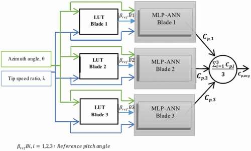
Due to the aerodynamic complexity of VAWT, recently more sophisticated active control systems have emerged since mechanical braking mechanisms are not sufficient to maintain the turbine at rated power. Magnetically-suspended vertical axis wind turbine pitch control system designed by (Shuqin (Citation2011) automatically adjust the blade angle of attack at different azimuth position and alleviate the turbine efficiency. This provides the turbine to minimize the starting torque at low wind speed and self-started. Even though the variable pitch generates higher power than a fixed-pitch VAWT configuration but is not still the optimal mechanism (Hwang et al. Citation2006). This can be improved by a rotary encoder to sense the azimuth position of blades separately at each time step. demonstrates through the pitch control system, the servo motor can transmit its rotating force directly to the blade by linkage, and the changing ratio of the blade pitch angle can be increased by shortening the linkage length (Hwang et al. Citation2006). This makes it possible to respond rapidly at high-speed rotation and increase the power output up to 60% higher than the fixed-pitch bladed rotor. The variable pitch controller Multilayer Perceptron-Artificial Neural Network (MLP-ANN) shown in proposed by Abdalrahman, Melek, and Lien (Citation2017) which operates based on a neural network reveals a 25% higher power coefficient than conventional proportional integral derivative (PID) controlled system.
Figure 16. Sensor and actuating systems layout for individual pitch control system (Hwang et al. Citation2006).
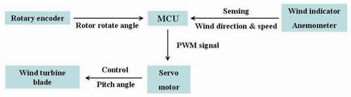
Figure 17. MLP-ANN variable pitch control system (Abdalrahman, Melek, and Lien Citation2017).
2.6. Blade weight
Studies show a denser material used in wind turbine blades leads to a higher frictional effect on the hub bearing which results in reduced efficiency (Ozdamar, Mertcan, and Ozdamar Citation2018). In contrast, the turbine with lighter density blade material will be able to spin faster, creating greater force on the shaft and thus making the generator turn faster and generate more voltage for electricity production (Yee and Long). Under the condition of constant load torque, the energy efficiency of straight-bladed VAWT was almost independent of the wind cycle and the moment of inertia (Hara, Hara, and Hayashi Citation2012). However, under variable wind conditions, even if the frictional loss is neglected so that the higher the weight leads to the higher inertia, and more energy will be invested in acceleration and this is a loss.
3. Performance enhancement options
The aerodynamic performance of H-Darrieus VAWT can be enhanced through the conventional design or by employing new approaches such as:
Geometric alteration such as new airfoil (Bhuyan and Biswas Citation2014; Mohamed Citation2012; Mohamed, Ali, and Hafiz Citation2015), optimum blade shapes (Lositaño and Danao Citation2019; Wang, Wang, and Zhuang Citation2018), employing flow augmentation devices (Kim and Gharib Citation2014, Citation2013; Wong et al. Citation2017);
Employing advance and efficient materials and manufacturing methods, such as light composite and natural fiber reinforced composites materials (Hamdan and Mustapha Citation2017; Kalagi, Patil, and Nayak Citation2018);
Utilize advance flow control devices and schemes such as vortex generators (Gao et al. Citation2015; Wang et al. Citation2017), variable pitch (Abdalrahman, Melek, and Lien Citation2017; Hwang et al. Citation2006; Kiwata et al. Citation2010);
3.1. Thick airfoil blades
A blade’s thickness can influence the performance of VAWT. Usually, symmetrical NACA-series airfoil blades are more streamlined characteristics that accelerate flow separations. However, thicker airfoils provide a better stall at high solidity turbine, improve the structural strength of the blade with an increase in the dead weight of the rotor. Airfoil with the least thickness provides high lift to drag ratio (Jahanmiri, Shooshtaryrezvany, and Nirooei Citation2016). At the same geometric AoA NACA0012 aerofoil performs better than the NACA0022 (Danao, Qin, and Howell Citation2012). The thickness effects of four symmetrical airfoils (NACA0012, NACA0015, NACA0018, and NACA0022) were investigated (Reddy and Kumar Citation2014). It was confirmed that NACA0025 reveals the best performance over the other one. This could be the effect of the blade’s interaction with the large vortices generated by other blades during rotation. A typical thickness effect of 126 airfoils was studied at low TSR (Tirandaz and Rezaeiha Citation2021). Among these, NACA0018 to NACA0024 became optimal airfoils for VAWT blades with increasing the maximum thickness from 18%c to 24%c when a slit λ was declined from 3 to 2.5. Also, the H-Darrieus rotor with asymmetrical airfoil, NACA 63–415 with a relative maximum thickness of 0.3, blade maximizes CP at low wind speed (6.0 m/s) and low λ (2.4) (Mazarbhuiya, Biswas, and Sharma Citation2020b).
3.2. Helical blades
Due to adverse dynamic pressure gradients, high flow separations have occurred from the tips of the rotor blade. Hence, blade tip optimization alleviates the stall AoA which vanishes the flow separation. In this regard, The 2D CFD simulation was done for performance enhancements of H-Darrieus VAWT with trailing edge blade twists angles ( upto
) (Mazarbhuiya, Biswas, and Sharma Citation2020c). It was confirmed that the rotor blade at a
twist angle reveals the maximum CP (0.171) at low wind speed (6 m/s) and TSR (2.4). The 2D-CFD H-Darrieus rotor with a
blade twist angle at a trailing edge up to 10% of the chord was studied (Gupta and Biswas Citation2010). The result shows an approximate self-starting of the rotor was obtained for blade azimuth position of ≥90° with the operating wind velocity of 9 m/s at chord Reynolds number of 6.125 × 10⁴. A similar investigation was conducted while 3D geometry with a two-bladed rotor (Biswas and Gupta Citation2014). It attributed delayed stall AoA (
higher than untwisted) which accelerates the flow on the suction side and produces non-zero lift higher than untwisted one.
3.3. Blade leading edge serrations
Leading-edge serration effectively reduces the boundary layer flow separation and is allowed to accelerate the flow from the pressure side to the suction side of the slot (Mohamed et al. Citation2020). It improves the power outputs of VAWTat low TSR (Lositaño and Danao Citation2018a; Wang and Zhuang Citation2017). It was applied in the H-Darrieus rotor with NACA0018 blade and the flow separation was reduced through the grooved section and the power coefficient was 18.3% higher than the baseline blade (unserrated NACA0018 blade) (Wang, Wang, and Zhuang Citation2018). However, this method was also implemented in a 5 KW H-Darrieus with NACA0025 airfoil blade against a massive vortex flow and leads to poor performance (Lositaño and Danao Citation2019). A serrated blade in a VAWT generates high turbulence instead of containing or decreasing it as was presumed (Lositaño and Danao Citation2018). Hence the concept of leading-edge serration is somehow a contradicted idea and needs more investigation.
3.4. Turbine twin configuration
The performance can also be maximized by optimizing the H-Darrieus turbine configuration through a wind farm. The effects of twin configuration on VAWT studied in Peng et al. (Citation2020) maximize the CPavg by 13% than standalone once. Performance of clusters of two, three, and nine co-and counter-rotating VAWT turbines in parallel and oblique configurations were studied using CFD at low TSR (2.6) (Shaaban, Albatal, and Mohamed Citation2018). The result shows in the two turbine parallel clusters with counter-rotating turbines achieved 16% higher performance than stand-alone, while in the three and nine turbine cluster only one turbine was counter-rotating and reveals 30% and 28% higher performance than the standalone turbine configuration respectively. And also the configurations of the turbines’ cluster, , affect the turbine performance (Shaaban, Albatal, and Mohamed Citation2018). CFD simulation result shows configuration represented in c has a better average CP at the low spacing between the turbines. Even though, the highest CP was less than that of the single isolated turbine by 3.1%.
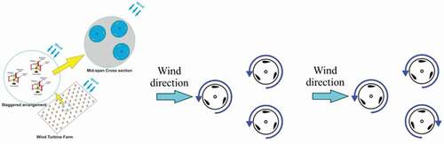
Figure 18. Staggered arrangement of H-Darrieus turbine in a wind farm a) flow domain b) all turbines rotating in the same direction c) One turbine counters rotating.
3.5. Employing flow augmentation devices
Placing the H-Darrieus turbine in the convergent duct can increase the upstream wind speed near the blades (de Santoli et al. Citation2014). According to the CFD investigation carried out between 2 m/s and 12 m/s inlet wind speed, the result shows 32.2% and 30% wind speed enhancement respectively in the middle of the duct. Similarly, the power generated at 8 m/s and 15 m/s was maximized by 125% and 30%, respectively. The reason for low speed and power amplification at high wind speed was due to higher pressure loss at a corresponding flow. Placing a straight plate deflector upstream side of the H-Darrieus turbine enhances efficiency (Kim and Gharib Citation2014, Citation2013). This significantly increases the streamwise local wind velocity which leads to upgrade the angular speed of the rotor while the change of angle of attack was minimized from the no-deflector case. Providing flow augmentation devices such as duct, stator, diffuser, and guide vanes can increase the incoming wind speeds which significantly improve the performance of the turbine (Wong et al. Citation2017). Most of these devices are installed at the upwind side of the turbine and used as shields to reduce the negative torque created on the VAWT, guide the flow to a better angle of attack, increase the wind velocity towards the turbine blade. The blades are configured as cantilever support with or without guy wire at the top of the main tower, while the aerodynamic braking system is mounted near to the ground on the support bar (Tjiu et al. Citation2015b). Cyclonical surface wind lens configuration of S1046 airfoil blade with a diffuser significantly improves the performance of VAWT than traditional orientations (Hashem and Mohamed Citation2018).
3.6. Smart rotor and control schemes
When the turbine spins, the angles of attack (AoA) change continuously and each blade generates its maximum power at the front and rear side of the cycle. This is highly experienced in resonance which leads the turbine to pulse. Due to this reason, an active controlling system such as a braking system is used to regulate the H-Darrieus turbine from a long time spinning. The influence of upwind pressure around the leading edge was larger than the downwind effect on the trailing region of the blade (Li et al. Citation2016). This can be reduced by spanwise extension of the turbine blade, designing a more streamlined support structure and arms, and by extending the rotor diameter with a variable pitch blade (Arab et al. Citation2017). Active pitch controlling systems such as multilayer perceptron artificial neural network (MLP-ANN) individual blade pitch controller provide 25% output power enhancement than constant pitch operated turbines (Abdalrahman, Melek, and Lien Citation2017). The automatic optimization platform (VBPAOP) control system generated in Li et al. (Citation2018) improved the self-starting capability.
3.7. Blade materials
Wind turbine blades are the most important and expensive part of wind turbine components (Mishnaevsky et al. Citation2017). These parts are exposed to diversified load conditions such as gravitational forces, dynamic-wind force, and cyclic load (Thomas and Ramachandra Citation2018), which sever the structural dynamics of the rotor blade (Hameed, Afaq, and Shahid Citation2015). For this reason, lightweight and high-strength materials must be considered during the structural development process to meet the structural requirements of the blade (Muzammil et al. Citation2019; Park Citation2016; Tarfaoui, Shah, and Nachtane Citation2019). To capture high energy and assure low starting speed, employing light-weighted blades can easily rotate and harness the incoming wind speed to the required form of energy. And to protect from any structural damage, typical blade materials must have high stiffness and yield strength. For this fact, proper choice of material for its component manufacturing was demonstrated at the beginning of the history of wind energy development. In the ancient era, wood was considered a common wind turbine blade material (Howard Citation2017). However, due to the nature of high moisture absorption woods are poor in structural performance. Hence, this section highlights the wind turbine blade materials used in the previous era and the future replacement opportunities for the novel blade design.
Figure 19. Key elements to be considered during wind turbine blade materials selection (Zangenberg, Brøndsted, and Koefoed Citation2014).
3.7.1. Synthetic materials
According to the origin, wind turbine blade materials can be categorized as synthetic and natural composites. Among synthetic materials aluminum alloy, glass fibers, and carbon fiber composites are widely used materials for wind turbine blade applications (Kalagi, Patil, and Nayak Citation2018). Aluminum alloy has a better strength-to-weight ratio than glass fiber and carbon fiber (Nader and Jendoubi Citation2018). The comparative performance of straight-bladed VAWT made from Aluminium and the Alumide blade was studied in (Neville Citation2019). The results show that Alumide blade turbine produces higher torque than Aluminium once. Due to its characteristics including low density, high strength-to-weight ratios, and modulus-to-weight ratios, the fiber-reinforced composite (FRC) materials are superior to those of metallic materials (Beardmore and Johnson Citation1986; Davies and Chauchot Citation1999; Immarigeon et al. Citation1995; Thomas and Ramachandra Citation2018). The glass-reinforced composites (GRC) have better mechanical properties, good corrosion resistance, high-temperature tolerance, ease of manufacture, and favorable cost (Eker, Akdogan, and Vardar Citation2006). There are three fundamental ways that carbon fiber may be used in wind turbine blade designs bulk replacement of load-bearing fiberglass materials, selective reinforcement, and cost attractiveness (Veers et al. Citation2003). Besides the advantages, synthetic fiber composites become incompatible with the environment of their end-of-life disposal. Because traditional disposal methods, i.e incinerated and landfills (Duflou et al. Citation2012; Kalkanis et al. Citation2019; Psomopoulos et al. Citation2019), impose significant environmental impact (Ramirez-Tejeda, Turcotte, and Pike Citation2017), and most recycling technologies are not yet commercialized. Hence, attempts are exploring a lignocellulosic material that can replace synthetic composites with better strength and affordable wind energy generation.
3.7.2. Natural Fiber Reinforced composites (NRFC) materials
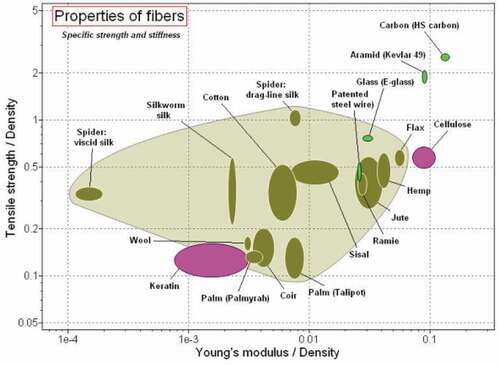
Thermo-mechanical properties, surface treatment, moisture absorption, fibers attachment, availability, durability, and overall cost are the most important screening approaches for natural reinforced fiber composite (NRFCs) during the selection of them for specific structural applications (Lotfi et al. Citation2019). In the previous few decayed NFRCs are becoming suitable for high purpose structural applications buildings, marines, vehicle component designs (Binici, Aksogan, and Demirhan Citation2016; Boumhaout et al. Citation2017; Bravo et al. Citation2018; Florentin et al. Citation2017; Hallonet et al. Citation2019; Hamdan et al. Citation2014; Yoo et al. Citation2019). Because of superior performance in terms of temperature resistance, endurance, long-lasting, and cost attractiveness. Ashby (Ashby Citation2008) investigations illustrated in , the relative performance of various natural fibers compared with manmade synthetic fibers which are frequently used in structural applications. It showed that some plant fibers such as hemp, flax, and jute have better tensile strength than E-glass and steel wire. This is due to the relatively low hydrophobic nature of the fiber.
Figure 20. Comparison of the position of natural fibers against synthetic fibers concerning specific tensile strength and stiffness (Ashby Citation2008).
Studies show natural reinforced fiber composite (NRFC) materials can also replace structural components like a blade. Flax and bamboo reinforced composite materials are dominant in wind turbine blade manufacturing industries. In Setiawan, Al Gifari, and Hamidah (Citation2018), a handmade HAWT blade from bamboo having an average tensile strength of 284.4 MPa starts rotation at 4.6 m/s wind speed, while a standard glass fiber reinforced (GFR) blade is required 4.7 m/s to begin rotation. However, vibration and dynamic instability were observed as drawbacks of the bamboo blade at high wind speed. NRFC blade made from hemp fibers laminated in vinyl ester resin had have resisted the structural impact subjected to low wind speed (Boria et al. Citation2019). The comparative damage pattern of the blade subjected to the lightning strike of flax fiber and glass fiber VAWT blade was studied in (Mat Daud, Mustapha, and Adzis Citation2018). Their microscopic visual result indicates, when both blades were got a lightning strike, flax fiber shows some peeling and some surface breakage while the glass fiber blade experienced burnet. However, a considerable weight and volume of flax are needed than E-glass to pass the same structural requirements (Blanchard and Sobey Citation2019). Hence, physical treatment and other treatment processes are essential to enhance the mechanical properties of natural fibers.
3.7.3. Mechanical properties of natural fibers
Properties of the composites materials depend on various factors, such as type of resin, the origin of the fiber, fiber orientation, manufacturing technique, crystalline index and crystallite size of the fiber, chemical functional groups existing in the fiber, volume and weight fraction of fiber added into the composite, as well as fiber condition (raw or surface treated) (Sanjay et al. Citation2018), and fiber orientation, pressure, cooling speed, temperature and post-curing duration (Cadu et al. Citation2018) are the major decisive parameters affecting the mechanical properties of the fibers. Unidirectional and cross-ply laminates of flax /Elium fiber and flax/epoxy orientation were investigated under 100 KN loading conditions (Cadu et al. Citation2018; Haggui et al. Citation2019). The result indicates that unidirectional composite resin articulation provided higher energy dissipation, a higher life cycle, and comparative stiffness degradation than cross-play orientations (Haggui et al. Citation2019). The tribological behavior of unidirectional flax/polypropylene composite material using, glass fibers as a benchmark was investigated in (Chegdani et al. Citation2017). They used the nanoindentation technique and scratch test under loading conditions. And they conclude as the load increase, dynamic friction coefficient of glass fiber increase while flax fiber reduced, and supplementary behaviors of flax/polypropylene correspond to viscoelasticity/plasticity significantly reduce friction coefficient.
3.7.4. Moisture absorption of NRFCs
The fatigue behavior of uniaxial flax/epoxy composite specimen subjected to 100 kN before and after 23 days immersed in a water bath was studied in Jeannin et al. (Citation2019). Their experimental result shows that
Due to water absorption, the thickness and width are increased by 10% and 3% respectively.
The stiffness of the aged specimen was reduced by 64% and 25% than saturated and dried specimens respectively.
The tensile strength was decreased by 26.5% and 30.3% during saturated and after drying of the specimen.
Hydrothermal aging reduces static rigidity and strength while the fatigue resistance increased with aging and the water absorption can be limited by using coating the specimen.
The hydrophilic property of unidirectional hemp/epoxy reinforcements in a humid environment ranging from 9% to 98% RH (relative humidity) at a constant temperature, moisture absorption, and its effect on mechanical behavior has been studied in Réquilé et al. (Citation2019). Their result shows; 13% reduction of the tangent modulus, longitudinal stiffness reduced, 6.2 ± 1.3 GPa to 3.5 ± 1.2 GPa while despite moisture content the tensile strength was significantly increased and is optimum at 75% RH (3% moisture content).
Also, the orientations of fiber/fiber or fiber/resins are the main cause of moisture absorptions which results in a degradation in the composite structure. The energy absorption intensity and damage resistance capability of hybrid jute/ natural rubber bio-composite materials subjected to low-velocity impact under different layering were studied (Mahesh, Joladarashi, and Kulkarni Citation2019). They conclude that energy absorption and damage resistance of depended on the fiber orientation and plys order in the composite.
3.7.5. Matrixes properties and selection criteria
High moisture absorption, non-uniformity, lower mechanical strength, and matrix in compactness are the major drawback of natural fibers in a structural application (Yıldızhan et al. Citation2018). These can be significantly reduced by using proper reinforcement (Davoodi et al. Citation2011). The common reinforcement compounds used for bio-composites laminate are epoxy, polyester, vinyl ester, etc. Similar to the fiber selection requirements; load resistance, thermal creep, chemical composition are the important characters to select a resistant matrix to protect bio-composite materials from structural failures (Lotfi et al. Citation2019). The comparative energy absorption of Kevlar bio-composite materials using rubber and epoxy matrix under high-velocity loading conditions was studied in (Khodadadi et al. Citation2019). Finally, it was concluded that the epoxy matrix has the lowest reinforcement factor which leads to the lowest ballistic energy absorption, weak load resistance than low hardness (LH), and high hardness (HH) rubber matrix. In contrast, the ballistic absorption of HH matrix was; 19 % and 9 % for two layers, 41 % and 21 % for four layers higher than neat and LH fabrics, respectively. Hence high-quality matrix allowed a better composite interfacial interactions.
3.7.6. Specimen preparation methods of NFRC
The bonding strength between the fiber/matrix pulls out the model influenced by physical dimensions such as fiber length, the thickness of the adhesive layer, diameter, and elastic modulus of fiber and risen (Lau et al. Citation2018). The common specimen manufacturing techniques used in NRFC are spray layup, hand layup, compression moldings, injection molding, filament winding (McGregor et al. Citation2017; Sanjay et al. Citation2018), compression and hand layup molding is used for fabricating woven fabrics, while spray layup and injection molding are used for short fibers manufacturing (Lau et al. Citation2018). In wind turbine blades manufacturing, the blade should follow the standard airfoil profile patterns, and spanwise extensions are provided to have a desired blade size. Wind Empowerment association is highly promoting local manufacturing of small wind turbine blades from NRFC (Latoufis et al.) commonly used for rural electrifications because of the low cost of fabrication and environmentally friendly. Some modern researchers introduced a new mode of blade manufacturing; light resin transfer molding (LRTM) was used to fabricate flax/unsaturated polyester resin blades (Shah, Schubel, and Clifford Citation2013).
3.8. Non-Conventional performance enhancement of Darrieus VAWT
In the modern aeronautical industry, airplane wings are designed with additional aerodynamic structures such as slats and flaps on the leading and trailing edge of the wings respectively. These structures significantly improve the lift force of the blast without affecting the dead weight of the wings. Similarly, researchers coming up with the concept of flaps to solve the self-starting problems of H-Darrieus VAWT at low TSR (El Baz et al. Citation2013). The effect of the inside (Gurney) and streamline flaps on straight blade H-type VAWT was investigated by (Xu et al. Citation2011). The result shows Gurney flap allows a 4% higher power coefficient than the reference NACA0015 blade turbine when TSR was 3.5.
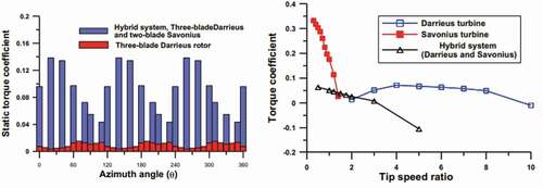
Another alternative recently emerged to enable H-Darrieus WT to self-start and the high power coefficient is to hybrid with another VAWT such as Savonieus (Bhuyan and Biswas Citation2014). This is due to the dynamic stall suppressed by the inside Savonieus rotor and provides starting torque at low TSR (Liu, Yu, and Zhu Citation2019). The comparative investigation is illustrated in , the static torque coefficient of the hybrid system was 15 times higher than alone of three-bladed H-type VAWT (Mohamed Citation2013), getting a quick start. However, the flow penalty may happen when its size becomes larger. The second hybrid system is related to other sources of energy such as solar systems. The wind-solar hybrid system technology is becoming a very interesting research area for mega-scale energy generations such as power plants and grid integrated utilities. These are used for stand-alone energy generations or hybrid energy obtained from the source connected to the DC system and stored in a battery. In Bhuvaneswari and Rajeswari (Citation2013), a hybrid H-type VAWT with an evacuated tube collector was used for the power plant. However, a lack of research is available regarding solar hybrid efficiency enhancement and self-starting issues of H-type VAWT.
Figure 21. H-Darrieus-Savonieus Hybrid WT performance (Mohamed Citation2013). a) Static torque coefficient and hybrid system. b) Torque coefficients for an individual and hybrid turbine.
4. Computational methods for Darrieus vertical axis wind turbine
With growing interest in wind energy harvesting offshore as well as in the urban environment, vertical axis wind turbines (VAWTs) have recently received renewed interest. On the contrary, the complex aerodynamics around these wind turbines hindered and limited the options to enhance the aerodynamic performance. Hence, a comprehensive understanding of the aerodynamics of these VAWT and the relations among several parameters is a vital step.
Fluid flow around the wind turbine is governed by Navier-Stokes equations, which comprised the continuity equation and conservation of momentum equations along each coordinate. As for wind turbine application, the flow pattern is categorized as low Mach flow, nearly 0.1 (Ageze, Hu, and Wu Citation2017a; Hansen et al. Citation2006); thus the incompressible flow models suit well. Therefore, the governing equations will be;
where: : velocity vector,
: air density,
: pressure,
: kinematic viscosity, and
body force vector.
However, as the flow approaches the incompressible limit, it is very difficult to solve the flow equations. To alleviate this numerical difficulty to solve incompressible N-S equations, two common remedies are available: preconditioning and artificial compressibility (Hansen et al. Citation2006). Applying the latter method, the artificial compressibility term will be added to the continuity equation and results (EquationEquation 3(3)
(3) ), pressure-based, or pressure corrected continuity equation as (Equationequation 3
(3)
(3) ), with
is a pseudo speed of sound.
Finally, Equations (1 to 3) will be solved to determine the flow characteristic. Pressure-based coupled solver provides merit of faster solution convergence rate as compared to the segregated algorithm, aside from its high memory requirement.
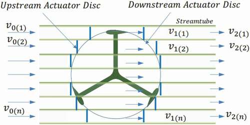
Therefore, based on these relations, computation methods to study and optimize VAWT and the cutting edge method and techniques will be reviewed. The computational method for a wind turbine can be categorized as the Blade Element Momentum method, lifting line, panel and vortex models, generalized actuator disc models, and Navier Stokes based solvers; each theory possesses pros and cons (Ageze, Hu, and Wu Citation2017a).
The key procedures of all computational models to predict performance are described as (Islam, Ting, and Fartaj Citation2008; Kumar et al. Citation2017a).
Calculation of local relative velocities and AoA at different TSRs and azimuthal positions;
Calculations of the ratio of induced to free stream velocity
considering the wake instruction between the blades;
Suitable model selection
Mathematical expressions of normal and tangential forces;
Pre-stall airfoil characteristics’ for the attached regime at different Reynolds numbers;
Post-stall model for stall development and fully stalled regimes;
Finite aspect ratio consideration;
Dynamic stall model to account for unsteady effects;
Flow curvature model’ to consider the circular blade motion
4.1. Blade Element Momentum (BEM) theory
Frequently, the BEM method is used for modeling horizontal axis wind turbines and was originally introduced by Glauert H (G. H., Airplane propellers Citation1963). The theory is based on a one-dimensional classical momentum theory in which forces are distributed continuously in the azimuth direction (Li et al. Citation2014). However, the performance characteristics of VAWT using the BEM model accounting stream tube models also has been the most popular approach to studying its aerodynamics because of their usefulness for giving rough but reasonably accurate performance predictions (Mohammed et al. Citation2019). Hence, this theory is the best-validated model for the performance predictions of both curved and straight bladed VAWTs (Bedon, Castelli, and Benini Citation2013,Hilewit et al., Citation2498-2509, 2019; Saber, Attia, and El Gamal Citation2015). Generally, BEM models can be classified into two categories. i.e cascade model and vortices model. Each of these models has strengths and weaknesses which are presented in this section.
4.1.1. Cascade model
The aerodynamic characteristics of each blade are calculated independently by considering AoA and local Reynolds number in the azimuth of upwind and downwind rotor position (Batista et al.). This model can readily account for the integrated effect of WT parameters such as high solidity, high TSR, blade pitch, flow curvature, and aspect ratio at the same time (Kumar et al. Citation2017a)(see . The Cascade model reasonably predicts the blade aerodynamic force and wakes effect, but it is poor consideration of the dynamic stall effect (Hirsch and Mandal Citation1987).
Figure 22. Cascade model of Darrieus VAWT (Kumar et al. Citation2017a).
4.1.2. Vortex model
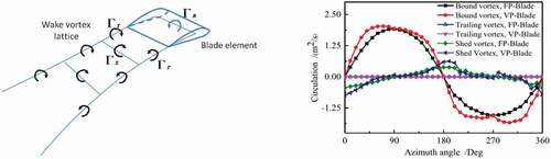
During the turbine rotation, vortex-blade interaction may be attached or detached characteristics. This mainly depends upon the AoA, solidity, and TSR and it has a significant contribution to the performance of VAWT (Chen and Lian Citation2015). The vortexes of WT are mainly originated due to the turbine structures such as support, shaft, blades flow instructions, and other sub-components. The trailing vortex originating in the region of azimuth angle −90° < θ < 90° has a longer dissipation distance at high TSR and a more significant impact on the wake of WT (Yang et al. Citation2017). Due to the complex flow behaviors of VAWT, it is not an easy task to capture the vortex effect by using wind tunnel experiments (Yang et al. Citation2017). Instead of that, CFD and analytical methods are vital to predict the reasonable effect of the vortex on the turbine wake. The intensity of bound vortices shed vortices and trailing vortices of FP and VP straight blade VAWT are presented in b. Except for two azimuth positions of the rotor ( and
), bond vortices of blades were higher than the other twos vortices. This indicates that bound vortices with VP configurations revealed higher lift force than other own vortices and FP cases of vortices (Zhao et al. Citation2019).
The vortex model assumed the flow to be incompressible and inviscid. In this model, the vortex filaments substitute the blades and the vortices in the wakes of blades are calculated by considering blade profile coefficients, relative flows, and AoA (Batista et al.). Several vortex methods i.e. blob vortex (constant vortex generating time interval close to the trailing edges of the blade) (Zannetti, Gallizio, and Ottino Citation2007), vortex filament method (the blades are divided into the number of segments along their span) (Zhao et al. Citation2019), and the strength of vortices filaments are reduced along the span and generate trailing vortices (Zhao et al. Citation2019). To increase the computational effort of the vortices model, the dynamic stall model of the blades was adopted to calculate the lift and drag coefficients (Dyachuk and Goude Citation2015). Hence, this model was effectively incorporating the effect of flow curvature and the dynamic stall effect of VAWT.
Figure 23. Schematics of vortices model. a) Vortex model filaments in straight-blade (Griffith et al. Citation2018). b) Strength of different vortices of FP and VP H-Darrieus VAWT (Zhao et al. Citation2019).
4.1.3. Stream Tube Models
Stream tube (ST) model is a modified actuator disc theory that effectively accounts for 3D effects such as aspect ratio and dynamic stalls of aerodynamic devices (see . However, due to uniform flow assumptions, this model is inferior accuracy at high rotor σ and λ (Kumar et al. Citation2017b). ST model assumptions include:
Irrational and incompressible upstream flow,
The flows over the entire disc are uniform in-stream tube model.
Figure 24. Single-stream tube model (Kumar et al. Citation2017a).
ST models can be classified as single stream tube and Multiple Stream Tube (MST) and Double Multiple Stream Tube (DMST) Models.
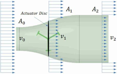
Single Stream Tube Model: This model considers the change in kinetic energy between the upstream and downstream wind as the useful power extracted from the wind. In this model, as shown in , the rotor is represented as an actuator disk inside a stream tube (Templin Citation1974).
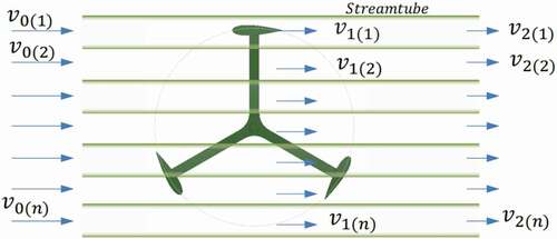
Multiple Stream Tube (MST) Model: An improved version of the single-stream tube model was introduced in Wilson and Lissaman (Citation1974). The swept volume of the turbine was divided into multiple parallel stream tubes as shown in which are aerodynamically independent. The blade element and the moment theory are applied for each stream tube. Rotor power and torque are obtained by averaging the values from each stream tube.
Figure 25. Multiple stream tube model (Kumar et al. Citation2017a).
Double Multiple Streamtube (DMST) Model: DMST model developed by Paraschivoiu (Paraschivoiu Citation1988) divides the rotor into upwind and downwind half considering different induction factors (i.e and
) along each half of the tandems respectively (see . This model is a combination of MST model and double actuator disk theory which incorporates both momentum and BEM theory (Ayati et al. Citation2019; Manwell, McGowan, and Rogers Citation2010). DMST model is the most accurate and optimized model which accounts for the aerodynamic characteristics of VAWT having high σ and low λ (Meana-Fernández et al. Citation2018).
Figure 26. Double multiple stream tube models (Kumar et al. Citation2017a).
Previous studies focus only on operation at the optimal tip speed ratio and there is a lack of analysis of exploiting pitching for any other control objective (Soraghan et al. Citation2013) and there are almost no aerodynamic prediction models publically available for VAWTs with pitching blades (Soraghan et al. Citation2013). A DMST model permits active pitch blade control (Soraghan et al. Citation2013). This is the better numerical model to predict the aerodynamic performance of VAWT considering the blades’ tip-loss at low Reynolds number and TSR (Kumar et al. Citation2017a). It predicted the Cp by 23.1% and 21.8% when Re 1.4 × 10⁵and Re 2.6 × 10⁵ respectively which cannot be achieved in wind tunnel models. BEM relayed the post-stall prediction results with incidences between and
, superimposition of 10% wind fluctuation which allows overcoming the dead band and the rotor achieved self-start (Rossetti and Pavesi Citation2013). In parallel, it was predicted the effect of streamline divergence and relative flow curvature, and the vortices intensity effect at low TSR on the blade using 2D and 3D-CFD analysis respectively. DMST and CFD analysis was used for the performance comparison of the NACA0018 airfoil blade with that of movable airfoil blade at 70% of the cord length away from the leading edge (Beri and Yao Citation2011). They conclude that in CFD lift force generated in the modified blade was a better performance of the turbine at a lower tip speed ratio (< 1) and starts to rotate, and DMST reveals high starting torque or low Cp at low TSR.
4.1.4. Enhanced BEM
The original Blade Element Momentum method was developed with simplified assumptions and assumed a quasi-static/steady flow condition. On contrary, the flow characteristics around actual vertical axis wind turbines tend to be complex and unsteady, therefore additional models have to be included such as wind shear, tip loss factor, dynamic wake/inflow, and dynamic stall.
4.2. Dynamic stall
When the incoming free stream wind is getting strike to straight bladed Darrieus WT, the induced velocity is distributed along the length of the blades (spanwise), blade profile downwind components, and passing through the equator. Thus air passing through the rotor flow towards the tip of blades, and the stream tube passing to the blade tips consequently transfer less moment to the airfoil than those passing at the equator (Paraschivoiu, Desy, and Masson Citation1988). Over the last two decades experimental investigation has been done to understand the dynamic stall characteristics in various aeronautic machines such as helicopters (Carr Citation1988), and H-Darrieus WT (Brochier et al. Citation1986). Now a days the advancement of flow visualization devices such as PIV tends to extend the dynamic stall prediction phenomena (Ferreira et al. Citation2007). However, due to the complexity of dynamic stall behaviors in VAWT, experimental results are inconsistent and lack accuracy, for this reason, attempts are devoted to CFD simulations. While advanced models are required to account for wake interaction to the blades (Richter et al. Citation2011), that may scarify too much computational cost. In Almohammadi et al. (Citation2015), straight bladed H-Darrieus WT, the trailing vortex and leading vortex are formed close to the trailing edge and leading edge respectively and propagated towards each other. Consequently, the two vortexes are merged and formed one larger shed vortex. Hence, the instantaneous lift coefficient shows a large difference in the upwind and downwind sides of VAWT blades (Qin et al. Citation2011). This indicates due to the presence of a dynamic stall the power extracted from downwind side became lower than the upwind side.
4.3. Tip loss factor
According to finite wings theory (Abbott and Von Doenhoff Citation1959), the tip vortices of aerodynamic structures such as airplane wings and WT blades are generated by the pressure difference created between the upper and bottom surface of the blade. Thus, the tendency to trailing vortices from the blade tip, or any point in the blade where flow circulation varied (Zhao et al. Citation2018), thereby reducing the effective blade’s length (Balduzzi et al. Citation2017). The effect may less significant when the turbine aspect ratio is smaller AR < 1. However, for medium AR > 1 (Zanforlin and Deluca Citation2018), and high AR ≥ 6 VAWT (Li and Calisal Citation2010) the tip loss effect on the blade reached 10 % and less than 5% respectively. Similarly, due to the severe influence of tip loss, the torque coefficients become smaller along the blade up span (Jiang et al. Citation2020). As illustrated in a, the vortex at the top tip of the blade is higher and dropped down along the bottom tip. And the corresponding torque coefficients are also presented in . The loss of blade tip can be reduced by bending the blade tips at a certain angle (Li Citation2019).
Figure 27. H-Darrieus blade vortex. a) flow streamlines in the tip region, skin friction lines, and z velocity component on the blade suction surface (Balduzzi et al. Citation2017). b) instantaneous torque at different blade sections (Jiang et al. Citation2020).
4.3.1. Comparison of hydrodynamic models
To investigate the accuracy of hydrodynamic models Ferreira et al. (Ferreira et al. Citation2014) presented a blind comparison of six different models using the analytical method. The models are the Multiple-Stream tube Model (MST), the Double-Multiple Stream tube Model (DMST), the Actuator Cylinder model (extension of the actuator disc model), the U2DiVA code (Unsteady Two-Dimensional Vortices Aerodynamics model), the ARDEMA2D code (based on vortex model), and the CACTUS code (code for axial and cross-flow turbine simulation, a 3D vortex code). To check the accuracy of these models they used different test cases of several TSR, rotor solidity, and fixed pitch angles, included heavily loaded rotors, in inviscid flow. Then evaluating the effect of TSR and solidity on the Cp, assuming these models should give a consistent value of Cp under similar conditions. They used different cases, case A used was at the condition of TSRs of 2.5, 0.5, and 7, solidity (σ) of 0.04, 0.005, and 0.14, and the evaluation criterion was power Cp and torque coefficients (CT). Based on the CP value the models showed good agreement between each other except the MST which showed a deviation from the other models as shown in .
Table 2. Strength and weakness of different analytical models (Batista et al.; Hirsch and Mandal Citation1987; Islam, Ting, and Fartaj Citation2008).
Table 3. Accuracy comparison of aerodynamic models (Ferreira et al. Citation2014).
4.4. Computational Fluid Dynamics (CFD) models
CFD applications developed from the aerospace industry which employs potential flow solvers, to alleviate their limitation, and the use of unsteady Euler solvers emerged. As the computing power grows, the application of full Reynolds Averaged Navier Stokes equations including viscous effects applied for helicopter rotor computations, later on, the full Navier Stokes (NS) computations of wind turbine rotor aerodynamics was presented in Ageze, Hu, and Wu (Citation2017b). NS solver originally developed from an aerospace code solving compressible equations, intended for high speed aerodynamic in subsonic and transonic regimes; apparently, this nature of the code is not compatible with wind turbine application, because of low Mach numbers around the roots of the blades. As the flow approaches the incompressible limit, it is very difficult to solve the compressible flow equation. Two remedies have been suggested by Ageze et al. (Ageze, Hu, and Wu Citation2017b): the first one is preconditioning that changes the eigenvalues of the system of the compressible flow equations by pre-multiplying the time derivative by a matrix. The second method is an artificial compressibility method in which an artificial sound speed is introduced to allow standard compressible solution methods and schemes to be applied for incompressible flows. This method has many merits such as ease of implementation of overlapping grids as the compressible codes, and the main limitation is the problem to enforce incompressibility in transient computations without the need for a huge amount of sub-iterations and the problem of determining the optimum artificial compressibility parameter. The method is well suited for solving nearly incompressible problems often experienced in connection with wind energy. In connection with steady-state problems, the method can be accelerated using local time-stepping, while the method using global time-stepping still is well suited for transient computations.
4.4.1. CFD flow domain
CFD study is also quite sensitive to the flow domain size (the ratio of the side length of flow domain to turbine diameter). Chen et al. (Chen et al. Citation2016) studied the effect of flow domain on CFD accuracy of vertical axis wind turbine, five different ratios (i.e. 10, 15, 20, 25, and 30) were compared. demonstrates the effect of the flow domain ratio on the CT, from the figure it can be seen that the CT value of the rotor is relatively stable when the computational domain ratio is larger than 15.
Figure 28. The flow domain ratio effects on the turbine torque coefficient (Ferreira et al. Citation2014).
4.4.2. Turbulence modeling
Flow around the wind turbine can be fairly considered as turbulent and so including the effect of turbulence in the flow model is mandatory. Several turbulence models are available, such as the Spalart-Allmaras model, two equations k-ϵ model and k-ω model, Reynolds stress model, Detached Eddy Simulation (DES), Large Eddy Simulation (LES) model, and others (Ageze, Hu, and Wu Citation2017a).
The main shortcoming in CFD modeling is the selection of the meshing accuracy, physical model, and turbulence model which results in conflicts and confusing output (Mohamed, Ali, and Hafiz Citation2015). Hence, detailed understandings of CFD points are essential to obtain meaningful results. RANS turbulence model reduces computational time and cost, however, it is not an efficient tool to couture the turbulence intensity caused by adverse pressure gradient (Lanzafame, Mauro, and Messina Citation2014) and considered Reynolds stress tensor proportional to the strain rate tensor which is an invalid computational model for highly accelerated and curvature flow (Mohamed, Ali, and Hafiz Citation2015). Hence, k-ε, kω, SST- kω, LES, and hybrid LES are enhanced RANS tools to developed turbulence modeling in wind turbine and other aerodynamic performance studies. All turbulence models have similar transport equations for turbulent kinetic energy (k) and turbulent dissipation rate (ε), while in the eddy simulation turbulence model, the Prandtl numbers governing the turbulent diffusion and dispassion rate (Ghasemian, Ashrafi, and Sedaghat Citation2017). The k-ε turbulence model is the most common turbulence model used in industrial applications. It can solve the turbulence kinetic energy (k) and turbulence dissipation rate (ε) based on the RANS equation. The renormalization group (RNG) k-ε turbulence model handle some gaps observed in the k-ε turbulence model (Yakhot and Orszag Citation1986), which make it more reliable than the standard k-ε model (Ghasemian, Ashrafi, and Sedaghat Citation2017), while the Realizable k-ε turbulence model provides superior performances for flows involving rotation, boundary layers under strong adverse pressure gradients, separation, recirculation and non-reliance on assumed relationships between Reynolds stress tensor and stress rate tensor (Hashem and Mohamed Citation2018; Mohamed, Ali, and Hafiz Citation2015) the major differences of this families are the determination of Cµ for the standard k-ε model is not constant (Mohamed, Ali, and Hafiz Citation2015). The main problems observed in these models are not efficient to compute near-wall boundary flow with adverse pressure gradients.
When the flow is in the transitional region transitional SST turbulence model corresponds to time step independence became significant (Subramanian et al. Citation2017). The freestream inflow which is far away from the wall boundary is used the formulated SST k-ω turbulence model which can accurately be calculated for the separation (Li et al. Citation2017). Hence, SST k-ω turbulence model can achieve good results because of its capability of capturing proper behavior in the near-wall layers or shear stress transports of the fluid and separated flow regions (Castelli, De Betta, and Benini Citation2012). The three combined models, k-ε and SST k-ω are essential turbulence models to consider both near walls and far wall-flow conditions, The standard k-ε and SST k-ω properly resolve near-wall boundary conditions and the flow separation formed by a free stream inflow far away from the walls respectively (Li et al. Citation2017) with an acceptable computational cost and reasonable accuracy (Almohammadi et al. Citation2013; Nobile et al. Citation2011; Spentzos et al. Citation2005), however it takes too much computational time and high computational space.
4.4.3. Comparison of hydrodynamic models and CFD with experiment
To evaluate the accuracy of hydrodynamic models presented in section 2.3 and CFD (SST k-ω turbulence model) (Delafin et al. Citation2017) studied the comparison of low-order aerodynamic models and RANS CFD for full-scale 3D vertical axis wind turbines. They used a DMST model a free-wake vortex model, and SST k – ω turbulence model, and compared the result with a 17 m vertical axis wind turbine field-tested by SNL. Their result showed among comparisons of the three numerical models SST k–ω turbulence model gives better accuracy than the other hydrodynamics models which can give a fairly good prediction of the turbine CP. However, predictions at low and high tip speed ratios do not have the same level of accuracy.
Figure 29. CFD model comparison of power coefficient CP as a function of TSR and experimental studies results used for H-Darrieus VAWT.
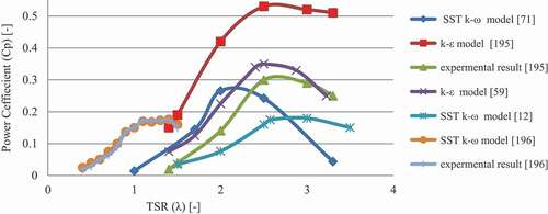
Hence, here the robustness of these models compared to each other is illustrated in . The unique feature of the SST k-ω model over k-ε is allowing reliable power coefficients (Cp) at low TSR (λ) Ma et al (Ma et al. Citation2018). In contrast, the Realizable k-ε model used in M.R.Castelli et al. (Castelli, Englaro, and Benini Citation2011) over predicted the performance and disagreed with experimental and other numerical results.
4.5. Structural models for darrieus VAWT
The structural models will determine the dynamic response of the system for the aerodynamic load. The earliest works tend to use linear beam theories with homogenous properties. As the design of VAWT blades becomes more flexible and increasing its size, classical beam theory may be sufficiently incapable of a model the structural dynamic of the turbine, contrary to the fact that the utilization of more nonlinear beam theory with less assumption is demanded (Ageze, Hu, and Wu Citation2017b). Besides the beam theory (linear or nonlinear) and elements (shell or beam elements) to be employed, there are three frequent discretization methods to model the structural dynamics of the wind turbine (Ageze, Hu, and Wu Citation2017b), that is, modal reduction approach, multibody dynamics (MBD), and finite element methods (FEM).
4.5.1. Finite Element Method (FEM) studies in H-Darrieus VAWT
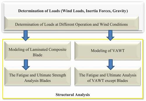
FEM analysis was used in composite blades based on the shell element discretization method which effectively determines the accumulation of ice, mechanical, and hydro-thermal loads (Kong, Bang, and Sugiyama Citation2005). The strain stress characteristics of four different lay up of 1.2 MW blades were studied in Lanting (Citation2012). Their result shows, [0°/±60°/90°] lay-up sequence became the optimal orientation. The centrifugal forces acting on the glass fiber-epoxy blade was evaluated using FEM (Hameed, Afaq, and Shahid Citation2015). The orientation of Glass fiber-Epoxy layers [45°/90°/0°/−45°] with varying thickness of each layer was chosen for the best design of straight blade of a VAWT which reduced the values of both maximum stresses and maximum deflections when compared with Aluminum blade. This method is also used in composite VAWT for fatigue and ultimate strength analyses under normal and extreme wind conditions (Lin, Xu, and Xia Citation2019). Experimental validation of the FEM thermoplastic composite sandwiched 5 KW straight blade design meets the required performance criteria at extreme wind load cases (Brown and Brooks Citation2010).
The upper FEM studies are carried on synthetic and metallic wind turbine blade materials, while this method is also implemented in advanced blade materials such as NFRC. In Park (Citation2016), the structural analysis of the 1 KW flax/ epoxy wind turbine blade was performed and compared with the glass fiber/epoxy blade. The results confirmed an acceptable structural safety of flax-reinforced structures at extreme loading conditions. The comparative structural analysis of aluminum alloy, glass fiber, and hemp fiber composite blades has been investigated at 11 m/s wind speed (Elalaoui Citation2019). The result shows constant stress of 49.92 MPa, and the maximum deflections of hemp fiber were lowest and which beneficial than the two-bladed materials due to their low weight and cost. Bamboo fiber-reinforced has a superior ability to resist wind attacks than GRF blade, which the three-layer structures i.e. outer, middle, and inner skins combinations suppress blade vibration and static loading when the flow reaches the dangerous velocity (Meng and Sun Citation2017).
Figure 30. Structural analysis platform of vertical axis wind turbines (VAWTs) (Lin, Xu, and Xia Citation2019).
4.5.2. Modal approach
When VAWT works in a natural environment, the loads are complicated and variable. The freestream wind load, elasticity force, and inertia forces are applied on the blades of a wind turbine can make the blade and tower deform and oscillate (Feng et al. Citation2018). These lead to the damage of the wind turbine when the exciting force approaches the natural frequency of the turbine. The flap-wise, edgewise, extensional, and torsional deformations vibration analysis of troposkein shape blade has been characterized under stationary and rotating conditions in Hakeem Saleh (Citation2017). The effects of wind speed and shear on the modal response of the lift type VAWT to azimuth position are mainly due to excitation being applied to the tower rather than to the blades and struts (Kusnick and Adams Citation2012). In some other shapes of the blade of VAWT, the blade resonance may be significant for the structural response. This may improve by introducing new materials such as woods that have low density and high yield strength (Yi and Teoh Citation2018). The modal analysis of straight-bladed H-Darrieus WT shown in a was done (Afzali, Kapucu, and Feeny Citation2016). The natural frequency of the rotor can be expressed in Equationequation (4)(4)
(4) .
The turbine response as a function of rotor speed at different blade position length ‘a’ are illustrated in the b, the primary resonance of the turbine occurred at the point where the natural frequency is equal to the rotor speed which the undamped natural frequency. When the rotor reached the critical angular speed the system becomes unstable. Therefore, to increase the natural frequency of the system must be satisfied (Afzali, Kapucu, and Feeny Citation2016).
Figure 31. Modal analysis of straight-bladed H-Darrieus WT. a) blade deflection b) natural frequency.
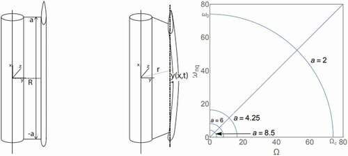
4.5.3. Multibody Dynamics (MBD) Method
The multi-body design approach helps to parameterize different elements of VAWT such as blade mass, the mass of the arms, the size of the tower and optimize the size of linkage mechanisms used for blade pitch controls (Chougule and Nielsen) which are described in sections 2.6 and to specify the characteristics of the generator coupled to other elements of the turbine (Rishmany et al. Citation0000). The effect of the twisted blade turbine system on the mast has been discretized based on a simplified multi-degree of freedom (MDOF) (Verkinderen and Imam Citation2015). Taking the mass of the rotating element into account, ignoring the stiffness, and considered the turbine as a static structure, the stiffness of the mast was characterized under the height of 3 m, 6 m, 9 m, and 15 m. The response of 15 m masts for the first three modes and the system coupled natural frequencies for different mast lengths are presented (Verkinderen and Imam Citation2015) in a and b respectively. The dynamic behavior of the tower and blades of 5 MW H-type floating VAWT has been studied using multi-body kinematics and dynamics analysis (Deng et al. Citation2020). It was determined that the elasticity of the blade and tower has little effect on the dynamic response of the floater. The blade responses are mainly affected by aerodynamic whereas the tower response includes both aerodynamic and wave frequency.
Figure 32. Multi-body dynamics of typical VAWT (Verkinderen and Imam Citation2015). a) FE model of 15 m mast and first three mode shapes. b) Mast, turbine and coupled system natural frequencies for different mast lengths.
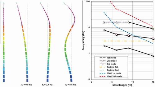
4.6. Artificial Intelligence (AI) method
AI is an imitation of human cognitive processes to create intelligent machines that can simulate human thinking capability and behavior in which machines can execute tasks smartly. It applies superimposed concepts such as machine learning (ML), deep learning (DL), ensemble deep learning (EDL), and many more techniques to understand and solve the actual problem. Whereas, ML is the subset of AI that allows machines to learn from data without being programmed explicitly or assisted by domain expertise. It includes the ability to learn and train a model based on the data and ML algorithms respectively and then evaluate performance to predict the desired output.
In the last few decades, AI was applicable with advanced search engine referral systems (such as YouTube, Amazon, and Netflix), human speech understanding (such as Siri or Alexa), self-driving cars (such as Tesla), and high-level competitive game systems such as chess and Go and the machines became more efficient (Chatterjee Citation2020). Know a day AI also became a promising approach in energy sectors (Bose Citation2017). Because the nature of turbines tends to be complex to increase the power output, next-generation wind energy industries require AI-based system design and monitoring to operate machines efficiently and consistently (Chen et al. Citation2021) which includes structural health monitoring (Reddy et al. Citation2019), design and optimization (Jayabalan et al. Citation2017), wind turbine performance predictions (Papathanassiou, Kladas, and Tegopoulos Citation2001), load and price estimation (Negnevitsky, Mandal, and Srivastava Citation2009), fault detections and monitoring (Saenz-Aguirre et al. Citation2019; Stetco et al. Citation2019), system control and sustain energy output (Saenz-Aguirre et al. Citation2019), etc. Hence, wind turbine designers and engineers must consider multi‐objective optimization algorithms that are essential to identify a trade‐off curve that reveals the weaknesses, anomalies, and rewards of certain targets (Chehouri et al. Citation2016).
Supervisory Control and Data Acquisition (SCADA) is a hardware system used to collect and store high-resolution 10-minute average or one-minute snapshot records of wind farm conditions. It allows AI techniques for analyzing the data’s dependencies among various physical sensors (Viharos et al. Citation2010) through three main steps i.e data-acquisition, pre-processing, machine learning, and finally diagnostic and action can be carried out (Chandrasekhar et al. Citation2021). SCADA systems can be used for both monitoring as well as controlling industrial systems remotely and provides an efficient way for industries to gather and analyze data in real-time (Eriksson Citation2020). This system has been utilized for collecting and storing data from wind farm operations (Martinez et al. Citation2019). To manage power consumption and turbine efficiency, the system may be integrated with turbine control systems to detect downtimes. However, SCADA is mostly used for wind farm label application which needs very expensive system cost. And in most case the system focus monitoring and diagnostics of with limited turbine components such as pitch angle, gearbox, and generator which may not sensitive enough to reflect the change in the WT health state (Liu et al. Citation2019). Hence advanced AI methods such as deep learning (DL) and ensemble deep neural network (EDNN) are supplemented with SCADA to build accurate fault detection models (Liu et al. Citation2019).
Usually, artificial neural network (ANN) algorithms are used to optimize wind turbine components such as airfoil blades (Mortazavi, Soltani, and Motieyan Citation2015; Ribeiro, Awruch, and Gomes Citation2012) and overall enhancement of aerodynamic performance of the wind turbine (Casás et al. Citation2005). ANN was proposed by (Brahimi Citation2019) as a powerful tool to predict the wind speed associated with input layers and hidden layers. The result shows as compared to weather research and forecasting (WRF) this scheme was more flexible interims of accuracy and computational time. The comparative performance of support vector regression (SVR), regression tree (RT), random forest (RF), and ANN was studied for predicting wind energy production (Buturache and Stancu Citation2021). Their result represents ANN delivers an MAE that is 20% smaller than RF, 35% smaller than SVR, and 59% smaller than RT. While its main drawback was the larger training time and computational power invested during the process of determining the best combination of parameters. Ensemble ML was incorporated on 1.5 MW aerostructure simulations of generic HAWT (Clifton et al. Citation2013). It was confirmed that the regression tree method predicts power output with two to three times more accuracy than the industry-standard power curve method, and may be useful for the estimation of power output with a limited input variable (i.e. hub height wind speed, turbulence intensity, and wind shear). The ANN model was developed by (Siavash et al. Citation2021) to establish a relation between inputs (wind speed and duct angle) and outputs (rotor angular speed and power) variables. The result was found to possess better performance than the regression model for both turbine power curve and rotor speed estimation.
ANN, AI based VAWT design, developed by S.Teksin et al. (Teksin, Azginoglu, and Akansu Citation2022) illustrated in has five inputs (AoA, D, V∞, c and, resistance), 10 hidden layers, and one output (the voltage). They were tested each learning algorithms 50 times and the results of these 50 experiments were averaged. It was seen that according to Bayesian regularization regression algorithm analysis, the best performance was obtained with 35 hidden neurons. ANN was developed by K.Ziane et al. (Ziane et al. Citation2021) predicts fatigue life of GFRC blade under extreme environmental conditions (dry and wet). ANN with Cuckoo Search algorithm was pointed out that the better than the backpropagation and particle swarm optimization algorithms in terms of the blade fatigue life prediction because of its simplicity in using mathematical models, as well as its ability to adjust weights without determining a gradient. In some advanced levels of computation, the outputs of one may be considered as the parts of inputs layer for the development of AI, for example, the deflection of GFRC wind turbine blade specimen was simulated using ABAQUS (Supeni et al. Citation2014). The results obtained from the investigation, a load applied and the current was used as inputs to generate an ANN-based design tool for predicting the number of wires needed to restore the original shape of the blade.
Figure 33. The architecture of ANN (Teksin, Azginoglu, and Akansu Citation2022).
Most the reviewed research articles in this sections are the subset of AI (i.e. ML), while in some case they used interchangeably and it may be confusion behind their deference. While the main drawback of AI-based studies is the optimal number of hidden layers (neurons) can be obtained by several trials which are time-consuming during the training process rather than computational cost.
4.7. Fluid-Structure Interaction (FSI) and aeroelasticity of darrieus VAWT
The concept of aeroelasticity is a developed tool in the aviation industry since 1947 as introduced by A.R. Collar, and its application for wind turbine design and analysis begins as late as 1976 by Friedmann (Friedmann Citation1976). However, its application in VAWT simulation is very limited. Aeroelasticity study the fluid-structure interaction interactions of a flexible and moving body. In classical aeroelastic methods, the fluid and structure interaction is treated separately and uncoupled, ignoring the interaction among these domains (Marshall and Imregun Citation1996). As the computing power improved, several integrated approaches developed including inherent fluid-structure coupling. As the fidelity requirement of the analysis increases to include explicit details such as turbulence and wave loadings (Owens, Griffith, and Murray Citation2014), nonlinear composite layered blades, and large deformation (Owens and Griffith), the application of strong fluid-structure coupling is necessary. However, on the contrary, computational efficiency with small compromise on accuracy is also another route of coupling demands, such as introducing a reduced-order model (Ferrari Citation2012).
Flutter or dynamic aeroelastic instability can be a fundamental design consideration for lift-generating structures under aerodynamic loads (Owens and Griffith). This coupling of aerodynamic forcing with a structure’s natural modes can lead to large amplitude diverging motion. Hence, the fluid-structure interaction (FSI) simulation tool for turbine performance studies, combines blades’ structural dynamics and the flow around them. This requires the computation of both the velocity and pressure fields in the fluid domain, simultaneously with the stress and strain fields in the structural domain (MacPhee and Beyene Citation2013). It uses nonmatching discretization of the interface between the fluid and structure subdomains which interpolates the traction and kinematic simulation data was essential for aerodynamics and structural mechanics modeling approaches than the FEM model (Bazilevs et al. Citation2015) and helps to predict structural deflections of blade materials caused by wind flow (Castelli et al. Citation2013). This technique was implemented in 1.2 KW VAWT for the validation self-starting of field test data. Even though these techniques are quite preferable to the individual FEM or CFD system, limited researches are done for vertical axis wind turbines.
Figure 34. Typical Aeroelastic (FSI) based tool.
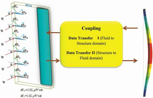
There are two main FSI solution approaches (MacPhee and Beyene Citation2013):
The first is segregated (one-way coupling) fluid-structure solvers and transfers information between the two until convergence is reached. This is numerically unstable while it allows cheaper computation.
The second is a monolithic (two ways coupling) solver which simultaneously solves for the fluid and structural domains and these are robust FSI simulation approaches.
The FSI simulation technique is one of the novel performance prediction methods used in modern mega-scaled wind turbine composite blades. The 5 MW baseline HAWT symmetric fiber glass/epoxy composite blade was considered at 11.4 m/s wind speed and angular velocity of 12.1 rpm, rotor using FSI modeling technique (Bazilevs et al. Citation2011). The critical stress component of the entire blade at 0.7 s was observed in σ22 (0’ fiber orientation) and the maximum stress along the front and rear of the blade was 22.63 MPa and −19.84 MPa respectively. The corresponding flap and edgewise deflections were 6 and 0.3 m respectively.
Similarly, some researchers applied FSI for VAWT analysis. FEM coupled with vortices filament for an aeroelastic structural dynamic of a troposkien blade was presented (Fereidooni, Nitzsche, and Matida Citation2014). The aeroelastic responses of the morphing design concept of the VAWT blade passively control the pitch angle and enhance the self-starting capability of the rotor (MacPhee and Beyene Citation2016). This model saves simulation data to mitigate the loss attributed to vortices loading and blade stall in the region of poor airfoil lift while it is an expensive computational cost. VAWT with an active control system, coupled aero-hydro-servo-elastic simulations have been performed on individual pitch-controlled VAWT (Vlasveld et al. Citation2018). The result illustrated that the dynamic load acting on the rotor was reduced due to the control system employed.
FSI model becomes the preliminary effort for a better understanding of H-Darrieus WT for components elastic deformations and self-starting issues of the turbine (Bazilevs et al. Citation2014). The transient response of this system at inflow wind speed was 11.4 m/s and considers three initial rotor speeds: 0 rad/s, 4 rad/s, and 12 rad/s. The result shows at 4 rad/s values of angular speed became more linearized, the lift force was higher, the rotor naturally accelerated and the tower tip displacement during this cycle was about 0.10–0.12 m. This allows promising for VAWT to self-start.
Figure 35. Typical System coupling. a) one-way coupling (Wang et al. Citation2015) (the left side one) b) Two-way coupling (Rafiee, Tahani, and Moradi Citation2016), (the right side one).
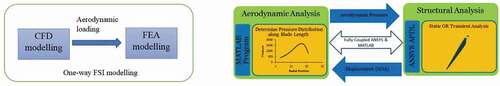
FSI simulation was carried on a 1.2 KW Darrieus baseline wind turbine at 11.4 m/s and 4 rad/s inflow wind speed and the initial rotor speed respectively (Bazilevs et al. Citation2015). The rotor and struts were made of aluminum, and the tower was made of steel. The result shows that as the rotor spins, the structure was not too flexible and the amplitude of tip displacement became approximately 12 cm. Additionally, the rotor speed increased gradually with time step and eventually reaches the speed necessary for efficient operation. For a better understanding and more multi-perspective consideration of turbine blades, modern researchers coming up with sophisticated BEM-FSI coupling simulations. This was done in (Lee, Jhan, and Chung Citation2012) for fiber-reinforced plastic (FRP) composite turbine blades to enhance the optimal performance, designed power capacity at 10 and 25 m/s was 1.3 and 1.66 MW, of a HAWT turbine. Hence BEM result with FSI consideration shows 13.3% and 17% power output delay. To mitigate these design loss they three important measure has been taken i.e. twisting the blade geometry, pitch angle control correction, and adjusting fiber orientation. A synthetic coupling, DMST model-Vortex theory, approach was utilized to investigate the aeroelastic characteristics of H-Darrieus blade considering both stall and post effects (Shams, Molaei, and Mirzavand Citation2019). The result shows that due to the presence of stall and lift force reduction, nonlinear aerodynamics predict the elastic torsion at higher flow velocities to be smaller than the value predicted by linear aerodynamics in which static stall reduces the blade torsion.
5. FSI simulation (Case study)
In this section, the FSI simulation of Darrieus Vertical Axis Wind Turbine was done to compare the accuracy of a numerical model. In the following few paragraphs, to demonstrate the effect of coupling choice, turbulence model, and other parameters, a simple case study will be discussed considering a bidirectional (two-way) fluid-structure coupling.
The FSI simulation is targeted at a 1.2 KW Darrieus type VAWT baseline wind turbine developed by NREL, extracted from open-source Q-blade software under FAST simulation. The rotational speed of the rotor was specified to 21.56 rad/s and the details of rotor geometry are described in However, to reduce the computational time the turbine components such as arms and shaft were ignored and the geometrical parameters were scaled down to one-third (1/3) of the actual dimensions.
Figure 36. Boundary conditions and computational domain. a) top view b) isometric view.
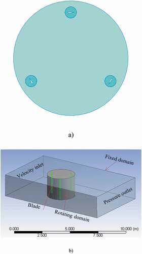
5.1. Results
1. Mesh Independence
A full 3D coupled simulation was applied to the Darrieus VAWT rotor disregarding the shaft and blade arms. The objective of the study was to compare the accuracy of turbulence models’ on VAWT performance predictions and structural performance of the blade materials under the same boundary conditions prescribed in . To study the intensity of flow reached over the turbine blades, Realizable k-ε and SST k-ω turbulence models have been used.
Table 4. Simulation Parameter.
To examine the accuracy of the computational model, the mesh sensitivity study was performed on the base model before implementing the couple simulation. The simulation domain was discretized into the rotating and stationary sub-grid, , compliant with the dynamic mesh technique. The stationary domain has the dimensions of 15 m, 3 m, and 5 m along with streamwise, vertical, and spanwise directions respectively, and illustrated in . To capture intermediate flow characteristics from the system boundary, an interface was created between the fixed and rotating sub-domain. The aerodynamic mesh settings were established with the three mesh alternatives i.e coarse, medium, and fine. The size of elements of the rotor and stationary sub-domain was 10 mm and 60 mm respectively. To have a better quality of results, the element size of each blade path was put into 50 divisions. Finally, the mesh convergence was achieved with 1,354,412 nodes and 1,270,000 elements in all conserved variables as shown in .
Figure 37. Model mesh.
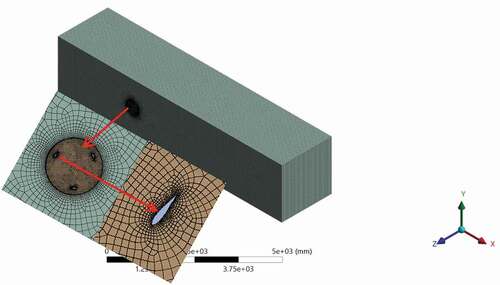
Figure 38. Model grid Independence.
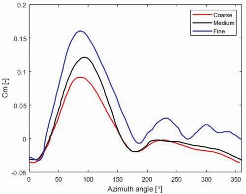
2. Model Validation
In this section, the self-starting characteristics of straight-bladed VAWT described in were investigated using FSI simulation. The simulation was carried out at realistic operating conditions reported in the table, and the air density and viscosity are set to 1.23 kg/m3 and kg/ms respectively.
Figure 39. Torque generated in FSI simulation.
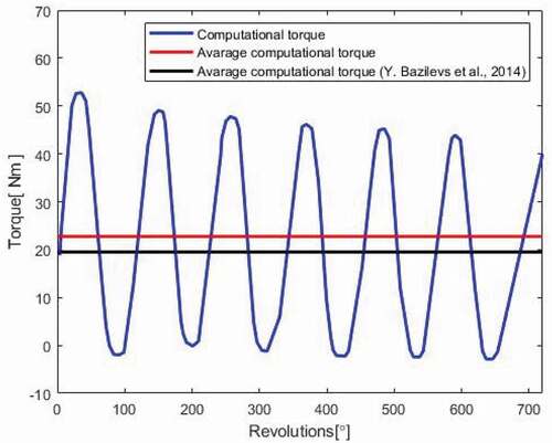
Figure 40. Aerodynamic model comparisons.
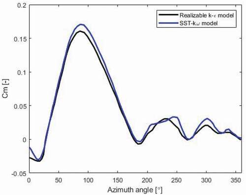
Blade structural performance
Keeping all the turbine blades fixed at both ends and under the unsteady-state coupled analysis of blade materials, the performance of aluminum alloy is very high than the synthetic composite blade (i.e. Glass epoxy). The FSI structural response was investigated by setting the structural time step 10 seconds coupled with the k-ε turbulence model and within 1 second system time interval. The maximum total deformations have occurred on the blade which was perpendicular to the inlet of boundary condition. The maximum total deflection of aluminum alloy and Epoxy_Eglass_UD is approximately 0.0642 mm and 0.691 mm respectively. These indicate that composite E-glass are more deformable and maybe failed at stormwind conditions, while aluminum alloy allows wind load resistance. Similarly, under similar conditions. Hence, the maximum strain of aluminum alloy wind turbine is 5.545x10⁻⁶[m/m] and the maximum strain of Epoxy_Eglass_UD turbine blade is 4.287 × 10⁻⁴ [m/m].
Figure 41. Total deformation contour. a) Epoxy_Eglass _UD blades b) Aluminum Alloy blades.
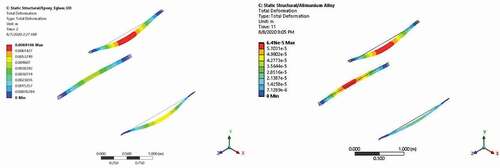
3D aerodynamic and fluid-structure instruction of H-Darrieus VAWT simulation has been carried out. The study compares the two most frequent turbulent models (i.e. k-ε and SST k-ω) used in aerodynamic studies. The result shows SST k-ω turbulence model is more reliable than the k-ε model interims of predicting the moment coefficients (Cm) of the turbine. This is because of the robustness of SST k-ω by computing near-wall and far-wall flow boundary conditions with adverse pressure gradients. In steady-state FSI analysis, the performance of the two commonly used blade materials (Epoxy_Eglass_UD and Aluminum alloy) has been compared. The result demonstrates Epoxy_Eglass_UD has larger total deformations and higher strain which may cause larger failures at stormwind conditions. Except for computational expensiveness, full-scale transient FSI simulation is a more accurate analysis to understand the action-reaction response of the fluid and the turbine structural component may have an accurate aerodynamic prediction.
So many parametric and design modifications of H-Darrieus WT with performance prediction methods are summarized in . In general, most of the authors targeted enhancing the power output of the turbine especially for enabling the turbine self-starting. Analytical, numerical, and combined methods of performance prediction are including in touch. Interim of predictions, each separate method may have their merit and demerit; combine forms such as FSI analysis provide an outstanding effort to multi-dimensional considerations in the complex aerodynamics of the turbine. Analytical models: stream tube model (STM), multiple stream tube models (MSTM), and double multiple stream tube models (DMST) and CFD models: k-ε, k-ω, and SST k-ω are the usual tools for H-Darrieus wind turbine aerodynamics study. In turn, the coupling system (FSI) becomes a mandatory and necessary tool for the high fidelity study of VAWTs. But very expensive computational costs and time consuming nature may the special drawback of this method.
Table 5. Parametric studies of H-Darrieus wind turbine Summary
6. Conclusion
Often, VAWT has a potential advantage such as omnidirectional and it can be installed anywhere if desired wind resource is available. This helps to reduce the turbine investment cost and a better energy alternative for the sites away from grid-connected electricity i.e rural areas, schools, telecommunications, military comps, health centers, research centers, etc. However, in the real fact, VAWT is not largemouth applicable in grid-connected power generation, the machine is not start-up unless an auxiliary device is supplemented to the system. The main reason behind it is that the aerodynamic nature of VAWT is too complex and affected by different parameters. With a comprehensive understanding of both structural and aerodynamics investigations, the authors give deep insight on the performance enhancement options such as using efficient airfoils, VP-blade design, optimizing the blade shape, employing flow augmentation device, allowing control methods, hybrid with other types of turbine, etc. Similarly, the influence of blade materials regarding environmental and the turbine performance aspect was also reviewed. Furthermore, the accuracy of conventional and advanced computational methods has been devoted to exploring concerning to the gross efficiency enhancement and technical means of self-startup opportunities. For example, analytical methods (BEM, MSTM, DMST), CFD (k-ε, k-ω, SST kω, LES), and advanced computational methods (FSI and AI) have been reviewed. Additionally, an FSI simulation was done on 2 KW NREL baseline VAWT to compare the structural performance of the two commonly used wind turbine blade materials (glass fiber and aluminum alloy) and the accuracy of the two turbulence models (k-ε and SST kω). These all attempts grasp multi-perspective overviews on the aerodynamics of VAWT performance enhancement. Finally, the authors are pointed out the following few critical research gaps and concepts that may shed light for future researchers
Even though several investigations have been done for H-Darrieus VAWT performance enhance, its self-starting is one of the most critical issues which limit the turbine applications. Because several studies are based on numerical predictions which may have less accuracy and wind tunnel and field test experimental validations are compulsory.
H-Darrieus VAWT is only limited to small-scale applications; however, the turbine has promising opportunities which are mentioned in this study to enable stand-alone and grid-connected electricity generation.
Studies show variable pitch (VP) blade designs are better than fixed pitch (FP) once however the details of pitch control methods and the significant elevation of performance enhancements are not quantified.
Leading-edge serration of the blade is considered as one of the performance enhancement alternatives in this investigation. However, some contradicting ideas are observed between different researchers at the same objectives.
High fidelity simulation may be difficult or even impossible using CFD methods such as FSI and LES while very expensive computational cost and time. Therefore advanced methods such as AI schemes are promising computational methods in terms of computational cost, accuracy, and stability.
AI-based aeroelastic analysis of wind turbine and system control concepts is very essential as mentioned earlier. However, there is a lack of AI-based research in the aerodynamics of H-Darrieus VAWT that may robust tool concerning turbine blade optimization, aerodynamic performance predictions, and system control.
The structural performance of any aerodynamic device depends on the physical and mechanical properties of the components. Physically most wind turbine blades are exposed to several adverse environmental conditions. However in fact due to corrosion of the synthetic blade (blades made from metals) cause catastrophic structural failure.
Since most recycling technologies are not yet commercialized, traditional end-of-life disposal methods i.e incinerated and landfills of synthetic composite blades yields high environmental depletion
Even if, research efforts are emerged with shifting synthetic turbine blade material with biodegradable fiber-based composites, high moisture absorption characteristics minimize the turbine blade standard physical requirements. This may a sophisticated method of fiber physical modification, composite manufacturing, and blade manufacturing method.
The aeroelastic and morphing characteristics of natural reinforced composite (NRFC) blades in H-Darrieus VAWT with VP-configuration are not investigated.
Nomenclatures
AoA Angle of attack
AR Aspect ratio
BC Before Christ
BEM Blade element momentum
CFD Computational fluid dynamics
DES Detached Eddy Simulation
DC Direct current
DMST Double multiple stream tube
FEM Finite element method
FP Fixed pitch
FRC Fiber-reinforced composite
FSI Fluid-structure interaction
GPA Giga Pascal
GRF Glass-reinforced fiber
GW Giga watt
HAWT Horizontal axis wind turbine
KN Kilo newton
LES Large Eddy Simulation
MST Multiple stream tube
MW Megawatt
NREL National renewable energy laboratory
NRFC Natural reinforced fiber composite
NS Navier Stoke
SNL Sandia National Laboratories
SST Shear stress transport
ST Stream tube
TSR Tip speed ratio
URANS Unsteady Reynolds averaged Navier Stoke
VAWT Vertical axis wind turbine
VP Variable pitch
WT Wind turbine
Symbols
Cm Moment coefficient
Cp Power coefficient
CT Instantaneous torque coefficient
cn Normal force coefficient
ct Tangential force coefficient
α Angle of attack
β Pitch angle
λ Tip speed ratio
φ Incident angle
θ Azimuth angle
σ Rotor solidity
a Upstream induction factor
a’ Downstream induction factor
2D Two-dimensional
3D Three-dimensional
Disclosure statement
No potential conflict of interest was reported by the author(s).
References
- Abbott, I. H., and A. E. Von Doenhoff. 1959. Theory of wing sections: Including a summary of airfoil data. Courier Corporation. 978-0486605869.
- Abdalrahman, G., W. Melek, and F.-S. Lien. 2017. Pitch angle control for a small-scale Darrieus vertical axis wind turbine with straight blades (H-Type VAWT). Renewable Energy 114:1353–62. doi:10.1016/j.renene.2017.07.068.
- Abdalrwaf, Wael. 2017. Stresses and frequency shifts in fully extended and folded wind turbine blades . Fort Collins, Colorado: Colorado State University. [Accessed10 December, 2021]. https://mountainscholar.org/bitstream/handle/10217/185728/Abdalrwaf_colostate_0053N_14548.pdf?sequence=1
- Afzali, F., O. Kapucu, and B. F. Feeny. 2016. “Vibration analysis of vertical-axis wind-turbine blades,” in ASME 2016 International Design Engineering Technical Conferences and Computers and Information in Engineering Conference, August 21–24, 2016, Charlotte, North Carolina, USA. USA: American Society of Mechanical Engineers Digital Collection. https://doi.org/10.1115/DETC2016-60374
- Ageze, M. B., Y. Hu, and A. H. Wu. 2017a. Wind Turbine Aeroelastic Modeling: Basics and Cutting Edge Trends. International Journal of Aerospace Engineering 2017 (5263897):15.
- Ageze, M. B., Y. Hu, and H. Wu. 2017b. Wind turbine aeroelastic modeling:Basics and cutting edge trends. International Journal of Aerospace Engineering 2017:1–15. doi:10.1155/2017/5263897.
- Ahmed, M. F., and A. F. A. Gawad. 2016. “Utilization of wind energy in green buildings,” In 12th International Conference of Fluid Dynamics, Le Méridien Pyramids Hotel pp. 19–20. Cairo, Egypt.
- Almohammadi, K., D. Ingham, L. Ma, and M. Pourkashan. 2013. Computational fluid dynamics (CFD) mesh independency techniques for a straight blade vertical axis wind turbine. Energy 58:483–93. doi:10.1016/j.energy.2013.06.012.
- Almohammadi, K., D. Ingham, L. Ma, and M. Pourkashanian. 2015. Modeling dynamic stall of a straight blade vertical axis wind turbine. Journal of Fluids and Structures 57:144–58. doi:10.1016/j.jfluidstructs.2015.06.003.
- Arab, A., M. Javadi, M. Anbarsooz, and M. Moghiman. 2017. A numerical study on the aerodynamic performance and the self-starting characteristics of a Darrieus wind turbine considering its moment of inertia. Renewable Energy 107:298–311. doi:10.1016/j.renene.2017.02.013.
- Ashby, M. F. 2008. The CES EduPack database of natural and man-made materials. In Granta Material Inspiration, 1st ed., Bioengineering. UK: Cambridge University and Granta Design. https://www.grantadesign.com/download/pdf/biomaterials.pdf
- Ayati, A. A., K. Steiros, M. A. Miller, S. Duvvuri, and M. Hultmark. 2019. A double-multiple streamtube model for vertical axis wind turbines of arbitrary rotor loading. Wind Energy Science 4 (4):653–62. doi:10.5194/wes-4-653-2019.
- Balduzzi, F., J. Drofelnik, A. Bianchini, G. Ferrara, L. Ferrari, and M. S. Campobasso. 2017. Darrieus wind turbine blade unsteady aerodynamics: A three-dimensional Navier-Stokes CFD assessment. Energy 128:550–63. doi:10.1016/j.energy.2017.04.017.
- Batista, N., R. Melício, V. M. Mendes, J. Figueiredo, and A. Reis. 2013. Darrieus wind turbine performance prediction: Computational modeling,” In Technological Innovation for the Internet of Things. DoCEIS 2013. IFIP Advances in Information and Communication Technology, vol. 394, pp. 382–391. Berlin Heidelberg: Springer Berlin Heidelberg.
- Bazilevs, Y., A. Korobenko, X. Deng, and J. Yan. 2015. Novel structural modeling and mesh moving techniques for advanced fluid–structure interaction simulation of wind turbines. International Journal for Numerical Methods in Engineering 102 (3–4):766–83. doi:10.1002/nme.4738.
- Bazilevs, Y., A. Korobenko, X. Deng, J. Yan, M. Kinzel, and J. Dabiri. 2014. Fluid–structure interaction modeling of vertical-axis wind turbines. Journal of Applied Mechanics 81 (8). doi:10.1115/1.4027466.
- Bazilevs, Y., M. C. Hsu, J. Kiendl, R. Wüchner, and K. U. Bletzinger. 2011. 3D simulation of wind turbine rotors at full scale. Part II: Fluid–structure interaction modeling with composite blades. International Journal for Numerical Methods in Fluids 65 (1‐3):236–53. doi:10.1002/fld.2454.
- Beardmore, P., and C. Johnson. 1986. The potential for composites in structural automotive applications. Composites Science and Technology 26 (4):251–81. doi:10.1016/0266-3538(86)90002-3.
- Bedon, G., M. R. Castelli, and E. Benini. 2013. Optimization of a Darrieus vertical-axis wind turbine using blade element–momentum theory and evolutionary algorithm. Renewable Energy 59:184–92. doi:10.1016/j.renene.2013.03.023.
- Beri, H., and Y. Yao. 2011. Double multiple streamtube model and numerical analysis of vertical axis wind turbine. Energy and Power Engineering 3 (3):262. doi:10.4236/epe.2011.33033.
- Bhutta, M. M. A., N. Hayat, A. U. Farooq, Z. Ali, S. R. Jamil, and Z. Hussain. 2012. Vertical axis wind turbine–A review of various configurations and design techniques. Renewable and Sustainable Energy Reviews 16 (4):1926–39. doi:10.1016/j.rser.2011.12.004.
- Bhuvaneswari, C., and R. Rajeswari. 2013. Study analysis of hybrid power plant (wind-solar)-vertical axis wind turbine-giromill darrieus type with evacuated tube collectors. International Journal of Emerging Trends in Electrical and Electronics1 (1):80–83.
- Bhuyan, S., and A. Biswas. 2014. Investigations on self-starting and performance characteristics of simple H and hybrid H-Savonius vertical axis wind rotors. Energy Conversion and Management 87:859–67. doi:10.1016/j.enconman.2014.07.056.
- Bianchini, A., F. Balduzzi, G. Ferrara, and L. Ferrari. 2016. Virtual incidence effect on rotating airfoils in Darrieus wind turbines. Energy Conversion and Management 111:329–38. doi:10.1016/j.enconman.2015.12.056.
- Binici, H., O. Aksogan, and C. Demirhan. 2016. Mechanical, thermal and acoustical characterizations of an insulation composite made of bio-based materials. Sustainable Cities and Society 20:17–26. doi:10.1016/j.scs.2015.09.004.
- Biswas, A., and R. Gupta. 2014. Unsteady aerodynamics of a twist bladed H-Darrieus rotor in low Reynolds number flow. Journal of Renewable and Sustainable Energy 6 (3):033108. doi:10.1063/1.4878995.
- Blanchard, J. M. F. A., and A. J. Sobey. 2019. Comparative design of E-glass and flax structures based on reliability.Composite Structures 225 , 111037. https://doi.org/10.1016/j.compstruct.2019.111037
- Boria, S., C. Santulli, E. Raponi, F. Sarasini, and J. Tirillò. 2019. Evaluation of a new green composite solution for wind turbine blades. Multiscale and Multidisciplinary Modeling, Experiments and Design 2 (2):141–50. doi:10.1007/s41939-019-00043-4.
- Bose, B. K. 2017. Artificial intelligence techniques in smart grid and renewable energy systems—Some example applications. Proceedings of the IEEE 105 (11):2262–73. doi:10.1109/JPROC.2017.2756596.
- Boumhaout, M., L. Boukhattem, H. Hamdi, B. Benhamou, and F. A. Nouh. 2017. Thermomechanical characterization of a bio-composite building material: Mortar reinforced with date palm fibers mesh. Construction and Building Materials 135:241–50. doi:10.1016/j.conbuildmat.2016.12.217.
- Brahimi, T. 2019. Using artificial intelligence to predict wind speed for energy application in Saudi Arabia. Energies 12 (24):4669. doi:10.3390/en12244669.
- Bravo, A., L. Toubal, D. Koffi, and F. Erchiqui. 2018. Gear fatigue life and thermomechanical behavior of novel green and bio-composite materials VS high-performance thermoplastics. Polymer Testing 66:403–14. doi:10.1016/j.polymertesting.2016.12.031.
- Brochier, G., P. Fraunie, C. Beguier, and I. Paraschivoiu. 1986. Water channel experiments of dynamic stall on Darrieus wind turbine blades. Journal of Propulsion and Power 2 (5):445–49. doi:10.2514/3.22927.
- Brown, K., and R. Brooks. 2010. Design and analysis of vertical axis thermoplastic composite wind turbine blade. Plastics, Rubber and Composites 39 (3–5):111–21. doi:10.1179/174328910X12647080902655.
- Buchner, A.-J., J. Soria, D. Honnery, and A. J. Smits. 2018. Dynamic stall in vertical axis wind turbines: Scaling and topological considerations. Journal of Fluid Mechanics 841:746–66. doi:10.1017/jfm.2018.112.
- Buturache, A.-N., and S. Stancu. 2021. Wind energy prediction using machine learning. Low Carbon Economy 12 (1):1. doi:10.4236/lce.2021.121001.
- Cadu, T., M. Berges, O. Sicot, V. Person, B. Piezel, L. Van Schoors, V. Placet, S. Corn, R. Léger, L Divet, et al. 2018. What are the key parameters to produce a high-grade bio-based composite? Application to flax/epoxy UD laminates produced by thermocompression. Composites Part B: Engineering 150:36–46. doi:10.1016/j.compositesb.2018.04.059.
- Camporeale, S. M., and V. Magi. 2000. Streamtube model for analysis of vertical axis variable pitch turbine for marine currents energy conversion. Energy Conversion and Management 41 (16):1811–27. doi:10.1016/S0196-8904(99)00183-1.
- Cao, H., X. Wu, H. Ye, S. Hu, L. Lu, and J. Peng. 2018. “Optimization research on lift-type vertical axis wind turbine airfoil by CFD,” In Journal of Physics: Conference Series, 2018. 1064, vol. 1, p. 012072: IOP Publishing. https://iopscience.iop.org/article/10.1088/1742-6596/1064/1/012072
- Carr, L. W. 1988. Progress in analysis and prediction of dynamic stall. Journal of Aircraft 25 (1):6–17. doi:10.2514/3.45534.
- Casás, V. D., F. L. Pena, R. J. Duro, and A. Lamas, “Automatic aerodynamic design of a wind turbine through evolutionary techniques,” in 2005 IEEE Intelligent Data Acquisition and Advanced Computing Systems: Technology and Applications, 2005, pp. 454–59IEEE.https://ieeexplore.ieee.org/document/4062174
- Castelli, M. R., A. Dal Monte, M. Quaresimin, and E. Benini. 2013. Numerical evaluation of aerodynamic and inertial contributions to Darrieus wind turbine blade deformation. Renewable Energy 51:101–12. doi:10.1016/j.renene.2012.07.025.
- Castelli, M. R., A. Englaro, and E. Benini. 2011. The Darrieus wind turbine: Proposal for a new performance prediction model based on CFD. Energy 36 (8):4919–34. doi:10.1016/j.energy.2011.05.036.
- Castelli, M. R., S. De Betta, and E. Benini. 2012. Effect of blade number on a straight-bladed vertical-axis Darrieus wind turbine. World Academy of Science, Engineering and Technology 61:305–11.
- Chandrasekhar, K., N. Stevanovic, E. J. Cross, N. Dervilis, and K. Worden. 2021. Damage detection in operational wind turbine blades using a new approach based on machine learning. Renewable Energy 168:1249–64. doi:10.1016/j.renene.2020.12.119.
- Chatterjee, R., “Fundamental concepts of artificial intelligence and its applications,” 2020.
- Chegdani, F., M. El Mansori, S. Mezghani, and A. Montagne. 2017. Scale effect on tribo-mechanical behavior of vegetal fibers in reinforced bio-composite materials. Composites Science and Technology 150:87–94. doi:10.1016/j.compscitech.2017.07.012.
- Chehouri, A., R. Younes, A. Ilinca, and J. Perron. 2016. Wind turbine design: Multi‐objective optimization. In Wind turbines. design, control and applications, ed. A. G. Aissaoui, and A. Tahour, IntechOpen . 121–48. https://www.intechopen.com/chapters/50998
- Chen, J., L. Chen, H. Xu, H. Yang, C. Ye, and D. Liu. 2016. Performance improvement of a vertical axis wind turbine by comprehensive assessment of an airfoil family. Energy 114:318–31. doi:10.1016/j.energy.2016.08.005.
- Chen, X., M. A. Eder, A. Shihavuddin, and D. Zheng. 2021. A human-cyber-physical system toward intelligent wind turbine operation and maintenance. Sustainability 13 (2):561. doi:10.3390/su13020561.
- Chen, Y., and Y. Lian. 2015. Numerical investigation of vortex dynamics in an H-rotor vertical axis wind turbine. Engineering Applications of Computational Fluid Mechanics 9 (1):21–32. doi:10.1080/19942060.2015.1004790.
- Chougule, P., and S. Nielsen, “Overview and design of self-acting pitch control mechanism for vertical axis wind turbine using multi body simulation approach,” In Journal of Physics: Conference Series, 2014, Copenhagen, Denmark, 2014, vol. 524, no. 1, p. 012055. IOP Publishing. https://iopscience.iop.org/article/10.1088/1742-6596/524/1/012055
- Clifton, A., L. Kilcher, J. Lundquist, and P. Fleming. 2013. Using machine learning to predict wind turbine power output. Environmental Research Letters 8 (2):024009. doi:10.1088/1748-9326/8/2/024009.
- Dabachi, M. A., A. Rahmouni, and O. Bouksour. 2020. Design and aerodynamic performance of new floating H-darrieus vertical Axis wind turbines. Materials Today: Proceedings 30:899–904.
- Danao, L. A., N. Qin, and R. Howell. 2012. A numerical study of blade thickness and camber effects on vertical axis wind turbines,” Proceedings of the Institution of Mechanical Engineers, Part A: Journal of Power and Energy , vol. 226, no. 7, pp. 867–81. doi:10.1177/0957650912454403.
- Davies, P., and P. Chauchot. 1999. Composites for marine applications. In Mechanics of composite materials and structures, 249–60. Springer, Dordrecht. https://doi.org/10.1007/978-94-011-4489-6_12
- Davoodi, M., S. Sapuan, D. Ahmad, A. Aidy, A. Khalina, and M. Jonoobi. 2011. Concept selection of car bumper beam with developed hybrid bio-composite material. Materials & Design 32 (10):4857–65. doi:10.1016/j.matdes.2011.06.011.
- de Santoli, L., A. Albo, D. A. Garcia, D. Bruschi, and F. Cumo. 2014. A preliminary energy and environmental assessment of a micro wind turbine prototype in natural protected areas. Sustainable Energy Technologies and Assessments 8:42–56. doi:10.1016/j.seta.2014.07.002.
- Delafin, P.-L., T. Nishino, A. Kolios, and L. Wang. 2017. Comparison of low-order aerodynamic models and RANS CFD for full scale 3D vertical axis wind turbines. Renewable Energy 109:564–75. doi:10.1016/j.renene.2017.03.065.
- Deng, W., Y. Yu, L. Liu, Y. Guo, and H. Zhao. 2020. Research on the dynamical responses of H-type floating VAWT considering the rigid-flexible coupling effect. Journal of Sound and Vibration 469:115162. doi:10.1016/j.jsv.2019.115162.
- Douak, M., Z. Aouachria, R. Rabehi, and N. Allam. 2018. Wind energy systems: Analysis of the self-starting physics of vertical axis wind turbine. Renewable and Sustainable Energy Reviews 81:1602–10. doi:10.1016/j.rser.2017.05.238.
- Duflou, J. R., Y. Deng, K. Van Acker, and W. Dewulf. 2012. Do fiber-reinforced polymer composites provide environmentally benign alternatives? A life-cycle-assessment-based study. Mrs Bulletin 37 (4):374–82. doi:10.1557/mrs.2012.33.
- Dwiyantoro, B. A., and V. Suphandani. 2017. The system design and performance test of hybrid vertical axis wind turbine. In AIP Conference Proceedings. American Institute of Physics . doi:10.1063/1.4981171.
- Dyachuk, E., and A. Goude. 2015. Numerical validation of a vortex model against experimental data on a straight-bladed vertical axis wind turbine. Energies 8 (10):11800–20. doi:10.3390/en81011800.
- Eker, B., A. Akdogan, and A. Vardar. 2006. Using of composite material in wind turbine blades. Journal of Applied Sciences 6 (14):2917–21. doi:10.3923/jas.2006.2917.2921.
- El Baz, A., A. Rafaey, M. Y. Mohammed, and W. Youssef. 2013. “Computational modelling of H-type Darrieus vertical axis wind turbine with multi element airfoil blades,” In Proceedings of ICFD11, Eleventh International Conference of Fluid Dynamics. Alexandria, Egypt.
- Elalaoui, R. 2019. Investigation and analysis of static and dynamic behaviour of a new natural composite material of a wind turbine blade using the finite element method. International Journal of Renewable Energy Research (IJRER) 9 (1):363–73.
- Elkhoury, M., T. Kiwata, and E. Aoun. 2015. Experimental and numerical investigation of a three-dimensional vertical-axis wind turbine with variable-pitch. Journal of Wind Engineering and Industrial Aerodynamics 139:111–23. doi:10.1016/j.jweia.2015.01.004.
- Elsakka, M. M., D. B. Ingham, L. Ma, and M. Pourkashanian. 2019. CFD analysis of the angle of attack for a vertical axis wind turbine blade. Energy Conversion and Management 182:154–65. doi:10.1016/j.enconman.2018.12.054.
- Eriksson, J. 2020. Machine Learning for Predictive Maintenance on Wind Turbines : Using SCADA Data and the Apache Hadoop Ecosystem. Linköping University. http://urn.kb.se/resolve?urn=urn:nbn:se:liu:diva-164892
- Feng, F., C. Qu, S. Zhao, Y. Bai, W. Guo, and Y. Li. 2018. Static mechanical properties and modal analysis of a kind of lift-drag combined-type vertical axis wind turbine. International Journal of Rotating Machinery 2018:1–13. doi:10.1155/2018/1840914.
- Fereidooni, A., F. Nitzsche, and E. Matida . 2014. Aeroelastic study of a vertical axis wind turbine with troposkien shape,” in 32nd ASME Wind Energy Symposium 2014. National Harbor, Maryland, 2014. https://doi.org/10.2514/6.2014-0716
- Ferrari, G. M. 2012. Development of an Aeroelastic Simulation for the Analysis of Vertical-Axis Wind Turbines. University of Auckland.
- Ferreira, C. S., H. A. Madsen, M. Barone, B. Roscher, P. Deglaire, and I. Arduin. 2014. Comparison of aerodynamic models for vertical axis wind turbines. In Journal of Physics: Conference Series, vol. 524, 012125, Copenhagen, Denmark: 1IOP Publishing. doi:10.1088/1742-6596/524/1/012125.
- Ferreira, C. S., H. Bijl, G. Van Bussel, and G Van Kuik. 2007. Simulating dynamic stall in a 2D VAWT: Modeling strategy, verification and validation with particle image velocimetry data. Journal of Physics: Conference Series 751,012023 IOP Publishing
- Fleming, P., and S. Probert. 1984. The evolution of wind-turbines: An historical review. Applied Energy 18 (3):163–77. doi:10.1016/0306-2619(84)90007-2.
- Florentin, Y., D. Pearlmutter, B. Givoni, and E. Gal. 2017. A life-cycle energy and carbon analysis of hemp-lime bio-composite building materials. Energy and Buildings 156:293–305. doi:10.1016/j.enbuild.2017.09.097.
- Friedmann, P. P. 1976. Aeroelastic modeling of large wind turbines. Journal of the American Helicopter Society 21 (4):17–27. doi:10.4050/JAHS.21.17.
- G. H., Airplane propellers. 1963. Durand WF Ed. Aerodynamic theory. New YorK: Dover Publications;.
- Gao, L., H. Zhang, Y. Liu, and S. Han. 2015. Effects of vortex generators on a blunt trailing-edge airfoil for wind turbines. Renewable Energy 76:303–11. doi:10.1016/j.renene.2014.11.043.
- Ghasemian, M., Z. N. Ashrafi, and A. Sedaghat. 2017. A review on computational fluid dynamic simulation techniques for Darrieus vertical axis wind turbines. Energy Conversion and Management 149:87–100. doi:10.1016/j.enconman.2017.07.016.
- Griffith, D. T. 2018. Design studies for deep-water floating offshore vertical axis wind turbines . Albuquerque, NM (United States): Sandia National Lab.(SNL-NM). https://doi.org/10.2172/1459118
- Guo, J., P. Zeng, and L. Lei. 2019. Performance of a straight-bladed vertical axis wind turbine with inclined pitch axes by wind tunnel experiments. Energy 174:553–61. doi:10.1016/j.energy.2019.02.177.
- Gupta, R., and A. Biswas. 2010. Computational fluid dynamics analysis of a twisted three-bladed H-Darrieus rotor. Journal of Renewable and Sustainable Energy 2 (4):043111. doi:10.1063/1.3483487.
- Haggui, M., A. El Mahi, Z. Jendli, A. Akrout, and M. Haddar. 2019. Static and fatigue characterization of flax fiber reinforced thermoplastic composites by acoustic emission. Applied Acoustics 147:100–10. doi:10.1016/j.apacoust.2018.03.011.
- Hakeem Saleh, A. F. A. 2017. Modal analysis of vertical-axis darrieus wind turbine blade with a troposkein shape. Michigan State University. h ttps://d oi.o rg/1 0.25335/M5C00G
- Hallonet, A., E. Ferrier, L. Michel, and B. Benmokrane. 2019. Durability and tensile characterization of wet lay-up flax/epoxy composites used for external strengthening of RC structures. Construction and Building Materials 205:679–98. doi:10.1016/j.conbuildmat.2019.02.040.
- Hamdan, A., and F. Mustapha. 2017. The macro fiber composite (MFC) bonded effect analysis on the micro energy harvester performance and structural health monitoring system of woven kenaf turbine blade for vertical axis wind turbine application. Innovation in Smart Materials and Structural Health Monitoring for Composite Applications 13:141.
- Hamdan, A., F. Mustapha, K. Ahmad, and A. M. Rafie. 2014. A review on the micro energy harvester in Structural Health Monitoring (SHM) of biocomposite material for Vertical Axis Wind Turbine (VAWT) system: A Malaysia perspective. Renewable and Sustainable Energy Reviews 35:23–30. doi:10.1016/j.rser.2014.03.050.
- Hameed, M. S., S. K. Afaq, and F. Shahid. 2015. Finite element analysis of a composite VAWT blade. Ocean Engineering 109:669–76. doi:10.1016/j.oceaneng.2015.09.032.
- Hand, B., G. Kelly, and A. Cashman. 2021. Aerodynamic design and performance parameters of a lift-type vertical axis wind turbine: A comprehensive review. Renewable and Sustainable Energy Reviews 139:110699. doi:10.1016/j.rser.2020.110699.
- Hansen, M. O. L., J. N. Sørensen, S. Voutsinas, N. Sørensen, and H. A. Madsen. June 2006. State of the art in wind turbine aerodynamics and aeroelasticitys. Progress in Aerospace Science 42(4):285–330. doi:10.1016/j.paerosci.2006.10.002.
- Hara, Y., K. Hara, and T. Hayashi. 2012. Moment of inertia dependence of vertical axis wind turbines in pulsating winds. International Journal of Rotating Machinery 2012:1–12. doi:10.1155/2012/910940.
- Hashem, I., and M. Mohamed. 2018. Aerodynamic performance enhancements of H-rotor Darrieus wind turbine. Energy 142:531–45. doi:10.1016/j.energy.2017.10.036.
- Hilewit, D., E. Matida, A. Fereidooni, H. Abo El Ella, and F. Nitzsche. 2019. Numerical investigations of a novel vertical axis wind turbine using Blade Element Theory‐Vortex Filament Method (BET‐VFM). Energy science & engineering. Vol. 76,2498–2509
- Hirsch, I. H., and A. Mandal. 1987. A Cascade Theory for the Aerodynamic Performance of Darrieus Wind Turbines. Wind Engineering 11 (3): 164–175. http://www.jstor.org/stable/43749306
- Howard, B. 2017. Iran’s centuries-old windmills may soon stop turning. National Geographic .
- Howell, R., N. Qin, J. Edwards, and N. Durrani. 2010. Wind tunnel and numerical study of a small vertical axis wind turbine. Renewable Energy 35 (2):412–22. doi:10.1016/j.renene.2009.07.025.
- Hwang, I. S., S. Y. Min, I. O. Jeong, Y. H. Lee, and S. J. Kim. 2006. Efficiency improvement of a new vertical axis wind turbine by individual active control of blade motion. In Smart structures and materials 2006: Smart structures and integrated systems, Vol. 6173, San Diego, California, United States: International Society for Optics and Photonics.https://doi.org/10.1117/12.658935
- Immarigeon, J., R. Holt, A. Koul, L. Zhao, W. Wallace, and J. Beddoes. 1995. Lightweight materials for aircraft applications. Materials Characterization 35 (1):41–67. doi:10.1016/1044-5803(95)00066-6.
- IRENA. 2019. Future of wind: Deployment, investment, technology, grid integration and socio-economic aspects(A global energy transformation paper). Abu Dhabi: International Renewable Energy Agency.
- Islam, M., D. S.-K. Ting, and A. Fartaj. 2008. Aerodynamic models for Darrieus-type straight-bladed vertical axis wind turbines. Renewable and Sustainable Energy Reviews 12 (4):1087–109. doi:10.1016/j.rser.2006.10.023.
- Jahanmiri, M., A. Shooshtaryrezvany, and M. Nirooei. 2016. A computational study of the effect of blade thickness on performance of vertical axis wind turbine. IOSR Journal of Mechanical and Civil Engineering 13 (5):57–65. doi:10.9790/1684-1305025765.
- Jayabalan, J., D. Yildirim, D. Kim, and P. Samui. 2017. Design optimization of a wind turbine using artificial intelligence. In Mathematical concepts and applications in mechanical engineering and mechatronics, 38–66. IGI Global.
- Jeannin, Thomas., Berges, Michaël., Gabrion, Xavier., Léger, Romain., Person, Véronique., Corn, Stéphane., Piezel, Benoit., Ienny, Patrick., Fontaine, Stéphane., Placet, Vincent.2019. Influence of hydrothermal ageing on the fatigue behaviour of a unidirectional flax-epoxy laminate. In Composites Part B: Engineering 174. d oi.o rg/1 0.1016/j.c ompositesb.2019.107056
- Jiang, Y., C. He, P. Zhao, and T. Sun. 2020. Investigation of blade tip shape for improving VAWT performance. Journal of Marine Science and Engineering 8 (3):225. doi:10.3390/jmse8030225.
- Kalagi, G. R., R. Patil, and N. Nayak. 2018. Experimental study on mechanical properties of natural fiber reinforced polymer composite materials for wind turbine blades. Materials Today: Proceedings 5 (1):2588–96.
- Kalkanis, K., C. Psomopoulos, S. Kaminaris, G. Ioannidis, and P. Pachos. 2019. Wind turbine blade composite materials-End of life treatment methods. Energy Procedia 157:1136–43. doi:10.1016/j.egypro.2018.11.281.
- Khodadadi, Amin, Gholamhossein Liaghat, Ahmad Reza Bahramian, Hamed Ahmadi, Yavar Anani, Samaneh Asemani, Omid Razmkhah, . 2019. High velocity impact behavior of Kevlar/rubber and Kevlar/epoxy composites: A comparative study. Composite Structures 216:159–167. doi:10.1016/j.compstruct.2019.02.080.
- Kim, D., and M. Gharib. 2013. Efficiency improvement of straight-bladed vertical-axis wind turbines with an upstream deflector. Journal of Wind Engineering and Industrial Aerodynamics 115:48–52. doi:10.1016/j.jweia.2013.01.009.
- Kim, D., and M. Gharib. 2014. Unsteady loading of a vertical-axis turbine in the interaction with an upstream deflector. Experiments in Fluids 55 (1):1658. doi:10.1007/s00348-013-1658-4.
- Kirke, B., and L. Lazauskas. 2011. Limitations of fixed pitch Darrieus hydrokinetic turbines and the challenge of variable pitch. Renewable Energy 36 (3):893–97. doi:10.1016/j.renene.2010.08.027.
- Kiwata, T., T. Yamada, T. Kita, S. Takata, N. Komatsu, and S. Kimura. 2010. Performance of a vertical axis wind turbine with variable-pitch straight blades utilizing a linkage mechanism. Journal of Environment and Engineering 5 (1):213–25. doi:10.1299/jee.5.213.
- Kong, C., J. Bang, and Y. Sugiyama. 2005. Structural investigation of composite wind turbine blade considering various load cases and fatigue life. Energy 30 (11–12):2101–14. doi:10.1016/j.energy.2004.08.016.
- Kumar, P. M., S. R. Rashmitha, N. Srikanth, and T.-C. Lim. 2017a. Wind tunnel validation of double multiple streamtube model for vertical axis wind turbine. Smart Grid and Renewable Energy 8 (12):412–24.
- Kumar, P. M., S. R. Rashmitha, N. Srikanth, and T.-C. Lim. 2017b. Wind tunnel validation of double multiple streamtube model for vertical axis wind turbine. Smart Grid and Renewable Energy 8 (12):412. doi:10.4236/sgre.2017.812027.
- Kusnick, J., and D. Adams. 2012. Vertical axis wind turbine operational modal analysis in sheared wind flow. In Topics in experimental dynamics substructuring and wind turbine dynamics, Vol. 2, 333–344. Springer New York. doi:10.1007/978-1-4614-2422-2_29.
- Lanting, Z. 2012. Research on structural lay-up optimum design of composite wind turbine blade. Energy Procedia 14:637–42. doi:10.1016/j.egypro.2011.12.988.
- Lanzafame, R., S. Mauro, and M. Messina. 2014. 2D CFD modeling of H-Darrieus wind turbines using a transition turbulence model. Energy Procedia 45:131–40. doi:10.1016/j.egypro.2014.01.015.
- Latoufis, K., V. Riziotis, S. Voutsinas, and N. Hatziargyriou, “Effects of leading edge erosion on the power performance and acoustic noise emissions of locally manufactured small wind turbine blades,” in Journal of Physics: Conference Series, 2019, vol. 1222, no. 1. IOP Publishing. doi:10.1088/1742-6596/1222/1/012010.
- Lau, K.-T., P.-Y. Hung, M.-H. Zhu, and D. Hui. 2018. Properties of natural fibre composites for structural engineering applications. Composites Part B: Engineering 136:222–33. doi:10.1016/j.compositesb.2017.10.038.
- Lee, Y.-J., Y.-T. Jhan, and C.-H. Chung. 2012. Fluid–structure interaction of FRP wind turbine blades under aerodynamic effect. Composites Part B: Engineering 43 (5):2180–91. doi:10.1016/j.compositesb.2012.02.026.
- Li, C., Y. Xiao, Y.-L. Xu, Y.-X. Peng, G. Hu, and S. Zhu. 2018. Optimization of blade pitch in H-rotor vertical axis wind turbines through computational fluid dynamics simulations. Applied Energy 212:1107–25. doi:10.1016/j.apenergy.2017.12.035.
- Li, Q. A., T. Maeda, Y. Kamada, Y. Hiromori, A. Nakai, and T. Kasuya. 2017. Study on stall behavior of a straight-bladed vertical axis wind turbine with numerical and experimental investigations. Journal of Wind Engineering and Industrial Aerodynamics 164:1–12. doi:10.1016/j.jweia.2017.02.005.
- Li, Q. A, Maeda, Takao, Kamada, Yasunari, Shimizu, Kento, Ogasawara, Tatsuhiko, Nakai, Alisa, Kasuya, Takuji. 2017. Effect of rotor aspect ratio and solidity on a straight-bladed vertical axis wind turbine in three-dimensional analysis by the panel method. Energy 121:1–9. doi:10.1016/j.energy.2016.12.112.
- Li, Qing'an, Maeda, Takao, Kamada, Yasunari, Shimizu, Kento, Ogasawara, Tatsuhiko, Nakai, Alisa, Kasuya, Takuji. 2014. Aerodynamic models and wind tunnel for straight-bladed vertical axis wind turbines. J. Eng 4 (6):35–44.
- Li, Qing'an, Takao Maeda, Yasunari Kamada, Junsuke Murata, Toshiaki Kawabata, Kento Shimizu, Tatsuhiko Ogasawara, Alisa Nakai, Takuji Kasuya. 2016. Wind tunnel and numerical study of a straight-bladed vertical axis wind turbine in three-dimensional analysis (Part II: For predicting flow field and performance). Energy 104:295–307. doi:10.1016/j.energy.2016.03.129.
- Li, Qing'an, Takao, Maeda, Yasunari, Kamada, Yasunari, Kamada, Junsuke, Murata, Toshiaki, Kawabata, Kento, Shimizu, Tatsuhiko, Ogasawara, Alisa, Nakai, Takuji, Kasuya. 2016. Wind tunnel and numerical study of a straight-bladed vertical axis wind turbine in three-dimensional analysis (Part I: For predicting aerodynamic loads and performance). In Energy, Vol. 106 (Elsevier). 443–452 . doi:10.1016/j.energy.2016.03.089.
- Li, Y., and S. M. Calisal. 2010. Three-dimensional effects and arm effects on modeling a vertical axis tidal current turbine. Renewable Energy 35 (10):2325–34. doi:10.1016/j.renene.2010.03.002.
- Li, Yan. 2019. Straight-bladed vertical axis wind turbines: History, performance, and applications, In Rotating machinery. Getu, Hailu: IntechOpen. doi:10.5772/intechopen.84761.
- Lin, J., Y.-L. Xu, and Y. Xia. 2019. Structural Analysis of Large-Scale Vertical Axis Wind Turbines Part II: Fatigue and Ultimate Strength Analyses. Energies 12 (13):2584. doi:10.3390/en12132584.
- Liu, K., M. Yu, and W. Zhu. 2019. Enhancing wind energy harvesting performance of vertical axis wind turbines with a new hybrid design: A fluid-structure interaction study. Renewable Energy 140:912–27. doi:10.1016/j.renene.2019.03.120.
- Liu, Y., H. Cheng, X. Kong, Q. Wang, and H. Cui. 2019. Intelligent wind turbine blade icing detection using supervisory control and data acquisition data and ensemble deep learning. Energy Science & Engineering 7 (6):2633–45. doi:10.1002/ese3.449.
- Lositaño, I. C. M., and L. A. M. Danao. 2018a. Modelling the Performance of a Vertical Axis Wind Turbine with Cambered Tubercle Leading Edge Blades. In The World Congress on Engineering, 73–86. Springer, Singapore. https://doi.org/10.1007/978-981-32-9531-5_6
- Lositaño, I. C. M., and L. A. M. Danao 2018 , “The performance of a vertical axis wind turbine with camber and tubercle leading edge as blade passive motion controls,” in Proceedings of the World Congress on Engineering July 4–6, 2018 London, U.K, 2018b, vol. II.
- Lositaño, I. C. M., and L. A. M. Danao. 2019. Steady wind performance of a 5 kW three-bladed H-rotor Darrieus Vertical Axis Wind Turbine (VAWT) with cambered tubercle leading edge (TLE) blades. Energy 175:278–91. doi:10.1016/j.energy.2019.03.033.
- Lotfi, A., H. Li, D. V. Dao, and G. Prusty. 2019. Natural fiber–reinforced composites: A review on material, manufacturing, and machinability. Journal of Thermoplastic Composite Materials. 0892705719844546. https://doi.org/10.1177/0892705719844546
- Ma, L., X. Wang, J. Zhu, and S. Kang. 2019. Dynamic stall of a vertical-axis wind turbine and its control using plasma actuation. Energies 12 (19):3738. doi:10.3390/en12193738.
- Ma, N., H. Lei, Z. Han, D. Zhou, Y. Bao, K. Zhang, L. Zhou, C Chen. 2018. Airfoil optimization to improve power performance of a high-solidity vertical axis wind turbine at a moderate tip speed ratio. Energy 150:236–52. doi:10.1016/j.energy.2018.02.115.
- MacPhee, D. W., and A. Beyene. 2016. Fluid–structure interaction analysis of a morphing vertical axis wind turbine. Journal of Fluids and Structures 60:143–59. doi:10.1016/j.jfluidstructs.2015.10.010.
- MacPhee, D., and A. Beyene. 2013. Fluid‐structure interaction of a morphing symmetrical wind turbine blade subjected to variable load. International Journal of Energy Research 37 (1):69–79. doi:10.1002/er.1925.
- Mahesh, V., S. Joladarashi, and S. M. Kulkarni. 2019. An experimental investigation on low-velocity impact response of novel jute/rubber flexible bio-composite. Composite Structures 225:111190. doi:10.1016/j.compstruct.2019.111190.
- Manwell, J. F., J. G. McGowan, and A. L. Rogers. 2010. Wind energy explained: Theory, design and application, 2nd. John Wiley & Sons. 978-0-470-01500-1.
- Marshall, J. G., and M. Imregun. 1996. A review of aeroelasticity methods with emphasis on turbomachinery applications. Journal of Fluids and Structures 10 (3):237–67. doi:10.1006/jfls.1996.0015.
- Martinez, C., F. Asare Yeboah, S. Herford, M. Brzezinski, and V. Puttagunta. 2019. Predicting wind turbine blade erosion using machine learning. SMU Data Science Review 2 (2):17.
- Mat Daud, S. Z., F. Mustapha, and Z. Adzis. 2018. Lightning strike evaluation on composite and biocomposite vertical-axis wind turbine blade using structural health monitoring approach. Journal of Intelligent Material Systems and Structures 29 (17):3444–55. doi:10.1177/1045389X17754259.
- Mazarbhuiya, H. M. S. M., A. Biswas, and K. K. Sharma. 2020a. Low wind speed aerodynamics of asymmetric blade H-Darrieus wind turbine-its desired blade pitch for performance improvement in the built environment. Journal of the Brazilian Society of Mechanical Sciences and Engineering 42:1–16. doi:10.1007/s40430-020-02408-0.
- Mazarbhuiya, H. M. S. M., A. Biswas, and K. K. Sharma. 2020b. Blade thickness effect on the aerodynamic performance of an asymmetric NACA six series blade vertical axis wind turbine in low wind speed. International Journal of Green Energy 17 (2):171–79. doi:10.1080/15435075.2020.1712214.
- Mazarbhuiya, H. M. S. M., A. Biswas, and K. K. Sharma. 2020c. A 2D numerical simulation of blade twist effect on the aerodynamic performance of an asymmetric blade vertical axis wind turbine in low wind speed. EAI Endorsed Transactions on Energy Web 7 (28). doi:10.4108/eai.13-7-2018.162828.
- McGregor, O., M. Duhovic, A. Somashekar, and D. Bhattacharyya. 2017. Pre-impregnated natural fibre-thermoplastic composite tape manufacture using a novel process. Composites Part A: Applied Science and Manufacturing 101:59–71. doi:10.1016/j.compositesa.2017.05.025.
- Meana-Fernández, A., I. Solís-Gallego, J. M. F. Oro, K. M. A. Díaz, and S. Velarde-Suárez. 2018. Parametrical evaluation of the aerodynamic performance of vertical axis wind turbines for the proposal of optimized designs. Energy 147:504–17. doi:10.1016/j.energy.2018.01.062.
- Meng, J., and D. Sun. 2017. Research on vibration suppression of wind turbine blade based on bamboo wall three-layer damping structure. Journal of Vibroengineering 19 (1):87–99. doi:10.21595/jve.2016.17378.
- Mishnaevsky, L., K. Branner, H. N. Petersen, J. Beauson, M. McGugan, and B. F. Sørensen. 2017. Materials for wind turbine blades: An overview. Materials 10 (11):1285. doi:10.3390/ma10111285.
- Mohamed, M., A. Ali, and A. Hafiz. 2015. CFD analysis for H-rotor Darrieus turbine as a low speed wind energy converter. Engineering Science and Technology, an International Journal 18 (1):1–13. doi:10.1016/j.jestch.2014.08.002.
- Mohamed, M., A. Dessoky, and F. Alqurashi. 2019. Blade shape effect on the behavior of the H-rotor Darrieus wind turbine: Performance investigation and force analysis. Energy 179:1217–34. doi:10.1016/j.energy.2019.05.069.
- Mohamed, M. 2012. Performance investigation of H-rotor Darrieus turbine with new airfoil shapes. Energy 47 (1):522–30. doi:10.1016/j.energy.2012.08.044.
- Mohamed, M. 2013. Impacts of solidity and hybrid system in small wind turbines performance. Energy 57:495–504. doi:10.1016/j.energy.2013.06.004.
- Mohamed, O. S., A. A. Ibrahim, A. K. Etman, A. A. Abdelfatah, and A. M. Elbaz. 2020. Numerical investigation of Darrieus wind turbine with slotted airfoil blades. Energy Conversion and Management: X 5:100026. doi:10.1016/j.ecmx.2019.100026.
- Mohammed, A. A., H. M. Ouakad, A. Z. Sahin, and H. Bahaidarah. 2019. Vertical axis wind turbine aerodynamics: Summary and review of momentum models. Journal of Energy Resources Technology 141 (5). doi:10.1115/1.4042643.
- Möllerström, E., P. Gipe, J. Beurskens, and F. Ottermo. 2019. A historical review of vertical axis wind turbines rated 100 kW and above. Renewable and Sustainable Energy Reviews 105:1–13. doi:10.1016/j.rser.2018.12.022.
- Mortazavi, S. M., M. R. Soltani, and H. Motieyan. 2015. A Pareto optimal multi-objective optimization for a horizontal axis wind turbine blade airfoil sections utilizing exergy analysis and neural networks. Journal of Wind Engineering and Industrial Aerodynamics 136:62–72. doi:10.1016/j.jweia.2014.10.009.
- Mukherjee, P., S. Jain, and U. Saha, “Influence of Tip Speed Ratio on the Flow Behaviour of a Darrieus Wind Turbine,” in 6th International and 43rd National Conference on Fluid Mechanics and Fluid Power, MNNITA, Allahabad, India, Dec, 2016, pp. 15–17.
- Muzammil, W., M. M. Rahman, A. Fazlizan, M. Ismail, H. Phang, and M. Elias. 2019. Nanotechnology in Renewable Energy: Critical Reviews for Wind Energy. In Nanotechnology: Applications in Energy, 49–71. Springer International Publishing. doi:10.1007/978-3-319-99602-8_3.
- Naccache, G., and M. Paraschivoiu. 2018. Parametric study of the dual vertical axis wind turbine using CFD. Journal of Wind Engineering and Industrial Aerodynamics 172:244–55. doi:10.1016/j.jweia.2017.11.007.
- Nader, N., and A. Jendoubi. 2018. “Study of a vertical axis wind turbine for low speed regions in Saudi Arabia,” In Proceedings of the 5th International Conference of Fluid Flow, Heat and Mass Transfer (FFHMT’18) . doi:10.11159/FFHMT18.139.
- Negnevitsky, M., P. Mandal, and A. K. Srivastava. 2009. “Machine learning applications for load, price and wind power prediction in power systems,” In 15th International Conference on Intelligent System Applications to Power Systems 2009,1–6. IEEE. doi:10.1109/ISAP.2009.5352820.
- Neville, A. J. 2019. Structural analysis and scaling of vertical axis wind turbine blades. The UNSW Canberra at ADFA Journal of Undergraduate Engineering Research 12 (1).
- Nobile, R., M. Vahdati, J. Barlow, and A. Mewburn-Crook. 2011. Dynamic stall for a vertical axis wind turbine in a two-dimensional study. World Renewable Energy Congress-Sweden8-13 May; Vol. 57, Linköping; Sweden. 4225–4232, 978-91-7393-070-3. Linköping University Electronic Press.
- Owens, B. C., D. Griffith, and J. Murray. 2014. Fully Coupled Aeroelastic Design Tool Development for Vertical-axis Wind Turbines. Albuquerque, NM (United States): Sandia National Lab. (SNL-NM).
- Owens, B. C., and D. T. Griffith. 2014. “Aeroelastic stability investigations for large-scale vertical axis wind turbines,” In Journal of Physics: Conference Series(Online), vol. 524, no. 1, 012092: IOP Publishing. doi:10.1088/1742-6596/524/1/012092.
- Ozdamar, G., M. Mertcan, and A. Ozdamar. 2018. Numerical Comparison of the Effect of Blade Material on Wind Turbine Efficiency. Acta Physica Polonica A 134 (1):156–58. doi:10.12693/APhysPolA.134.156.
- Papathanassiou, S., A. G. Kladas, and J. A. Tegopoulos. 2001. Applications of artificial intelligence techniques in wind power generation. Integrated Computer-Aided Engineering 8 (3):231–42. doi:10.3233/ICA-2001-8305.
- Paraschivoiu, I., P. Desy, and C. Masson. 1988. Blade tip, finite aspect ratio, and dynamic stall effects on the Darrieus rotor. Journal of Propulsion and Power 4 (1):73–80. doi:10.2514/3.23034.
- Paraschivoiu, I. 1988. Double-multiple streamtube model for studying vertical-axis wind turbines. Journal of Propulsion and Power 4 (4):370–77. doi:10.2514/3.23076.
- Park, H. 2016. A study on structural design and analysis of small wind turbine blade with natural fibre (flax) composite. Advanced Composite Materials 25 (2):125–42. doi:10.1080/09243046.2015.1052186.
- Parker, C. M., and M. C. Leftwich. 2016. The effect of tip speed ratio on a vertical axis wind turbine at high Reynolds numbers. Experiments in Fluids 57 (5):74. doi:10.1007/s00348-016-2155-3.
- Pasqualetti, M., R. Richter, and P. Gipe. 2004. History of wind energy. Encyclopedia of Energy 6:419–33.
- Pawsey, N. C. K. 2002. Development and evaluation of passive variable-pitch vertical axis wind turbines. The University of New South Wales. http://unsworks.unsw.edu.au/fapi/datastream/unsworks:528/SOURCE01
- Peng, H., Z. Han, H. Liu, K. Lin, and H. Lam. 2020. Assessment and optimization of the power performance of twin vertical axis wind turbines via numerical simulations. Renewable Energy 147:43–54. doi:10.1016/j.renene.2019.08.124.
- Posa, A. 2020. Influence of Tip Speed Ratio on wake features of a Vertical Axis Wind Turbine. Journal of Wind Engineering and Industrial Aerodynamics 197:104076. doi:10.1016/j.jweia.2019.104076.
- Psomopoulos, C. S., K. Kalkanis, S. Kaminaris, G. C. Ioannidis, and P. Pachos. 2019. A Review of the Potential for the Recovery of Wind Turbine Blade Waste Materials. Recycling 4 (1):7. doi:10.3390/recycling4010007.
- Qin, N., R. Howell, N. Durrani, K. Hamada, and T. Smith. 2011. Unsteady flow simulation and dynamic stall behaviour of vertical axis wind turbine blades. Wind Engineering 35 (4):511–27. doi:10.1260/0309-524X.35.4.511.
- Rafiee, R., M. Tahani, and M. Moradi. 2016. Simulation of aeroelastic behavior in a composite wind turbine blade. Journal of Wind Engineering and Industrial Aerodynamics 151:60–69. doi:10.1016/j.jweia.2016.01.010.
- Ramirez-Tejeda, K., D. A. Turcotte, and S. Pike. 2017. Unsustainable Wind Turbine Blade Disposal Practices in the United States: A Case for Policy Intervention and Technological Innovation. NEW SOLUTIONS: A Journal of Environmental and Occupational Health Policy 26 (4):581–98. doi:10.1177/1048291116676098.
- Reddy, A., V. Indragandhi, L. Ravi, and V. Subramaniyaswamy. 2019. Detection of Cracks and damage in wind turbine blades using artificial intelligence-based image analytics. Measurement 147:106823. doi:10.1016/j.measurement.2019.07.051.
- Reddy, T. R., and B. Kumar. 2014. Effect of blade thickness of vertical axis wind turbine on power generation. International J of Engineering Research & Technology (IJERT) 3 (10):932–36.
- Réquilé, S., A. Le Duigou, A. Bourmaud, and C. Baley. 2019. Deeper insights into the moisture-induced hygroscopic and mechanical properties of hemp reinforced biocomposites. Composites Part A: Applied Science and Manufacturing 123:278–85. doi:10.1016/j.compositesa.2019.05.006.
- Rezaeiha, A., H. Montazeri, and B. Blocken. 2018a. Characterization of aerodynamic performance of vertical axis wind turbines: Impact of operational parameters. Energy Conversion and Management 169:45–77. doi:10.1016/j.enconman.2018.05.042.
- Rezaeiha, A., H. Montazeri, and B. Blocken. 2018b. Towards accurate CFD simulations of vertical axis wind turbines at different tip speed ratios and solidities: Guidelines for azimuthal increment, domain size and convergence. Energy Conversion and Management 156:301–16. doi:10.1016/j.enconman.2017.11.026.
- Rezaeiha, A., I. Kalkman, and B. Blocken. 2017a. Effect of pitch angle on power performance and aerodynamics of a vertical axis wind turbine. Applied Energy 197:132–50. doi:10.1016/j.apenergy.2017.03.128.
- Rezaeiha, A., I. Kalkman, and B. Blocken. 2017b. CFD simulation of a vertical axis wind turbine operating at a moderate tip speed ratio: Guidelines for minimum domain size and azimuthal increment. Renewable Energy 107:373–85. doi:10.1016/j.renene.2017.02.006.
- Ribeiro, A., A. Awruch, and H. Gomes. 2012. An airfoil optimization technique for wind turbines. Applied Mathematical Modelling 36 (10):4898–907. doi:10.1016/j.apm.2011.12.026.
- Richter, K., A. Le Pape, T. Knopp, M. Costes, V. Gleize, and A. D. Gardner. 2011. Improved two-dimensional dynamic stall prediction with structured and hybrid numerical methods. Journal of the American Helicopter Society 56 (4):1–12. doi:10.4050/JAHS.56.042007.
- Rishmany, J., M. Daaboul, I. Tawk, and N. Saba, 0000. “Optimization of a vertical axis wind turbine using FEA, multibody dynamics and wind tunnel testing.”
- Rossetti, A., and G. Pavesi. 2013. Comparison of different numerical approaches to the study of the H-Darrieus turbines start-up. Renewable Energy 50:7–19. doi:10.1016/j.renene.2012.06.025.
- Roy, S., and U. K. Saha. 2013. Numerical investigation to assess an optimal blade profile for the drag based vertical axis wind turbine. In ASME international mechanical engineering congress and exposition, Vol. 9, 56284, American Society of Mechanical Engineers. https://doi.org/10.1115/IMECE2013-64001
- Saber, H., E. Attia, and H. El Gamal. 2015. Analysis of straight bladed vertical axis wind turbine. International Journal of Engineering Research & Technology (IJERT) 4 (07): 2278–0181. https://www.ijert.org/research/analysis-of-straight-bladed-vertical-axis-wind-turbine-IJERTV4IS070453.pdf
- Saenz-Aguirre, A., E. Zulueta, U. Fernandez-Gamiz, J. Lozano, and J. M. Lopez-Guede. 2019. Artificial neural network based reinforcement learning for wind turbine yaw control. Energies 12 (3):436. doi:10.3390/en12030436.
- Sagharichi, A., M. J. Maghrebi, and A. ArabGolarcheh. 2016. Variable pitch blades: An approach for improving performance of Darrieus wind turbine. Journal of Renewable and Sustainable Energy 8 (5):053305. doi:10.1063/1.4964310.
- Sagharichi, A., M. Zamani, and A. Ghasemi. 2018. Effect of solidity on the performance of variable-pitch vertical axis wind turbine. Energy 161:753–75. doi:10.1016/j.energy.2018.07.160.
- Salman, R. K., and W. Bdaiwi. 2019. “Estimating the effect of rotor diameter on the physical properties of NACA0015 airfoil-based vertical-axis wind turbine,” In Journal of Physics: Conference Series, vol. 1178, no. 1, p. 012003. IOP Publishing. doi:10.1088/1742-6596/1178/1/012003.
- Sanjay, M., P. Madhu, M. Jawaid, P. Senthamaraikannan, S. Senthil, and S. Pradeep. 2018. Characterization and properties of natural fiber polymer composites: A comprehensive review. Journal of Cleaner Production 172:566–81. doi:10.1016/j.jclepro.2017.10.101.
- Schubel, P. J., and R. J. Crossley. 2012. Wind turbine blade design. Energies 5 (9):3425–49. doi:10.3390/en5093425.
- Sengupta, A., A. Biswas, and R. Gupta. 2016. Studies of some high solidity symmetrical and unsymmetrical blade H-Darrieus rotors with respect to starting characteristics, dynamic performances and flow physics in low wind streams. Renewable Energy 93:536–47. doi:10.1016/j.renene.2016.03.029.
- Sengupta, A., A. Biswas, and R. Gupta. 2017. The aerodynamics of high solidity unsymmetrical and symmetrical blade H-Darrieus rotors in low wind speed conditions. Journal of Renewable and Sustainable Energy 9 (4):043307. doi:10.1063/1.4999965.
- Setiawan, A., M. Al Gifari, and I. Hamidah. 2018. Performance of LLBC-based rotor blade for low speed wind turbine. In MATEC web of conferences, Vol. 197, 08004 doi:https://doi.org/10.1051/matecconf/201819708004. EDP Sciences.
- Shaaban, S., A. Albatal, and M. Mohamed. 2018. Optimization of H-Rotor Darrieus turbines’ mutual interaction in staggered arrangements. Renewable Energy 125:87–99. doi:10.1016/j.renene.2018.02.094.
- Shah, D. U., P. J. Schubel, and M. J. Clifford. 2013. Can flax replace E-glass in structural composites? A small wind turbine blade case study. Composites Part B: Engineering 52:172–81. doi:10.1016/j.compositesb.2013.04.027.
- Shams, S., A. Molaei, and B. Mirzavand. 2019. Torsional aeroelasticity of a flexible vawt blade using a combined aerodynamic method by considering post-stall and local reynolds regime. Journal of Applied and Computational Mechanics. doi:10.22055/JACM.2019.30011.1677.
- Shuqin, L. 2011. Magnetic Suspension and Self-pitch for Vertical-axis Wind Turbines. Fundamental and Advanced Topics in Wind Power Rupp, Carriveau (IntechOpen). 233–348. https://www.intechopen.com/chapters/16250
- Siavash, N. K., B. Ghobadian, G. Najafi, A. Rohani, T. Tavakoli, E. Mahmoodi, R. Mamat, M Mazlan. 2021. Prediction of power generation and rotor angular speed of a small wind turbine equipped to a controllable duct using artificial neural network and multiple linear regression. Environmental Research 196:110434. doi:10.1016/j.envres.2020.110434.
- Singh, M., A. Biswas, and R. Misra. 2015. Investigation of self-starting and high rotor solidity on the performance of a three S1210 blade H-type Darrieus rotor. Renewable Energy 76:381–87. doi:10.1016/j.renene.2014.11.027.
- Soraghan, C. E., W. E. Leithead, J. Feuchtwang, and H. Yue. June. 2013. Double multiple streamtube model for variable pitch vertical axis wind turbines,” In 31st AIAA Applied Aerodynamics Conference. https://doi.org/10.2514/6.2013-2802
- Spentzos, A., G. Barakos, K. Badcock, B. Richards, P. Wernert, S. Schreck, M Raffel, . 2005. Investigation of three-dimensional dynamic stall using computational fluid dynamics. AIAA Journal. 43(5):1023–33. doi:10.2514/1.8830.
- Stetco, A., F. Dinmohammadi, X. Zhao, V. Robu, D. Flynn, M. Barnes, J. Keane, G Nenadic, . 2019. Machine learning methods for wind turbine condition monitoring: A review. Renewable Energy 133:620–35. doi:10.1016/j.renene.2018.10.047.
- Steve, Sawyer. 2017. Global Wind Report 2017. Global Wind Energy Council.https://gwec.net/wp-content/uploads/2020/11/GWEC_Global_Wind_2017_Report.pdf
- Subramanian, A., S. A. Yogesh, H. Sivanandan, A. Giri, M. Vasudevan, V. Mugundhan, R. K Velamati. 2017. Effect of airfoil and solidity on performance of small scale vertical axis wind turbine using three dimensional CFD model. Energy 133:179–90. doi:10.1016/j.energy.2017.05.118.
- Sun, X., Y. Chen, Y. Cao, G. Wu, Z. Zheng, and D. Huang. 2016. Research on the aerodynamic characteristics of a lift drag hybrid vertical axis wind turbine. Advances in Mechanical Engineering 8 (1):1687814016629349. doi:10.1177/1687814016629349.
- Sunny, K. A., P. Kumar, N. M. Kumar, and S. Priscilla. 2018. Computational analysis of three blade vertical axis wind turbine. Progress in Industrial Ecology, an International Journal 12 (1–2):120–37. doi:10.1504/PIE.2018.095882.
- Supeni, E., J. Epaarachchi, M. Islam, and K. Lau, “Development of artificial neural network model in predicting performance of the smart wind turbine blade,” 2014.
- Tarfaoui, M., O. Shah, and M. Nachtane. 2019. Design and optimization of composite offshore wind turbine blades. Journal of Energy Resources Technology 141 (5):051204. doi:10.1115/1.4042414.
- Teksin, S., N. Azginoglu, and S. Akansu. 2022. Structure estimation of vertical axis wind turbine using artificial neural network. Alexandria Engineering Journal 61 (1):305–14. doi:10.1016/j.aej.2021.05.002.
- Templin, R. J., “Aerodynamic performance theory for the NRC vertical-axis,” national aeronautical establishment, OttawaNASA STI/Recon technical report N76, 1974.
- Thomas, L., and M. Ramachandra. 2018. Advanced materials for wind turbine blade-A review. Materials Today: Proceedings 5 (1):2635–40.
- Tirandaz, M. R., and A. Rezaeiha. 2021. Effect of airfoil shape on power performance of vertical axis wind turbines in dynamic stall: Symmetric Airfoils. Renewable Energy 173:422–41. doi:10.1016/j.renene.2021.03.142.
- Tjiu, W., T. Marnoto, S. Mat, M. H. Ruslan, and K. Sopian. 2015a. Darrieus vertical axis wind turbine for power generation II: Challenges in HAWT and the opportunity of multi-megawatt Darrieus VAWT development. Renewable Energy 75:560–71. doi:10.1016/j.renene.2014.10.039.
- Tjiu, W., T. Marnoto, S. Mat, M. H. Ruslan, and K. Sopian. 2015b. Darrieus vertical axis wind turbine for power generation I: Assessment of Darrieus VAWT configurations. Renewable Energy 75:50–67. doi:10.1016/j.renene.2014.09.038.
- Veers, P. S., T. D. Ashwill, H. J. Sutherland, D. L. Laird, D. W. Lobitz, D. A. Griffin, J. F. Mandell, W. D. Musial, K. Jackson, M Zuteck, et al. 2003. Trends in the design, manufacture and evaluation of wind turbine blades. Wind Energy: An International Journal for Progress and Applications in Wind Power Conversion Technology. 6(3):245–59. doi:10.1002/we.90.
- Verkinderen, E., and B. Imam. 2015. A simplified dynamic model for mast design of H-Darrieus vertical axis wind turbines (VAWTs). Engineering Structures 100:564–76. doi:10.1016/j.engstruct.2015.06.041.
- Viharos, Z. J., G. Erdős, A. Kovács, and L. Monostori, “AI supported maintenance and reliability system in wind energy production,” in European Wind Energy Conference and Exhibition (EWEC) Warsaw, Poland, 2010.
- Vlasveld, E., F. Huijs, F. Savenije, and B. Paillard, “Coupled Dynamics of a Vertical Axis Wind Turbine (VAWT) with active blade pitch control on a semi-submersible floater,” in ASME 2018 37th International Conference on Ocean, Offshore and Arctic Engineering. Madrid, Spain, 2018: American Society of Mechanical Engineers Digital Collection. https://doi.org/10.1115/OMAE2018-78058
- Wang, H., B. Zhang, Q. Qiu, and X. Xu. 2017. Flow control on the NREL S809 wind turbine airfoil using vortex generators. Energy 118:1210–21. doi:10.1016/j.energy.2016.11.003.
- Wang, L., A. Kolios, P.-L. Delafin, T. Nishino, and T. Bird. 2015. Fluid structure interaction modelling of a novel 10MW vertical-axis wind turbine rotor based on computational fluid dynamics and finite element analysis, 2015. France, Paris: Annual Event. EWEA.
- Wang, Z., and M. Zhuang. 2017. Leading-edge serrations for performance improvement on a vertical-axis wind turbine at low tip-speed-ratios. Applied Energy 208:1184–97. doi:10.1016/j.apenergy.2017.09.034.
- Wang, Z., Y. Wang, and M. Zhuang. 2018. Improvement of the aerodynamic performance of vertical axis wind turbines with leading-edge serrations and helical blades using CFD and Taguchi method. Energy Conversion and Management 177:107–21. doi:10.1016/j.enconman.2018.09.028.
- Wilson, R. E., and P. Lissaman. 1974. Applied aerodynamics of wind power machines. Corvallis: Oregon State University.
- Wong, K. H., W. T. Chong, N. L. Sukiman, S. C. Poh, Y.-C. Shiah, and C.-T. Wang. 2017. Performance enhancements on vertical axis wind turbines using flow augmentation systems: A review. Renewable and Sustainable Energy Reviews 73:904–21. doi:10.1016/j.rser.2017.01.160.
- Xu, Z., Q. Wang, K.-L. Huangfu, and Y.-J. Zhong. 2011. Influence of various flaps on performance of vertical axis wind turbines. Dongli Gongcheng Xuebao(Journal of Chinese Society of Power Engineering) 31 (9):715–19.
- Yakhot, V., and S. A. Orszag. 1986. Renormalization group analysis of turbulence. I. Basic theory. Journal of Scientific Computing 1 (1):3–51. doi:10.1007/BF01061452.
- Yamada, T., T. Kiwata, T. Kita, M. Hirai, N. Komatsu, and T. Kono. 2012. Overspeed control of a variable-pitch vertical-axis wind turbine by means of tail vanes. Journal of Environment and Engineering 7 (1):39–52. doi:10.1299/jee.7.39.
- Yang, Y., Z. Guo, Y. Zhang, H. Jinyama, and Q. Li. 2017. Numerical investigation of the tip vortex of a straight-bladed vertical axis wind turbine with double-blades. Energies 10 (11):1721. doi:10.3390/en10111721.
- Yee, K. H., and C. Y. Long. 2015. “Performance comparison of a small scale vertical axis wind turbine,” in The 3rd National Graduate Conference (NatGrad2015), Universiti Tenaga Nasional, Putrajaya Campus. 8-9 April 2015, 8–9.Malaysia.
- Yi, Lee Zhou, and Choe-Yung Teoh. 2018. In , Vol. 217, 01003. EDP Sciences.https://doi.org/10.1051/matecconf/201821701003
- Yıldızhan, Ş., A. Çalık, M. Özcanlı, and H. Serin. 2018. Bio-composite materials: A short review of recent trends, mechanical and chemical properties, and applications. European Mechanical Science 2 (3):83–91. doi:10.26701/ems.369005.
- Yoo, J., S. J. Chang, S. Wi, and S. Kim. 2019. Spent coffee grounds as supporting materials to produce bio-composite PCM with natural waxes. Chemosphere 235:626–35. doi:10.1016/j.chemosphere.2019.06.195.
- Zamani, M., M. J. Maghrebi, and S. R. Varedi. 2016. Starting torque improvement using J-shaped straight-bladed Darrieus vertical axis wind turbine by means of numerical simulation. Renewable Energy 95:109–26. doi:10.1016/j.renene.2016.03.069.
- Zanforlin, S., and S. Deluca. 2018. Effects of the Reynolds number and the tip losses on the optimal aspect ratio of straight-bladed vertical axis wind turbines. Energy 148:179–95. doi:10.1016/j.energy.2018.01.132.
- Zangenberg, J., P. Brøndsted, and M. Koefoed. 2014. Design of a fibrous composite preform for wind turbine rotor blades. Materials & Design (1980-2015) 56:635–41. doi:10.1016/j.matdes.2013.11.036.
- Zannetti, L., F. Gallizio, and G Ottino. 2007. Vortex capturing vertical axis wind turbine. Journal of Physics: Conference Series 751,012029 IOP Publishing
- Zhao, Z., D. Su, T. Wang, B. Xu, H. Wu, and Y. Zheng. 2019. A blade pitching approach for vertical axis wind turbines based on the free vortex method. Journal of Renewable and Sustainable Energy 11 (5):053301. doi:10.1063/1.5099411.
- Zhao, Z., R. Wang, W. Shen, T. Wang, B. Xu, Y. Zheng, S Qian. 2018. Variable pitch approach for performance improving of straight-bladed VAWT at rated tip speed ratio. Applied Sciences. 8(6):957. doi:10.3390/app8060957.
- Zhao, Z., S. Qian, W. Shen, T. Wang, B. Xu, Y. Zheng, R Wang. 2017. Study on variable pitch strategy in H-type wind turbine considering effect of small angle of attack. Journal of Renewable and Sustainable Energy. 9(5):053302. https://doi.org/10.3390/app8060957
- Zhao, Z.,R.Wang, W.Shen, T.Wang, B.Xu, Y.Zheng, and S.Qian.(2018). Variable pitch approach for performance improving of straight-bladed VAWT at rated tip speed ratio. Applied Sciences. 8 (6). https://doi.org/10.3390/app8060957
- Ziane, K., A. Ilinca, S. S. Karganroudi, and M. Dimitrova. 2021. Neural network optimization algorithms to predict wind turbine blade fatigue life under variable hygrothermal conditions. Eng 2 (3):278–95. doi:10.3390/eng2030018.