
 ?Mathematical formulae have been encoded as MathML and are displayed in this HTML version using MathJax in order to improve their display. Uncheck the box to turn MathJax off. This feature requires Javascript. Click on a formula to zoom.
ABSTRACT
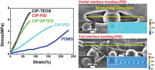
With the technological progress of wearable electronics operated in 5 G network communication system, a stretchable noise suppressor at GHz bandwidth that is reliable under severe deformation coming from the user’s motion should be developed. However, current material systems for the noise suppressor showed a limited stretchability. This study introduces a carbonyl iron powder – polydimethylsiloxane (CIP – PDMS) composite with partially bonded interface as a solution to enhance the stretchability. Modulation of CIP surface to have the partial interface bonding (CIP-PID) results in the ultra large strain of ~165% even at the 40 vol% of CIP-PIDs, while only ~71% of strain is observed for CIPs with the full interface bonding (CIP-FID). According to a microstructural analysis and FEM simulation of the strained composite specimens, when partially bonded to CIP at the interface, the PDMS matrix forms a free surface that can be deformed like pure PDMS, resulting in high stretchability. The wettability of CIP offers protection against eddy current loss while retaining strong magnetic properties, suppressing the EM noise. Thus, the approach eliminates the tradeoff between EM suppression and stretchability.
GRAPHICAL ABSTRACT
摘要
随着在5G网络通信系统中运行的可穿戴电子设备的技术进步,应该开发一种GHz带宽的可伸缩噪声抑制器,它在用户运动产生的严重变形下是可靠的.然而,噪音抑制器的当前材料系统显示出有限的可伸缩性.本研究介绍了一种具有部分键合界面的羰基铁粉-聚二甲基硅氧烷(CIP–PDMS)复合材料,作为增强拉伸性能的解决方案. 对CIP表面进行调制以实现部分界面结合(CIP-PID),即使在CIP-PID的40 vol%下,也会导致约165%的超大应变,而对于具有全界面结合的CIP(CIP-FID),仅观察到约71%的应变.根据应变复合材料试样的微观结构分析和FEM模拟,当部分粘结到界面处的CIP时,PDMS基体形成一个自由表面,可以像纯PDMS一样变形,从而产生高拉伸性.CIP的润湿性可防止涡流损失,同时保持强磁性,抑制EM噪声. 因此,该方法消除了EM抑制和可伸缩性之间的折衷.
1. Introduction
Researchers speculate that the electromagnetic (EM) radiation emanated from wearable electronics operating in the gigahertz (GHz) bandwidth may cause malfunctioning of the devices or pose health hazards to human beings (Jiang et al. Citation2019; Yang et al. Citation2020). Attempts to integrate and miniaturize electronic devices have also increased the risks caused by EM noise (Chen et al. Citation2021; Fan et al. Citation2020; Gupta and Tai Citation2019; Maruthi, Faisal, and Raghavendra Citation2021). Therefore, various types of materials were studied for EM noise suppressors, including micro metal meshes (Asmatulu et al. Citation2020; Jiang et al. Citation2019), polymer-based composites (Guo, Wu, and Yao Citation2021; Maruthi, Faisal, and Raghavendra Citation2021), and aerogels (Chen et al. Citation2021; Xin, Ming-Guo, and Chen Citation2021). Among them, composites with a polymer matrix and magnetic/conductive fillers were considered the most promising for wearable electronics owing to their light weight, tunable elasticity, and moldability (Gao et al. Citation2020; Liang et al. Citation2009; Wang et al. Citation2021; Ying-Ming et al. Citation2020).
As the EM noise-suppression performance of composite materials is largely governed by the magnetic and electrical properties of fillers, the development of filler materials, including carbon-based materials (Fan et al. Citation2020; Gupta and Tai Citation2019; Liang et al. Citation2009; Wang et al. Citation2021), Mxene (Fan et al. Citation2020; Liu et al. Citation2021), GaN (Chen et al. Citation2019), conductive polymer composites (CPCs) (Gao et al. Citation2020; Maruthi, Faisal, and Raghavendra Citation2021), ferrite-based alloy powders (Asmatulu et al. Citation2020; Pan et al. Citation2020), and carbonyl iron powder (CIP), has been thoroughly researched (Jeon, Kim, and Hyeon Kim Citation2019; Seo et al. Citation2022a). Although carbon-based materials and MXenes exhibit efficient noise suppression over a wide wavelength, CIP is regarded the most commercially viable filler material because it can be mass produced for cheap by thermal decomposition and displays a high saturation magnetization and permeability in the GHz bandwidth (Jeon, Kim, and Hyeon Kim Citation2019; Seo et al. Citation2022a).
Stretchability is a desired trait of materials for wearable electronics. When it comes to CIP composites, a high EM noise suppression efficiency is achieved by adding a large amount of filler; however, this reduces the stretchability of the composites. In our previous study, 40 vol% CIP – PDMS composites exhibited 2.25 times the EM noise suppression efficiency of the 20 vol% CIP – PDMS composites (Seo et al. Citation2022a). However, the failure strain was reduced from approximately 145% to 71% as the vol% of CIP decreased from 20 to 40 vol%. As the wearer’s movement induces more than 75% of strain on wearable devices (Chortos, Liu, and Bao Citation2016; Edwards and Marks Citation1995), the stretchability of composites should be enhanced. Additionally, quality of a product should be twice the industry standard of general use. This warrants a method to drastically enhance the stretchability of composites without weakening the noise suppression effect, which is a classic yet unsolved problem in this field (Mondal et al. Citation2018).
Although demonstration to EM noise suppression was not performed, there have been many reports on the stretchable conductors showing excellent stretchability (Chen et al. Citation2021a; Feng et al. Citation2019; Liu et al. Citation2020). For example, Feng et al. demonstrated a thermoplastic polyurethane (PU)/carbon nanotubes (CNTs) composites showing high stretchability of ~250% (Feng et al. Citation2019). Structural design was also effective to enhance the stretchability, where Chen et al. achieved a stretchability of ~100% through the kirigami structure consisting of Mxene and PDMS composite (Chen et al. Citation2021b). Liu et al. also demonstrated a honeycomb structure using copper microcoils/rubber composites showing the strechability of ~100% (Liu et al. Citation2020).
In the similar perspective, several studies have been reported for the noise suppressor with the enhanced stretchability and high EMI absorption performance (Huang et al. Citation2020; Wan et al. Citation2017; Wang et al. Citation2021). For example, Huang et al. proposed 3D-structured composites for EMI noise suppression, where PU foam with 3D sturucture backbone was coated with 4.6 vol% of CNTs, which was then mixed with ecoflex (Huang et al. Citation2020). Although the 3D composites showed the high stretchability of ~150% and EMI shielding efficiency of ~30 dB, but the relatively thick thickness of ~3 mm limited their use for the futuristic miniaturized devices. In the work by Wang et al., thin composite films consisting of graphene oxide and PDMS were developed by using 3D printing method (Wang et al. Citation2021). The developed composite films had a suitable stretchability of ~ 130%, but the EMI shielding efficiency was relatively low showing ~25 dB at 10 GHz. In the other work by Wan et al., a wavy structured-composites consisting of Mxene and themoplastic PU nanofiber was fabricated. The composites showed high EMI shielding efficiency of ~30 dB, but the stretchability was relatively low showing ~70% (Wan et al. Citation2017). Despite of the high stretchability and excellent EM absorption performances of the composites in previous research, their methods utilizing stuructural engineering or expensive nanomaterials were rather complex to be fabricated, which results in the increase in production costs. Therefore, further research is required to develop a composite that can be fabricated via cost-effective methods, while achieving the properties of thin thickness, high stretchability and excellent EM absorption performance in the X-band region, simulatneously.
In this study, we introduced partial interface bonding between CIP and the PDMS matrix to enhance the stretchability of the composite. In a typical CIP – PDMS composite, the imposed strain is localized at the CIP – PDMS interface. As the CIP content is increased to improve noise suppression, the fraction of strain localization at the particle – matrix interface increases, stiffening the composite (Seo et al. Citation2022a). To relax the strain localization, we modified the CIP to partially bond with the PDMS matrix (CIP – PID) at the interface and examined it as a filler for noise suppression composite films. The PID formed a weak and incomplete bond that allowed the PDMS matrix to be stretched without initiating cracks from the stress localization. The stretchability of the CIP – PID composites was twice more than that of the typical composites using CIP with full interface bonding (CIP – FID).
The mechanism by which partial interface bonding enhances the stretchability was examined thoroughly by correlating the microstructural analysis of the strained composites with a finite element analysis (FEM) simulation. In addition, the surface changes of the CIP had no significant effect on its dispersability, as explained by the absolute values of the large Gibbs free wetting enthalpy for both CIP – PID and CIP – FID composites. The potential of CIP – PID/PDMS composites as deformable noise suppressors was confirmed by examining the magnetic properties and EM noise suppression performance. This study provides new insights into classical polymer matrix composites and help overcome the tradeoff between EM noise suppression and stretchability for next-generation wearable electronics that require massive data communication under severe deformation.
2. Materials and method
2.1. Fabrication of CIP – PDMS composites
Polydimethylsiloxane (PDMS; Sylgard-184, Dow Silicones Corporation, Michigan, USA) and CIP (EW grade, BASF SE, Ludwigshafen, Germany) were purchased and used as received. CIP without SiO2 on the surface was also provided by BASF and used as received. The components were mixed by a planetary vacuum mixer (ARV-310, THINKY Corporation, Tokyo, Japan) in two steps. First, CIP and PDMS were mixed without a curing agent at 2,000 rpm in vacuum under 20 kPa for 5 min. Second, a curing agent was added to the mixed samples, and the samples were remixed at 1,200 rpm under 80 kPa for 3 min. The CIP – PDMS mixture was then poured into polytetrafluoroethylene (PTFE) casting molds with dimensions of 40.0 (w) × 30.0 (l) × 0.3 mm (t) and 8.0 (w) × 48.0 (l) × 0.3 mm (t). To remove the air bubbles in the CIP – PDMS mixture, it was degassed under 15 kPa for 3 h in a vacuum oven. Third, the samples were stored in a vacuum oven at 100°C for 2 h.
2.2. Characterization
The microstructures of CIP and CIP – PDMS composites were analyzed using field-emission scanning electron microscopy (FE-SEM, Carl Zeiss AG, Germany). A focused ion beam (FIB) milling device (Quanta 3D FEG, FEI Company (Thermo Fisher Scientific, Oregon, USA) equipped with an energy dispersive X-ray dispersive spectrometry instrument (EDX, NORAN system 7, Thermo Fisher Scientific) was used to characterize the cross-section of CIP and the line profile of Si through the cross-section of CIP. The chemical composition of the CIP surface was analyzed by X-ray photoelectron spectroscopy (×PS, K-alpha+, ThermoFisher Scientific) using an Al – Kα radiation source.
The crystallographic orientation of CIP was measured using X-ray diffraction analysis (×RD, New D8-Advance, Bruker, Newark, DE, AXS, USA) at 40 kV and 40 mA with Cu – Kα photons. The dispersion states of CIP in composites were observed using optical microscopy (OM, BX-51, Olympus, Japan). Stress – strain curves under tensile deformation were analyzed using a rheometer (Compac-100II, Sun Scientific Co. Ltd., Japan) with a maximum load cell of 100 N under a tensile speed of 120 mm/min. The surface energy, and polar and dispersive components of CIP were evaluated from the contact angle values for the polar (deionized (DI) water) and nonpolar (diiodomethane) solvents, which were measured using a drop shape analyzer (DSA-100, KRUSS, Hamburg, Germany).
The Owens, Wendt, Rabel and Kaelble (OWRK) model was used to calculate the surface energy. The EM noise absorption properties of CIP – PDMS composites were measured using a network analyzer (8720D, Hewlett-Packard, USA). The samples were punched into the shape of a donut, with inner and outer diameters of 3.0 and 7.0 mm, respectively, while fixing the inner hole to the holder for the tests. The EM absorption performance was measured at wavelengths of 1–18 GHz with a coaxial waveguide in the same dimensions as the donut shape of the punched samples. The power loss was calculated as follows:
where and
are the reflected and transmitted signals, respectively, measured by the network analyzer.
2.3. Finite element analysis (FEM) simulation
We used numerical modeling to compare the mechanical response of typical CIP – PDMS and CIP – PID/PDMS composites. Only small portion of the sample, i.e., 100 µm × 30 µm × 5 µm, was examined owing to the self-similar characteristic of the PDMS. For CIP – PID/PDMS, partial interface bonding was induced by positioning the voids in the vicinity of CIP. For CIP – PDMS, CIP and PDMS were fully bonded. Fig. S1 illustrates the detailed geometric illustration for the simulation. The size of the CIP particles was averaged to a diameter of 3 µm. The commercial FEM tool COMSOL was employed to replicate the axial stretch of both composites. For fair comparison, a load/force of 100 kPa was applied on one edge of the composite, while the other edge was fixed. The mechanical properties, induced stress and stretching (%),were calculated using the Solid Mechanics module of COMSOL. A refined mesh near the CIP particles was considered to ensure solution convergence. The material properties of PDMS and CIP, including Young’s modulus, Poisson’s ratio and density, were assumed to be 2.05 MPa, 0.495, 0.982 g/cm3, and 211 GPa, 0.29, and 7.86 g/cm3, respectively.
3. Results and discussion
3.1. Characterization of CIP for FID and PID
displays the cross-sectional image of raw CIP constituting CIP – FID. CIP particles are spherical with an average diameter of approximately 1.1 um. The magnetic grade CIPs used as filler in EM noise suppressor were covered with an SiO2 insulating layer, as indicated by the EDX line mapping results in . This layer reduces the eddy current formation between adjacent CIP particless. The SiO2 surface forms a strong chemical bond with the PDMS, [(CH3)2SiO]n, through the (Si – O–Si) covalent bonds between -Si on the silica surface and -Si at the broken PDMS chain. The reaction is as follows.
Figure 1. Cross-sectional scanning electron microscopy (SEM) images of (a) CIP – FID and (b) CIP – PID. Insets illustrate the energy dispersive spectroscopy (EDS) line scan results for Si along the sky blue arrow. Top view of SEM images of (c) CIP – FID and (d) CIP – PID/PDMS composites with 40 vol% of CIP. Inset of (d) is the enlarged SEM image of CIP – PID. (e) XRD patterns of the CIP – FID and CIP – PID. XPS survey data of (f) CIP – FID and (g) CIP – PID. (h) O1s peaks of CIP – FID and (i) CIP – PID. Insets are Si2p peaks. Optical microscopy (OM) images of water droplets on CIP – FID and CIP -PID.
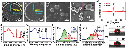
In addition, the physical (O⋅⋅⋅H) bonds created by the interaction between the -OH group on the silicon surface and -O- on the PDMS backbone contributed to the bonding of CIP and the PDMS matrix (Klonos et al. Citation2019; Klonos, Pissis, and Kyritsis Citation2017). Because of the strong adhesion produced by covalent bonding with additional contribution from hydrogen bonding, the SiO2 layer on the raw CIP resulted in strong and full interfacial bonding without forming the free surface of the PDMS matrix at the interface (). To generate the partial interface bond of CIP with the PDMS matrix, we removed the SiO2 layer from the CIP surface.
displays the cross-sectional SEM images of the CIP without an SiO2 layer that can form CIP – PID in a PDMS composite (). The shape of the CIP without SiO2 layer was also spherical, and its EDX mapping results clearly showed the lack of an SiO2 layer on the surface. highlight the XPS analysis results for CIP – FID and CIP – PID. In the survey data in , Si2s and Si2p peaks were observed for the raw CIP, which were not detected for CIP – PID. The CIP – PID composite also had a less intense O1s peak than CIP – FID (). In the O1s and Si2P spectra, CIP – FID consistently produced SiO2 peaks at binding energies of 531.9 and 102.5 eV, respectively (); however, CIP – PID did not produce SiO2 peaks while exhibiting strong C=O bond from the carbonyl group of CIP (). Except for the presence of SiO2 on the surface, no other significant differences were expected in the crystallographic structure between the raw CIP and that without SiO2, because the XRD results displayed a single Fe peak with similar full width half maximum (FWHM) values at the same 2θ value of 44.6° for both CIPs ().
The water contact-angle measurement revealed that the surface of the CIP – PID was more hydrophilic than that of CIP – FID, which might owe to the presence of more -OH groups on the surface of CIP – PID than that of CIP – FID (). Hence, more physical bonding was expected for CIP – PID than CIP – FIDs owing to the presence of more hydroxyl groups on the CIP – PID surface. However, CIP – PID/PDMS composites mostly contain weak hydrogen bonds and lack strong covalent bonds. This results in the formation of partial interface bonds between the CIP without the SiO2 layer and the PDMS matrix, leaving behind the free surface of PDMS at the powder – matrix interface ().
The silica shells formed by coating CIP – PID through a reaction with Si(OC2H5)4 (TEOS) or H2N(CH2)3Si(OC2H5)3 (ATPES) also produced a fully bonded interface between CIP and PDMS similar to that of the CIP – FIDs (Fig. S2). This further confirmed the strong contribution of Si to the interfacial bond. These observations indicated that adhesion promoters such as Si or surfactants should be avoided to form the partially bonded interfaces in the CIP – PDMS composites.
3.2. Dispersibility of CIP – PID and CIP – FID Composites
The surface change of CIP can change its dispersion status in the PDMS matrix, which will influence the mechanical and magnetic performance of the composites. Thus, the change in dispersibility with surface characteristics was evaluated. The dispersion of powder in a liquid matrix proceeds in three steps: (1) wetting of the powder surface in a liquid, (2) mixing of the two components by a mixer, and (Ramirez et al. Citation2020) blocking of the agglomeration after the initial dispersion (Freudig, Hogekamp, and Helmar Citation1999). In such a viscous system of PDMS, powders can be homogenously dispersed only if they can be spontaneously wetted in a liquid matrix (Erik et al. Citation1998; Garg et al. Citation2019). The thermodynamic spontaneity of wetting for powders can be predicted by correlating the surface polarities of the powders and polymer matrix, which is expressed by the Gibbs free wetting enthalpy (ΔG)
where ,
,
,
, and
are the surface tension of the liquid, the dispersion and polar fractions of the surface tension of the liquid matrix and the surface free energy of solid particles, respectively (Harikrishnan et al. Citation2017). The smaller the ΔG, the more spontaneous the wetting of the powder into the polymer matrix (Bayat et al. Citation2021). To calculate ΔG, the surface polarities were evaluated using the contact angle with polar and nonpolar droplets, i.e., DI water and diiodomethane, respectively. The ΔG values of CIP with the different surfaces calculated using the experimental parameters, surface energy and polarity, are listed in .
Table 1. Contact angle, surface tension, and dispersive and polar components of carbonyl iron powder (CIP).
shows the ΔG values of the CIPs with the different surface. The ΔG of raw CIP with (CIP – FID) and without surfacial SiO2 (CIP – PID) were −34.9 and −50.6 mN/m, respectively. The molten PDMS exhibited a relatively high polar component in the surface energy, ~25.27 mN/m, before being cured, resulting in a high polarity of 33.22%. As the CIP – PID composite had a larger polar component than CIP – FID, it had smaller ΔG values than CIP – FID. Furthermore, the ΔG values of CIPs treated with TEOS and APTES were −60.42 and −75.94, respectively, which are smaller compared to those of CIP – PID. Negative ΔG values indicate the presence of a thermodynamically spontaneous wetting system (Bayat et al. Citation2021; Douillard, Zoungrana, and Partyka Citation1995).
Figure 2. (A) Gibbs free wetting enthalpy (ΔG) of CIP with different surfaces. OM images of (b) CIP – FID, (c) CIP – PID, (d) CIP-TEOS and (e) CIP-APTES/PDMS composites with (insets) top views of SEM images.
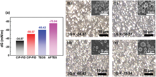
Therefore, all the CIPs examined in this study were expected to be uniformly dispersed in PDMS. display the optical microscopy and SEM images of the PDMS composites using CIPs with the different surfaces. as listed in . Overall, all the tested CIPs were homogeneously dispersed throughout the composites, which can be attributed to the negative ΔG of all the CIPs. However, the CIP – FID composites had more agglomeration than CIP – PID, albeit small (). In addition, CIP-based composites treated with TEOS and APTES had smaller agglomeration compared to the CIP – PID composites (). These trends are consistent with the results of ΔG, with CIP – FID having the largest ΔG. Therefore, the partial bonding of CIP with PDMS at the interface was confirmed to enhance the dispersibility of the composites.
3.3. Mechanical properties of CIP – PID and CIP – FID composites
Next, the mechanical responses of the CIP – PID and CIP – FID composites under tensile deformation were evaluated. show the stress – strain curves of the CIP – FID and CIP – PID composites with CIP contents varied from 0 to 40 vol%. Overall, the CIP – PID composites exhibit significantly higher failure strain values than the CIP – FID composites at the same filler content, which are comparable to those of pure PDMS. CIP – PID had a failure strain of 168.5% even with 40 vol% of filler, which is twice that of CIP – FID. The failure strain of CIP – FID can be enhanced to 165.4% by decreasing the filler content to 10 vol%, albeit at the expense of noise suppression performance because the filler must replace a sizable percentage of magnetic particles. This tradeoff will be discussed in Section 3.5. The tensile strength of the composites exhibited a similar trend;, the tensil strength of CIP – FID increased by a larger margin than that of CIP – PID as the filler content was increased. However, the strength of pure PDMS itself is 4.16 MPa, which is sufficient for various wearable electronics applications (Zhang et al. Citation2021).
Figure 3. Stress – strain curves of (a) CIP – FID and (b) CIP – PID/PDMS composites with different CIP contents and (c) of composites using CIP with different surfaces. Cross-sectional SEM images of (d) CIP – PID and (e) CIP – FID/PDMS composites under 140% stretching. Insets depict the SEM images of CIP – PID and CIP – FID before stretching.
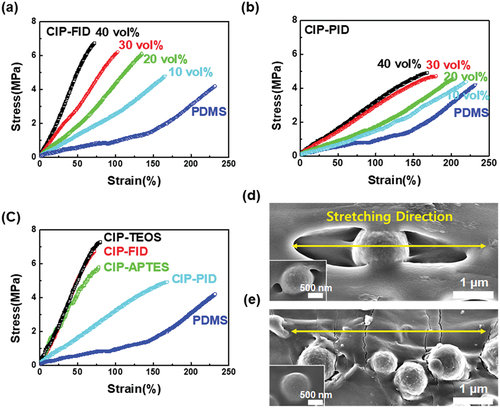
The science behind the enhanced stretchability of CIP – PID can be explained by the ability of the partially bonded interface to accommodate the induced strain by stretching the free surface of the PDMS matrix. As depicted in , the complete bonding between CIP and PDMS matrix in CIP – FID initiated cracks through the particle – matrix interface (). Under this condition, the imposed strain is localized at the interface, resulting in brittle fracture evident by the cracks propagating along the interface ().
In CIP – FID, under complete bonding, brittle fracture became more prominent as the CIP content was increased. Thus, the CIP – FID composites became stiff. In CIP – PDMS, however, the CIP particles were partially bonded with the PDMS matrix, forming a free surface of the PDMS matrix (). The weak and incomplete bonding of PID at the interface allowed the PDMS matrix to be stretched without crack initiation from the stress localization under tensile deformation.
d and e display the SEM images of the CIP – PID composites at 10 vol% of filler under 200% stretching. As observed in the figure, the free surface of the CIP – PID composites has been stretched. This relaxed the imposed strain without heavy strain localization at the powder – matrix interface. Thus, stretchability of the composites was enhanced. The enhanced dispersion states of CIP – PID cannot be the reason for the increased stretchability, because mechanical properties of the CIP treated with APTES and TEOS, which showed a greater degree of dispersion in the composites, behaved similarly as those of the CIP – FID/PDMS composites (Fig. S3). The CIP treated with APTES and TEOS formed a fully bonded interface with PDMS as with CIP – FID, as discussed in Section 3.1. This confirms partial interfacial bonding as the main contributor to the enhancement of the stretchability of CIP – PID/PDMS ().
3.4. FEM simulation of the mechanical behaviors of CIP – PID- and CIP – FID-based PDMS composites
To understand the experimental observations, the CIP – PID and CIP – FID composite models were numerically simulated. As the composite has self-similar topology, we stretched only a small portion of it in the simulation (see Section 2 for details). In the simulation, a tensile load of 100 KPa was imposed at one end of the composites, while keeping the other end fixed. This helped observe the total change in stretchability and the stress distribution in the composites. a and b show the numerical results of of stretchability of the CIP – PID- and CIP – FID-based PDMS composites. The CIP – FID composite had a stretchability of 3.6% (), while the CIP – PID composite was stretched by 4.40% ().
Figure 4. Numerically calculated displacements of (a) CIP – FID- and (b) CIP – PID-based PDMS composites under tensile load of 100 kPa. Calculated stress distribution of (c) CIP – FID- and (d) CIP – PID-based PDMS composites under 100 kPa.
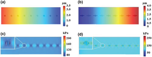
The holes or voids in the CIP – PDMS interface of CIP – PID composites were stretched along the tensile direction, contributing to the enhanced stretchability. c and d presents the von Mises stress distribution in the composites under a tensile stress of 100 KPa. At approximately 2.2 times that in the PDMS matrix, the largest level of stress in the case of the CIP – FID composite was observed at the CIP – PDMS matrix interface ().
However, the CIP – PID composite exhibited a uniform stress distribution throughout (). The level of stress at the interface in this case is significantly smaller than that in the case of CIP – FID. The stress is relaxed by stretching the holes at the interface in the CIP – PID composites, resulting in the smaller stress concentration at the interface compared to the CIP – FID composite. These results are consistent with the experimental observation, where the stretchability of CIP – PID composites was enhanced by stretching the free space of the PDMS matrix formed in the partially bonded interface of the CIP – PID composites ().
3.5. EM noise suppression performance of CIP – PID and CIP – FID composites
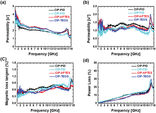
In general, the eddy currents generated at the CIP – CIP interface degrade the EM noise suppression performance of the composites. The function of the SiO2 layer is to prevent these eddy currents (Chen et al. Citation2019; Shukla Citation2019). Therefore, the removal of the layer on the CIP surface will degrade the noise suppression performance. To confirm the effect of SiO2 layer at the CIP surfaces on noise suppression performance of the PDMS composites, we measured the magnetic absorption characteristics of the PDMS composites with CIP – PID and CIP – FID ().
Figure 5. (A) Real and (b) imaginary parts of the complex permeability of various CIP – PDMS composites in the frequency range of 1–18 GHz. (c) Magnetic loss tangent and (d) power loss of the CIP – PDMS composites in the range of 1–18 GHz.
The EM wave-absorption performance is influenced mainly by complex permittivity and permeability, which are expressed as follows:
( (Ramirez et al.)
where the real parts () and imaginary parts (
) indicate the storage capability and the losses of electric and magnetic energies, respectively (Gong et al. Citation2009; Sista et al. Citation2021). As the PDMS is an electrical insulator, the CIP – PDMS composites had considerably lower complex permittivity and dielectric loss tangent
values than the permeability and magnetic loss tangent
(Fig. S4). Therefore, the EM absorption efficiency of CIP – PDMS composites is primarily governed by the magnetic absorption properties of the CIP (Yin et al. Citation2013). illustrate the results of the real part and imaginary part
of the complex permeability of the PDMS composites using CIPs treated for different surfaces measured as a function of the EM wave frequency in the range of 1–18 GHz (Seo et al. Citation2022a).
The CIP – PDMS composites absorb more EM waves as the filler contents are increase, owing to the strengthened magnetic properties of the composites achieved by the increasing the content of CIP with high magnetization (Gong et al. Citation2009; Niandu et al. Citation2016). Thus, the maximum CIP content of composites was fixed at approximately 40 vol% for the EM absorption tests. Interestingly, the composites with CIP – PID exhibited similar real and imaginary values in the entire frequency range as the composites with CIP – FID.
The composites with APTES- and TEOS-coated CIP also exhibited similar trends in terms of the change in permeability as a function of the EM wave frequency as the composites with CIP – PID or CIP – FID. Because of the similar values of the real and imaginary parts of permeability, the change in magnetic loss tangent calculated by Eq. (6) yielded similar trends across the frequency range, as illustrated in . The EM wave absorption converted into heat energy is expressed as the power loss
where t, ,
, and
are the sample thickness, frequency, relative permeability, and conductivity, respectively (Kim et al. Citation2007, Citation2019; Sushmita et al. Citation2019). depicts the variation of power loss of the PDMS composites with CIP content in the frequency range of 1–18 GHz. The degree of power loss in the test frequency range was also similar for all the PDMS composites with different CIP contents. These results indicated that the surface change of CIP had no significant effect on the EM noise suppression performance. As discussed in Section 3.3, the good wettability of CIP fillers in the PDMS matrix allowed them to have an insulating PDMS layer encapsulating their surfaces, which functions as a substitute SiO2 layer.
Thus, even without the SiO2 layer, the CIP contributed to a similar noise-suppression performance. Combined with the tensile test results, the proposed CIP – PDMS composites with partial interface bonding can deform without sacrificing EM noise suppression performance despite surface strain. The findings will provide insights on overcoming the tradeoff between stretchability and functional performance governed by filler content generally observed in polymer matrix composites.
4. Conclusions
This study proposed the modification of the surface of CIPs to have weak PID, and thus resolve the tradeoff between stretchability and EM noise supression commonly observed in polymer matrix composites. In general, CIP is covered in a layer of SiO2 to prevent eddy current generation, which results in strong FID with PDMS through the (Si – O–Si) covalent bonds. We discovered that removing the SiO2 layer results in the formation of PID with the PDMS matrix. This approach enhanced the dispersion of CIP in PDMS owing to the increased wettability. The tensile test results of the PDMS composites with CIP – PID and CIP – FID indicated that the surface modification of CIP achieved an ultra-high stretchability of approximately 168% even at a high filler content, approximately 40 vol%, whereas the untreated CIP exhibited a limited strain value of approximately 71%. The microstructural analysis and FEM simulations revealed that the free surface of PDMS formed at the interface between CIP – PID and PDMS can be stretched without initiating cracks, as observed in the typical CIP forming FID with PDMS. The EM noise suppression performance of the PDMS composites with CIP – PID and CIP – FID was tested, which confirmed no significant changes after surface modification. Overall performance of the developed noise suppression composites with CIP-PID was comparable to those of previous researches using different strategies to achieve the high stretchability and EM absoption property () (Chen et al. Citation2021b; Feng et al. Citation2019; Huang et al. Citation2020; Jia et al. Citation2019; Jung et al. Citation2017; Seo et al. Citation2022b; Wan et al. Citation2017; Wang et al. Citation2021; Yuan et al. Citation2020). Although several reports showed better EMI shielding efficiency than the results of this study, the combination of mass-producible and low cost CIPs with a simple mixing process for the composite fabrication will be a promising option for stretchable composites for EM noise suppression, especiallty for industries.
Table 2. Comparison of mechanical and magnetic performances of different composites.
Acknowledgments
This work was supported by the National Research Foundation of Korea (NRF) (Nos. 2021R1F1A1054886 and 2021K1A3A1A74096164).
Disclosure statement
No potential conflict of interest was reported by the author(s).
Additional information
Funding
References
- Asmatulu, R., P. K. Bollavaram, V. R. Patlolla, I. M. Alarifi, and W. S. Khan. 2020. Investigating the effects of metallic submicron and nanofilms on fiber-reinforced composites for lightning strike protection and EMI shielding. Advanced Composites and Hybrid Materials 3 (1):66–14. doi:10.1007/s42114-020-00135-7.
- Bayat, A., M. Ebrahimi, S. R. Ardekani, E. S. Iranizad, and A. Z. Moshfegh. 2021. Extended Gibbs free energy and laplace pressure of ordered hexagonal close-packed spherical particles: A wettability study. Langmuir 37 (28):8382–92. doi:10.1021/acs.langmuir.1c00343.
- Chen, W., L. X. Liu, H. B. Zhang, and Z. Z. Yu. 2021a. Kirigami-inspired highly stretchable, conductive, and hierarchical Ti3C2Tx MXene films for efficient electromagnetic interference shielding and pressure sensing. ACS Nano 15 (4):7668–81. doi:10.1021/acsnano.1c01277.
- Chen, W., L.-X. Liu, H.-B. Zhang, and Y. Zhong-Zhen. 2021b. Kirigami-inspired highly stretchable, conductive, and hierarchical Ti3C2Tx MXene films for efficient electromagnetic interference shielding and pressure sensing. ACS Nano 15 (4):7668–81. doi:10.1021/acsnano.1c01277.
- Chen, Q., L. Li, Z. Wang, Y. Ge, C. Zhou, and J. Yi. 2019. Synthesis and enhanced microwave absorption performance of CIP@ [email protected] ferrite composites. Journal of Alloys and Compounds 779:720–27. doi:10.1016/j.jallcom.2018.11.112.
- Chen, Y., Y. Yang, Y. Xiong, L. Zhang, W. Xu, G. Duan, C. Mei, S. Jiang, Z. Rui, and K. Zhang. 2021.Porous aerogel and sponge composites: Assisted by novel nanomaterials for electromagnetic interference shielding. Nano Today 38: 101204.doi: 10.1016/j.nantod.2021.101204
- Chen, X., J. Yu, S. Kong, Z. Wu, X. Fang, and L. Wen. 2019. Towards real-time advancement of underwater visual quality with GAN. IEEE Transactions on Industrial Electronics 66 (12):9350–59. doi:10.1109/TIE.2019.2893840.
- Chortos, A., J. Liu, and Z. Bao. 2016. Pursuing prosthetic electronic skin. Nature Materials 15 (9):937–50. doi:10.1038/nmat4671.
- Douillard, J. M., T. Zoungrana, and S. Partyka. 1995. Surface Gibbs free energy of minerals: Some values. Journal of Petroleum Science and Engineering 14 (1):51–57. doi:10.1016/0920-4105(95)00018-6.
- Edwards, C., and R. Marks. 1995. Evaluation of biomechanical properties of human skin. Clinics in Dermatology 13 (4):375–80. doi:10.1016/0738-081X(95)00078-T.
- Erik, D., T. W. Ebbesen, A. Krishnan, M.J.T. Michael . 1998. Wetting of single shell carbon nanotubes Advanced Materials, 10 (17):1472–75.
- Fan, Z., D. Wang, Y. Yuan, Y. Wang, Z. Cheng, Y. Liu, and Z. Xie. 2020.A lightweight and conductive MXene/graphene hybrid foam for superior electromagnetic interference shielding. Chemical Engineering Journal 381: 122696.doi: 10.1016/j.cej.2019.122696
- Feng, D., D. Xu, Q. Wang, and P. Liu. 2019. Highly stretchable electromagnetic interference (EMI) shielding segregated polyurethane/carbon nanotube composites fabricated by microwave selective sintering. Journal of Materials Chemistry C 7 (26):7938–46. doi:10.1039/c9tc02311a.
- Freudig, B., S. Hogekamp, and J. Helmar. 1999. Dispersion of powders in liquids in a stirred vessel. Chemical Engineering Schubert, and Processing: Process Intensification 38 (4–6): 525–32.
- Gao, W., N. Zhao, T. Yu, J. Xi, A. Mao, M. Yuan, H. Bai, and C. Gao. 2020. High-efficiency electromagnetic interference shielding realized in nacre-mimetic graphene/polymer composite with extremely low graphene loading. Carbon 157:570–77. doi:10.1016/j.carbon.2019.10.051.
- Garg, P., A. Jamwal, D. Kumar, K. Kumar Sadasivuni, C. Mustansar Hussain, and P. Gupta. 2019. Advance research progresses in aluminium matrix composites: Manufacturing & applications. Journal of Materials Research and Technology 8 (5):4924–39. doi:10.1016/j.jmrt.2019.06.028.
- Gong, Y. X., L. Zhen, J. T. Jiang, C. Y. Xu, and W. Z. Shao. 2009. Preparation of CoFe alloy nanoparticles with tunable electromagnetic wave absorption performance. Journal of Magnetism and Magnetic Materials 321 (22):3702–05. doi:10.1016/j.jmmm.2009.07.019.
- Guo, Y., Q. Wu, and C. Yao. 2021. Aggregation behavior of a pH-responsive cationic–nonionic silicone surfactant in aqueous solution. Colloid and Interface Science Communications 42:100401. doi:10.1016/j.colcom.2021.100401.
- Gupta, S., and N.-H. Tai. 2019. Carbon materials and their composites for electromagnetic interference shielding effectiveness in X-band. Carbon 152:159–87. doi:10.1016/j.carbon.2019.06.002.
- Harikrishnan, A. R., S. K. Das, P. K. Agnihotri, and P. Dhar. 2017. Particle and surfactant interactions effected polar and dispersive components of interfacial energy in nanocolloids. Journal of Applied Physics 122 (5). doi: 10.1063/1.4997123.
- Huang, K., M. Chen, G. He, X. Hu, W. He, X. Zhou, Y. Huang, and Z. Liu. 2020. Stretchable microwave absorbing and electromagnetic interference shielding foam with hierarchical buckling induced by solvent swelling. Carbon 157:466–77. doi:10.1016/j.carbon.2019.10.059.
- Jeon, S., J. Kim, and K. Hyeon Kim. 2019. Microwave absorption properties of graphene oxide capsulated carbonyl iron particles. Applied Surface Science 475:1065–69. doi:10.1016/j.apsusc.2019.01.017.
- Jiang, Z. Y., W. Huang, L. S. Chen, and Y. H. Liu. 2019. Ultrathin, lightweight, and freestanding metallic mesh for transparent electromagnetic interference shielding. Optics Express 27 (17):24194–206. doi:10.1364/OE.27.024194.
- Jiang, D., V. Murugadoss, Y. Wang, J. Lin, T. Ding, Z. Wang, Q. Shao, C. Wang, H. Liu, N. Lu, et al. 2019. Electromagnetic interference shielding polymers and nanocomposites - a review. Polymer Reviews 59 (2):280–337. doi:10.1080/15583724.2018.1546737.
- Jia, L.-C., L. Xu, F. Ren, P.-G. Ren, D.-X. Yan, and L. Zhong-Ming. 2019. Stretchable and durable conductive fabric for ultrahigh performance electromagnetic interference shielding. Carbon 144:101–08. doi:10.1016/j.carbon.2018.12.034.
- Jung, J., H. Lee, I. Ha, H. Cho, K. Kyu Kim, J. Kwon, P. Won, S. Hong, and K. Seung Hwan. 2017. Highly stretchable and transparent electromagnetic interference shielding film based on silver nanowire percolation network for wearable electronics applications. ACS Applied Materials & Interfaces 9 (51):44609–16. doi:10.1021/acsami.7b14626.
- Kim, H., S. Park, S. Kim, and Y. Seo. 2019. Microwave absorption and shielding property of Fe–Si–Al alloy/MWCNT/polymer nanocomposites. Langmuir 35 (21):6950–55. doi:10.1021/acs.langmuir.8b04160.
- Kim, S. W., Y. W. Yoon, S. J. Lee, G. Y. Kim, Y. B. Kim, Y. Yeo Chun, and K. S. Lee. 2007. Electromagnetic shielding properties of soft magnetic powder–polymer composite films for the application to suppress noise in the radio frequency range. Journal of Magnetism and Magnetic Materials 316 (2):472–74. doi:10.1016/j.jmmm.2007.03.133.
- Klonos, P. A., O. V. Goncharuk, E. M. Pakhlov, D. Sternik, A. Deryło-Marczewska, A. Kyritsis, V. M. Gun’Ko, and P. Pissis. 2019. Morphology, molecular dynamics, and interfacial phenomena in systems based on silica modified by grafting polydimethylsiloxane chains and physically adsorbed polydimethylsiloxane. Macromolecules 52 (7):2863–77. doi:10.1021/acs.macromol.9b00155.
- Klonos, P., P. Pissis, and A. Kyritsis. 2017. Effects of hydration/dehydration on interfacial polymer fraction and dynamics in nanocomposites based on metal–oxides and physically adsorbed polymer. The Journal of Physical Chemistry C 121 (35):19428–41. doi:10.1021/acs.jpcc.7b05267.
- Liang, J., Y. Wang, Y. Huang, Y. Ma, Z. Liu, J. Cai, C. Zhang, H. Gao, and Y. Chen. 2009. Electromagnetic interference shielding of graphene/epoxy composites. Carbon 47 (3):922–25. doi:10.1016/j.carbon.2008.12.038.
- Liu, C., J. Cai, P. Dang, X. Li, and D. Zhang. 2020. Highly stretchable electromagnetic interference shielding materials made with conductive microcoils confined to a honeycomb structure. ACS Applied Materials & Interfaces 12 (10):12101–08. doi:10.1021/acsami.0c00034.
- Liu, H., R. Fu, X. Su, B. Wu, H. Wang, Y. Xu, and X. Liu. 2021.Electrical insulating MXene/PDMS/BN composite with enhanced thermal conductivity for electromagnetic shielding application. Composites Communications 23: 100593.doi: 10.1016/j.coco.2020.100593
- Maruthi, N., M. Faisal, and N. Raghavendra. 2021. Conducting polymer based composites as efficient EMI shielding materials: A comprehensive review and future prospects. Synthetic Metals 272. doi:10.1016/j.synthmet.2020.116664.
- Mondal, S., P. Das, S. Ganguly, R. Ravindren, S. Remanan, P. Bhawal, T. Kanti Das, and N. Ch Das. 2018. Thermal-air ageing treatment on mechanical, electrical, and electromagnetic interference shielding properties of lightweight carbon nanotube based polymer nanocomposites. Composites Part A: Applied Science and Manufacturing 107:447–60. doi:10.1016/j.compositesa.2018.01.025.
- Niandu, W., X. Liu, C. Zhao, C. Cui, and A. Xia. 2016. Effects of particle size on the magnetic and microwave absorption properties of carbon-coated nickel nanocapsules. Journal of Alloys and Compounds 656:628–34. doi:10.1016/j.jallcom.2015.10.027.
- Pan, W., J. Wang, L. Yong-Ping, X.-B. Sun, J.-P. Wang, X.-X. Wang, J. Zhang, H.-D. You, Y. Gui-Feng, and Y.-Z. Long. 2020. Facile preparation of highly stretchable TPU/Ag nanowire strain sensor with spring-like configuration. Polymers 12 (2):339.
- Ramírez, J., A. D. Urbina, A. T. Kleinschmidt, M. Finn, S. J. Edmunds, G. L. Esparza, and D. J. Lipomi. 2020. Exploring the limits of sensitivity for strain gauges of graphene and hexagonal boron nitride decorated with metallic nanoislands. Nanoscale, 12(20): 11209–11221. 10.1039/D0NR02270E
- Seo, Y., S. Ko, H. Ha, N. Qaiser, M. Leem, S. Jo Yoo, J. Hyeon Jeong, K. Lee, and B. Hwang. 2022a. Stretchable carbonyl iron powder/polydimethylsiloxane composites for noise suppression in gigahertz bandwidth. Composites Science and Technology 218. doi:10.1016/j.compscitech.2021.109150.
- Seo, Y., S. Ko, H. Ha, N. Qaiser, M. Leem, S. Jo Yoo, J. Hyeon Jeong, K. Lee, and B. Hwang. 2022b. Stretchable carbonyl iron powder/polydimethylsiloxane composites for noise suppression in gigahertz bandwidth. Composites Science and Technology 218:109150. doi:10.1016/j.compscitech.2021.109150.
- Shukla, V. 2019. Review of electromagnetic interference shielding materials fabricated by iron ingredients. Nanoscale Advances 1 (5):1640–71. doi:10.1039/c9na00108e.
- Sista, K. S., S. Dwarapudi, D. Kumar, G. Ranjan Sinha, and A. P. Moon. 2021.Carbonyl iron powders as absorption material for microwave interference shielding: A review. Abhijeet Premkumar %J Journal of Alloys Moon, and Compounds 853: 157251.doi: 10.1016/j.jallcom.2020.157251
- Sushmita, K., A. V. Menon, S. Sharma, A. C. Abhyankar, G. Madras, and S. Bose. 2019. Mechanistic insight into the nature of dopants in graphene derivatives influencing electromagnetic interference shielding properties in hybrid polymer nanocomposites. The Journal of Physical Chemistry C 123 (4):2579–90. doi:10.1021/acs.jpcc.8b10999.
- Wang, G., X. Liao, F. Zou, P. Song, W. Tang, J. Yang, and G. Li. 2021. “Flexible TPU/MWCNTs/BN composites for frequency-selective electromagnetic shielding and enhanced thermal conductivity.” Composites Communications 28. doi: 10.1016/j.coco.2021.100953.
- Wang, Z., W. Yang, R. Liu, X. Zhang, H. Nie, and Y. Liu. 2021. Highly stretchable graphene/polydimethylsiloxane composite lattices with tailored structure for strain-tolerant EMI shielding performance. Composites Science and Technology 206:108652. doi:10.1016/j.compscitech.2021.108652.
- Wan, Y.-J., P.-L. Zhu, Y. Shu-Hui, R. Sun, C.-P. Wong, and W.-H. Liao. 2017. Ultralight, super-elastic and volume-preserving cellulose fiber/graphene aerogel for high-performance electromagnetic interference shielding. Carbon 115:629–39. doi:10.1016/j.carbon.2017.01.054.
- Xin, W., M. Ming-Guo, and F. Chen. 2021. Silicone-coated MXene/Cellulose nanofiber aerogel films with photothermal and joule heating performances for electromagnetic interference shielding. ACS Applied Nano Materials 4 (7):7234–43. doi:10.1021/acsanm.1c01185.
- Yang, X., S. Fan, Y. Li, Y. Guo, Y. Li, K. Ruan, S. Zhang, J. Zhang, J. Kong, and J. Gu. 2020. Synchronously improved electromagnetic interference shielding and thermal conductivity for epoxy nanocomposites by constructing 3D copper nanowires/thermally annealed graphene aerogel framework. Composites Part A: Applied Science and Manufacturing 128. doi:10.1016/j.compositesa.2019.105670.
- Yin, C., Y. Cao, J. Fan, L. Bai, F. Ding, and F. Yuan. 2013. Synthesis of hollow carbonyl iron microspheres via pitting corrosion method and their microwave absorption properties. Applied Surface Science 270:432–38. doi:10.1016/j.apsusc.2013.01.044.
- Ying-Ming, L., C. Deng, Z.-Y. Zhao, L.-X. Han, P. Lu, and Y.-Z. Wang. 2020. Carbon fiber-based polymer composite via ceramization toward excellent electromagnetic interference shielding performance and high temperature resistance. Composites Part A: Applied Science and Manufacturing 131. doi:10.1016/j.compositesa.2020.105769.
- Yuan, W., J. Yang, F. Yin, Y. Li, and Y. Yuan. 2020. Flexible and stretchable MXene/Polyurethane fabrics with delicate wrinkle structure design for effective electromagnetic interference shielding at a dynamic stretching process. Composites Communications 19:90–98. doi:10.1016/j.coco.2020.03.003.
- Zhang, Y., M. Li, X. Han, Z. Fan, H. Zhang, and Q. Li. 2021. High-strength and highly electrically conductive hydrogels for wearable strain sensor. Chemical Physics Letters 769. doi:10.1016/j.cplett.2021.138437.