
 ?Mathematical formulae have been encoded as MathML and are displayed in this HTML version using MathJax in order to improve their display. Uncheck the box to turn MathJax off. This feature requires Javascript. Click on a formula to zoom.
ABSTRACT
In the study, Natural jute composite materials, which have environmental advantages due to their easily degradable nature were drilled with different processing parameters and the effects of thrust force, vibration and temperature changes on hole quality were investigated. The effect of feed and spindle speed was statistically analyzed using ANOVA method. The thrust force, vibration and temperature factors that occur depending on the drilling parameters vary and affect the roughness and delamination values. The effect of feed and speed on thrust force was calculated as 97.87% and the feed effect (90.85%) is far greater than the speed (9.15%). The effect of drilling parameters on vibration is statistically insignificant due to the different spread behavior in the layers of the composite material (R2 = 0.2329). However, feed effect on vibration (94.6%) is greater than the speed effect (6.06%). The temperature is affected by 96.93% of the drilling parameters and the speed is 84.16% and the feed is 15.83%. The roughness effect depending on the drilling parameters is measured as 84.91%. The effect of speed on roughness (90.26%) is greater than the feed (9.73%). It has been determined that this situation is mostly related to vibration and temperature.
摘要
在研究中,天然黄麻复合材料由于其易于降解的性质而具有环境优势,采用不同的工艺参数进行钻孔,并研究了推力、振动和温度变化对钻孔质量的影响. 使用方差分析方法对进给和主轴速度的影响进行统计分析. 根据钻孔参数产生的推力、振动和温度因素会变化,并影响粗糙度和分层值. 进给和速度对推力的影响计算为97.87%,进给效果(90.85%)远大于速度(9.15%). 由于复合材料层中的不同扩散行为,钻孔参数对振动的影响在统计学上是不显著的(R2 = 0.2329). 然而,进给对振动的影响(94.6%)大于速度的影响(6.06%). 温度受96.93%的钻井参数影响,速度为84.16%,进料量为15.83%. 根据钻孔参数测量的粗糙度影响为84.91%. 速度对粗糙度的影响(90.26%)大于进给(9.73%). 已经确定,这种情况主要与振动和温度有关.
Introduction
In line with the increasing material needs in industrial applications, the demand for reinforced composites such as carbon, glass and Kevlar fibers is also increasing. However, these materials are not easily biodegradable and their use is restricted due to environmental factors (Gharde and Kandasubramanian Citation2019). For this reason, high-strength composites are developed from natural fibers as an alternative to plants such as bamboo, jute, coconut, fruits and vegetables in reinforcement materials. In this context, especially Europe’s automobile industries have started to widely use natural fiber composites for interior and exterior parts of automobile bodies in order to comply with strict environmental requirements (Khan, Hameed Sultan, and Ariffin Citation2018). Jute material is used extensively in plant fibers due to its unlimited availability, low cost, low density, not posing much threat to health, important processing advantages, advanced mechanical properties, good acoustics, thermal insulation and low water retention rate. In general, as in other vegetable fibers, in the use of jute material, the problem of thermal and moisture absorption to dissolve the fibers is seen. In order to eliminate these problems, chemical applications are made to jute fibers. Jute material is used in many applications in aerospace, defense, construction and automotive sectors, especially due to its sound, heat and moisture retention properties. Jute composite materials are produced and combined in certain sizes.
Although parts are produced close to the desired shape, jute composite components must be machined to meet tolerance requirements in assembly. Drilling is the most popular and widely used process in the industry for the assembly of composite components (Xu et al. Citation2016). The quality of these holes, mostly made in conventional ways, depends on the cutting parameters, tool geometry and tool material. During the drilling process, it can cause serious damages such as delamination in the layers of the composite, especially due to the feed thrust force (Malik, Ahmad, and Gunister Citation2021). Delamination affects the quality of the hole and the strength of the composite (Nasir, Azmi, and Khalil Citation2022). In particular, problems related to the processing of composite materials should be addressed with consideration of the potential applications of these materials. In the literature, plates prepared with different natural composite components were drilled with different processing parameters, and delamination and surface quality were investigated. The basis of drilling problems is related to the parameters used in the process. When the studies carried out in this context are examined;
(Jayabal, Natarajan, and Sekar Citation2011) aimed to develop a regression model to optimize the drilling behavior of glass-coconut fiber-polyester hybrid composite. In their results, it was stated that the feed rate plays an important role in the drilling of this type of composites.
(Abilash and Sivapragash Citation2016) investigated the effects of processing parameters (500,860,1360 rpm; 18,26,34 mm/min) and different drill diameters (Ø 4,6,8 mm) on delamination formation in bamboo fiber reinforced polyester composites. It was examined the effect of different processing parameters on delamination of developed composites and was found that feed rate and drill diameter were effective parameters in delamination formation.
(Choudhury, Srinivas, and Debnath Citation2022) investigated the formation of delamination and surface roughness in the drilling of lignocellulosic fiber reinforced polymer composites. Experimental research was carried out using 4-facet, 8-facet, dagger, step and parabolic drill bits in combination of different feed (8,16,22.4 mm/min) and spindle speed (710,1400,2000 rpm) of the drill bit.
(Rezghi Maleki et al. Citation2019) used different feed rates (0.05,0.125,0.2 mm/rev), spindle speed (500,1500,2500 rpm) and three different drill bit types (twist-CoroDrill854-CoroDrill856) for drilling flax/epoxy composites. In the study, it was investigated the effects of drilling parameters on delamination and hole quality. In the experimental results, it was stated that the delamination factor and surface roughness were significantly affected by the drill bit, but not by the feed and spindle speed.
(Shadrach Jeya Sekaran and Palani Kumar Citation2019) evaluated the delamination and surface roughness of the drilling process of woven sisal and aloe vera natural fiber polymer composites. In their current research, experiments were carried out using carbide drill bits at three different drill diameters (6,8,10 mm), three different spindle speed (250,500,750 rpm) and three different feed rates (20,40,60 mm/min). It was observed less delamination and surface roughness when drilling sisal natural fiber polymer composite at high speed and feed rate. In the study, it was concluded that delamination and surface roughness occur in holes of different diameters in natural fiber epoxy composite material.
(Kiran et al. Citation2019) processing parameters of delamination, torque and thrust forces occurring in drilling of sisal fiber reinforced epoxy composites (450,852,1260,1860,2700 rpm; 30,40,50,60,70 mm/min; Ø 4,6,8,10,12 mm) using ANOVA and Gray regression analysis. The results show that the quality of the drilled hole can be improved by selecting the optimum machining condition.
(Belaadi et al. Citation2020) studied the mechanical characterization and optimization of the delamination factor in the drilling of bidirectional jute fiber reinforced polymer biocomposites. In the experiments, different spindle speed (355,710,1400 rev/min), feed rate (50,108,190 mm/min) and tool diameter (5,7,10 mm) and drill material (HSS_TiN-HSS-brad-spur drill) bits) were used. It was developed an analysis of variance (ANOVA) for all processing parameters. In their results, it was recommended 51 mm/min feed rate, 1160 rev/min revolution rate and 5 mm drill for optimum delamination factor.
(Kumar et al. Citation2022) aimed to find the minimum thrust that the drilling parameters of Palmyra-based composites would create during chip removal. In other study (Mohan Kumar et al. Citation2021) investigated the thrust forces in the drilling behavior of abaca fiber reinforced polymer composites and Kevlar reinforced epoxy polymer composites. In the experimental study, 4 different drill bits (candlestick (T1), core (T2), standard twist drill (T3), and step cone (T4)), 3 different feeds (30,45,60 m/min), and spindle speed (1000,1500,2000 rpm) were used. It was stated that the thrust force decreased at lower speed and revolutions. In addition, it was found lower thrust force formation in drilling operations performed using T1 drill bits compared to other drill bits.
(Ellenberger et al. Citation2022) investigated the drilling process of composites produced using polyurethane foam using different fiber additives (Pinus sawdust, hybrid Pinus sawdust and sisal fibers), taking into account the surface damage and the resulting temperatures during the drilling operation. Different spindle speed (1000,2000,3000 rpm), feed rate (0.05,0.10,0.15 mm/rev) and cutting speeds (18.75,35.7,56.25 m/min) were used in the experiments. It was concluded that lower cutting speed and feed are the optimum parameters.
Studies on the subject with different natural materials have generally focused on delamination and surface roughness. The effects of up to two drilling factors on drilling quality were explained in the studies. In this study, unlike the literature, the results of delamination and surface roughness by drilling the plates produced with jute fiber composite material, the variable effects of drilling parameters, thrust force, vibration and temperature have been extensively discussed. The effect of each drilling factor on the other and on quality is explained. For this purpose, the delamination and surface roughness of the jute fiber reinforced composite material were investigated by drilling at high speed with different parameter values. Vibration, thrust force, temperature measurements were made during drilling and the effects of the data on delamination and surface roughness were investigated. The delamination factor (fd) was calculated by dividing the surface area values over the image of the delamination region.
Material and method
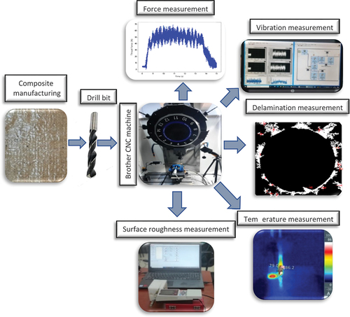
In this study, the effects of drilling parameters on hole quality were investigated in drilling of jute fiber reinforced material. Thrust force, temperature and vibration measurements were measured during the drilling process. After drilling, delamination and surface roughness were measured. All results were evaluated statistically. The experimental setup is shown in .
Figure 1. Experimental setup.
Fabrication of composites
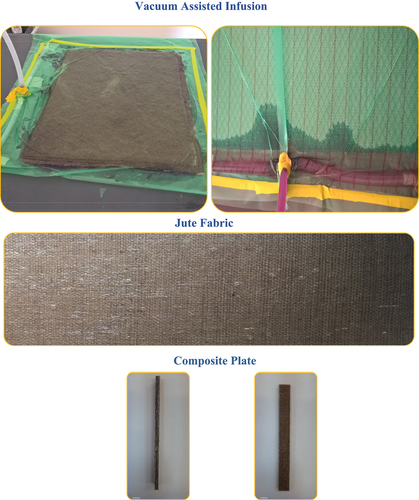
The jute woven fabric used as the test material in the study weighs 320 g/m2 and has 8 weft and 9 warp density. MGS RIM135 epoxy resin and RIMH135 hardener were chosen as matrix material. This epoxy resin used is widely used in aviation, automotive, marine, aerospace, wind propellers and defense sectors in the world in advanced composite parts manufacturing. MGS RIM135 system, which can be cured at room temperature, was prepared by adding 2:1 hardener according to the mixing ratio recommended by the manufacturer. The epoxy resin used in the production of the composite material has a density of 1,1–1,23 g/cm3 and the epoxy hardener has a density of 1–1,02 g/cm3, and their viscosity is 1000–1500 mPas. Operating temperatures are −60°C/+50°C. Moisture-free woven jute fabrics were subjected to NaOH surface modification by cutting 300 mm x 600 mm with 0°/90° orientation angles. Jute fabrics were kept in 10% NaOH solution for 6 hours.
The deconcentrated fabrics were dried in open air for 24 hours. Composite plate with 12 layers of jute was produced using vacuum assisted infusion method (). These composites with a thickness of 10 mm were cut in dimensions of 20 mm x 250 mm for the tensile tests and 30 mm x 250 mm for the drilling tests. The tensile strength of the produced jute reinforced composite was carried out using a Shimadzu brand Autograph AG-X model universal test device with a load capacity of 100 kN, at a tensile speed of 1 mm/min, and the maximum tensile force obtained was 8484 N.
Figure 2. Jute composite plates fabrication process.
Drilling process
Jute fiber reinforced material was drilled using Brother brand Speedio S500×1 model CNC Vertical Machining Center. The machining center has a maximum speed of 10,000 rpm and a spindle power of 9.5 kW. The experiments were carried out using HSS drills with a tip angle of 118° and a diameter of 7.5 mm. In the drilling process, 3 different feed and speed values were used (). The parameters are determined according to the capacity of the machine and the optimum time-quality intervals used extensively in the industry. Composite plates are fixed by being clamped between the jaws of a vise in a balanced manner. Each experiment was repeated three times. The experimental set was planned using the L9 orthogonal full factorial structure.
Table 1. Drilling parameters.
Three holes were drilled for each changed parameter set. ANOVA analysis was used to examine the effect of drilling parameters on thrust force, vibration, roughness, delamination. Analyses were made in Minitab package program.
Force and vibration measurement
Kistler 9257B type 8-component piezo-electric dynamometer was used to determine the cutting thrust force values. The dynamometer plate is positioned under the workpiece. The plate, which is sensitive to the pushing force in the z direction, sends a force signal with a sensitivity of −3.7 pC/N (picocoulomb/Newton). Kistler 5070 multichannel amplifier was used to convert the signals obtained from the dynamometer into data. The processing of the obtained signals was carried out with the Kistler Dynoware 2825A-02-01 software.
Kistler 8702B500 type accelerometer with low impedance was used for vibration measurements. The technical features of the accelerometer are shown in . Accelerometer, NI9234 DAQ card and computer connection is provided. LabVIEW package program was used to take the vibration data generated during the experiments into the computer environment.
Table 2. Technical characteristics of the accelerometer used in the experiment.
Delamination measurement
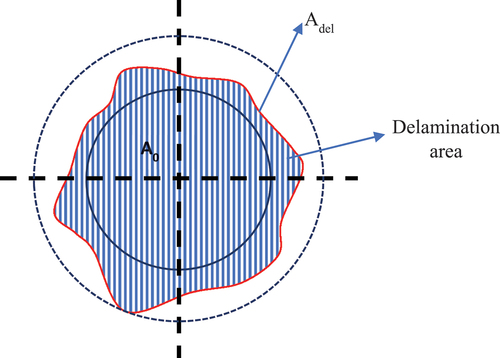
Delamination is one of the types of damage that occurs in drilling of fiber reinforced plastic composites. This damage has a negative effect on the mechanical properties of composite materials. It is formed at the hole entrance and exit during the drilling of composite materials. The size of this damage is measured by the delamination factor (). The delamination factor (Fd) is found by the ratio of the delamination area (Adel) to the hole area (Ao) (Equation x1). When Fd = 1, the delamination factor is at its ideal value, which means that the delamination area is equal to the hole area, in other words, the delamination is 0 (zero).
Figure 3. Delamination factor calculation.
For delamination measurement, images were taken from the hole inlets and outlets of the part with a Euromax Stereo microscope. The delamination area was measured using image processing methods.
Surface roughness and temperature
The surface roughness of the hole surface was measured with the Mitutoyo SJ210 device in drilling of jute reinforced composites. The instrument probe is 6 mm in diameter and each measurement was made at a sampling length of 0.25 mm. In order to be able to measure, the samples were cut along the bore axis. In order to ensure experimental stability, 3 measurements were taken from each hole and the average of the values was used.
Images were taken from the inner surfaces of the holes with a Euromax microscope, and the change of the layers according to the drilling parameters was examined.
The temperature reaching the upper part of the composite material during drilling was measured with the thermal camera Testo 868 and its internal software.
Result and discussion
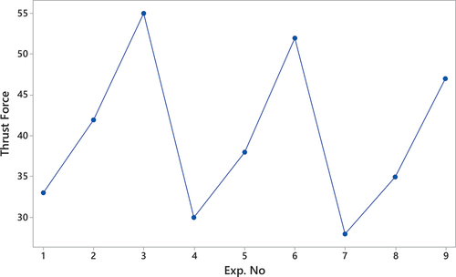
Delamination factor and surface roughness, which determine the quality of the hole in jute material, depend on the pushing thrust force and vibration generated during the drilling process (Kudus et al., Citation2022; John and Thirumalai Kumaran Citation2020). Therefore, it is necessary to examine the machining parameters that cause the thrust force and vibration. In , thrust force, vibration, delamination factor and roughness values are given for each test.
Table 3. Drilling test results.
Effect of drilling parameters on thrust force and vibration
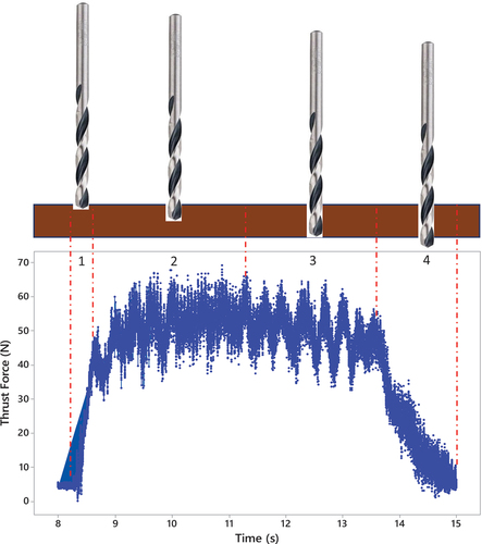
The thrust force variation in the drilling process is defined by dividing it into 4 regions. The thrust force diagram of the drilling process at the lowest feed rate and speed (0.05 mm/rev-3000 rpm) is shown in . In region 1 of the diagram, the thrust force increases rapidly as the drill bit makes the first contact with the workpiece. At the beginning of zone 2, the cutting edges of the drill come into full contact with the workpiece. After this stage, the thrust force shows a balanced course at its maximum value. This situation continues until the midpoint of the workpiece, and in the transition from the middle point to the lower region (3rd region), the thrust force decreases and proceeds in a new balance. The reason for the decrease in the thrust force in the 3rd region is the decrease in the amount of material in front of the drill. In the 4th region, the cutting edges of the drill come out of the workpiece, rapidly throwing the material in front of it, and the thrust force decreases at the same speed. The tool performs continuous drilling when entering the workpiece, while the drilling process slows down with the decrease of the material in front of the tool at the exit. Therefore, the rate of decrease of the thrust force in the 4th region is slower than the increase rate of the thrust force in the 1st region.
Figure 4. Thrust force diagram in drilling.
The basic parameters affecting the thrust force and vibration change are the feed and speed values. Drilling parameters affect the thrust force and vibration depending on the amount of chip that the drill contacts and cuts in each revolution according to the thickness of the workpiece. In , the thrust force change graph according to the feed and speed is presented. Gray dots show the change in thrust force at the same feed and speed values. The blue dots show the thrust force change according to the feed and the increase of the speed. As the feed rate increases at the same thrust force value, the thrust force increases (Machado et al. Citation2021). For 3000 rpm, the thrust force value is respectively 33,42,55 N at 0.05,0.10,0.15 mm/rev feed. In the other speed values, the situation increased in the same way. With the increase in feed, the drill dives further into the workpiece with each speed and tries to cut a thicker chip. This increases the thrust force at the cutting edge. As the speed increases at the same feed rate, the thrust force decreases (John and Thirumalai Kumaran, Citation2020). For 0.05 mm/rev feed, the thrust force values were respectively 33,30,28 N at 3000,5000,7000 rpm. Similar results were obtained at other speed values. The increase in the speed of the drill per unit time ensures that the material of less thickness encounters the resistance in each revolution of the same advance. This has the effect of reducing the thrust force ().
Figure 5. Change in thrust force with respect to feed and revolution.
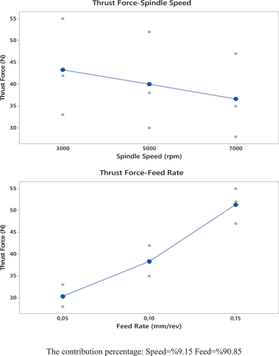
Figure 6. Thrust force distribution graph.
When the ANOVA analysis is examined, the effect of speed and advancement on the thrust force becomes significant with p < .05 (). According to the experimental parameters, the effect of the feed on the thrust force is higher than the speed value (Tsao Citation2008). The regression coefficient (R2) of the model is measured as 0.9787. This value shows that the speed and feed are in high agreement with the thrust force.
Table 4. ANOVA results of the thrust force.
shows the effect of the change in drilling parameters on vibration. In general, as the thrust force increases, the vibration is expected to increase (Çelik, Kilickap, and İ̇mran Kilickap Citation2019). However, in the drilling of composite materials, factors such as the size of the transitions between the layers and the flexibility of the material cause the vibration to decrease or fluctuate with the increase in thrust force (R. John et al. Citation2021). This situation is clearly seen in the ANOVA analysis (). The regression coefficient (R2) of the model is measured as 0.2329, which indicates that the effect of drilling parameters on vibration is unstable. The effect of speed and feed on vibration is meaningless on its own as it does not meet the p < .05 condition. However, the vibration increasing effect rate of the feed is higher than the rate of the speed reducing effect. This situation is observed in when the feed increases from 0.10 mm/rev to 0.15 mm/rev. For this reason, the effect of speed in each period was evaluated independently.
Figure 7. Variation in vibration with feed and speed.
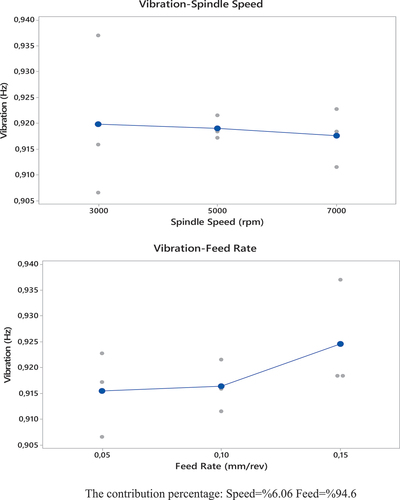
Table 5. ANOVA results of vibration.
The increase in the thrust force due to the advance at low speeds increased the vibration. With the advancement at 3000 rpm, the vibration values were respectively 0.9066,0.9159,0.9370. Vibration increases up to a certain point with the increase in feed rate at higher speed and then decreases. With the increase in feed, the drill presses the material more strongly and the flexible material vibrates less. In addition, as the speed increases, the tool heats up more, and the parts that break off from the material become irregular and fluctuate the vibration value. When the experiments were examined in general, the decrease in the thrust force decreased the average vibration (). The highest vibration and thrust force (0.9370 Hz-55 N) are observed in the 3rd experiment, at the lowest speed (3000 rpm) and highest feed (0.15 mm/rev) values.
Analysis of hole roughness
The influence of drilling parameters on the surface roughness of the hole can be seen in . The main factors that cause surface roughness in drilling are vibration and temperature (Choudhury, Mridusmita, and Debnath Citation2018). When the graph is examined, it is seen that the roughness tends to increase and decrease similar to vibration. The average roughness value decreased with the increase of the speed between 3000,7000 rpm. Increasing the speed has a reducing effect on vibration at low feed rates. However, increasing the feed rate increased both the vibration and the temperature, thus increasing the average roughness value. The highest roughness value (5.020 µm), the lowest speed (3000 rpm) and the highest feed (0.15 mm/rev) were seen.
Figure 8. Effect of feed and speed on surface roughness.
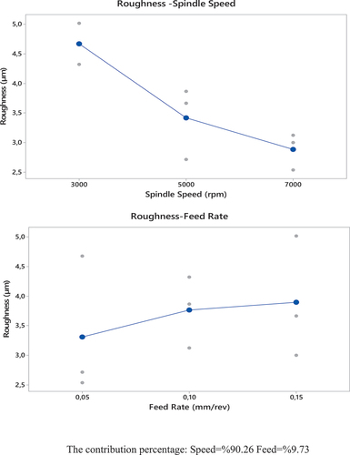
When the ANOVA results are examined, it is seen that the effect of the speed value on the roughness is higher . The regression coefficient (R2) is measured as 0.8491. The effect of advancement on roughness is insignificant compared to the effect of speed (p = .120 > 0.05).
Table 6. Drilling parameters-Roughness ANOVA results.
Increasing the speed in the drilling process increases the number of times the tool contacts the workpiece per unit time. As the feed rate increases, the thrust force applied by the tool to the workpiece increases. Both situations increase the temperature at the contact point ().
Figure 9. Effect of feed and speed on temperature.
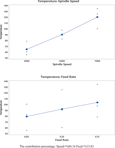
The levels of the effects of the speed and feed values on the temperature are shown in the ANOVA table (). The regression coefficient (R2) of the model is 0.9693 and the drilling parameters have a high correlation with the temperature. Accordingly, both parameters are effective on temperature with p < .05 value. Because pspeed = 0.000<pfeed = 0.002, the increase in speed has a greater effect on the temperature than the feed.
Table 7. Drilling parameters-Temperature ANOVA results.
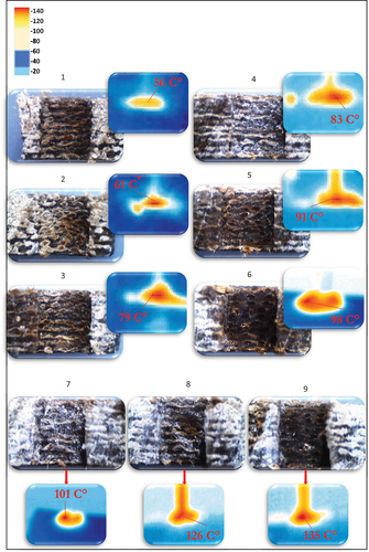
The effect of temperature on the drilling of composite materials is evident in the layers of the hole microstructure. The temperature increasing with the effect of the drilling parameters, decreases the strength of the binder material by showing a thermal effect between the layers (Shankar et al. Citation2022). Therefore, in the transition between layers, the cutting edges of the drill cut irregular chips. As mentioned in the previous section, this changes the vibration and roughness distribution in a thrust force-independent manner.
When is examined, it is seen that the layers on the inner surface of the hole change according to the experiments. From the 1st experiment to the 9th experiment, the temperature increased with the increase in the feed and speed values and the clarity of the hole inner layer transitions decreased. The increasing temperature deteriorated the rigidity of the binder material, melted and it filled the lower interlayers while creating large voids in the melted areas (Ismail et al. Citation2016). After 7000 rpm, irregular chip breaks are observed, especially in the middle parts of the inner surface. This also explains the irregularity in vibration. With the increase in speed in the same period, the transition between layers has become more evident. As the speed goes from the 1st experiment to the 3rd experiment, the thrust force increases and the layers get closer to each other.
Figure 10. Hole inner layers and temperature variation.
Delamination analysis
The delamination factor of the hole entrances and exits was calculated by determining the delamination area using the image processing method (). As the drill enters the workpiece, the increased thrust force from the first point of contact makes a more unstable cut until the drill stabilizes. For this reason, irregular fragment ruptures occur around the entrance area (Zhang and Xiaojie Citation2021). The layer that thins from the middle of the workpiece toward the exit, breaks off with the effect of the thrust force and causes delamination around the exit area.
Figure 11. Determination of the delamination area by image processing method.
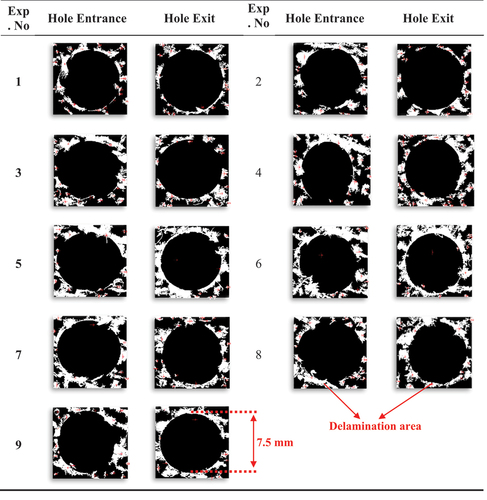
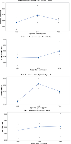
The variation of the delamination in the inlet and outlet regions of the workpiece according to the machining parameters is shown in . For both regions, delamination increased with the increase of the speed from 3000 rpm to 5000 rpm and decreased with the increase from 5000 rpm to 7000 rpm. Delamination at 7000 rpm is higher than at 3000 rpm. Irregular breaks occur around the hole during the entry of the drill into the workpiece, until the cutting edges come into full contact with the edge of the hole. This situation increases with the increase of the linear velocity of the cutting edges. As the drill moves into the part, it makes more stable cutting. The main reason why the delamination rises up to 5000 rpm and decreases again at 7000 rpm is that the effect of the speed on the cutting is higher than the effect of the feed on the cutting. 7000 rpm speed reduces the effect of advancement on the thrust force, thus reducing delamination (Adda et al. Citation2021). Delamination increased as the feed increased in both the entry and exit zone. The increase in feed for the entry zone causes the drill to hit the workpiece faster and cut irregularly. In the exit region, the thin layer is thrusted without shearing, causing the weak parts on the edge to break. Another factor affecting the delamination area in the exit region is temperature. The drill, which reaches high temperature, softens the thin and weak fibers on the hole edges and causes them to break. The highest delamination in the inlet and outlet regions was seen at 5000 rpm and 0.15 mm/rev feed rates.
Figure 12. Variation in the delamination coefficient the processing parameters.
Conclusion
This study focused on investigating the effects of drilling parameters and conditions on hole quality when drilling jute fiber reinforced composite materials. The main results and contributions of the study are as follows;
- Increase in feed at constant speed increases thrust force, vibration and temperature. Especially with the increase in vibration and temperature, the irregularity on the cutting surface of the drill increases the internal roughness of the hole. Likewise, the increase in the thrust force of the feed and the removal of the chip from the material by breaking, not by cutting, with increasing temperature increases the delamination at the entrance and exit of the hole. In the applied parameters, the effect of the speed on the roughness is more than the effect of the feed.
- With the increase in the speed, the thrust force and vibration decrease and the temperature increases. Reduction of thrust force and vibration reduces roughness. Here, the negative effect of the temperature increase on the roughness is statistically insignificant besides the positive effect of the decrease in vibration. The amount of delamination at the hole entrance and exit first increases and then decreases with the increase of the speed. In the applied drilling parameters, after the speed value reaches a certain point, it causes the delamination to decrease by breaking the increasing effect of the feed on the delamination.
- The effect of feed and speed on thrust force was calculated as 97.87%. The effect of the feed on the thrust force (90.85%) is far greater than the effect of the speed (9.15%). The effect of drilling parameters on vibration is statistically insignificant due to the different spread behavior in the layers of the composite material (R2 = 0.2329). However, the effect of feed on vibration (94.6%) is greater than the effect of speed (6.06%). The temperature is affected by 96.93% of the drilling parameters and the speed is 84.16% and the feed is 15.83%. The roughness effect depending on the drilling parameters is measured as 84.91%. The effect of speed on roughness (90.26%) is greater than the effect of advancement (9.73%).
In the study, it is expected to contribute to the parameter selection stage in high-speed drilling of composite materials. However, it will be a guide for studies examining the effect of processing conditions on quality in drilling natural composites.
Conflicting interests
The authors have no relevant financial or non-financial interests to disclose.
Disclosure statement
No potential conflict of interest was reported by the author(s).
Additional information
Funding
References
- Abilash, N., and M. Sivapragash. 2016. Optimizing the Delamination Failure in Bamboo Fiber Reinforced Polyester Composite. Journal of King Saud University - Engineering Sciences 28 (1):92–20. King Saud University. doi:10.1016/J.JKSUES.2013.09.004.
- Adda, B., A. Belaadi, M. Boumaaza, and M. Bourchak. 2021. Experimental Investigation and Optimization of Delamination Factors in the Drilling of Jute Fiber–Reinforced Polymer Biocomposites with Multiple Estimators. International Journal of Advanced Manufacturing Technology 116 (9–10):2885–907. Springer Science and Business Media Deutschland GmbH. doi:10.1007/S00170-021-07628-9.
- Belaadi, A., M. Boumaaza, S. Amroune, and M. Bourchak. 2020. Mechanical Characterization and Optimization of Delamination Factor in Drilling Bidirectional Jute Fibre-Reinforced Polymer Biocomposites. The International Journal, and Undefined 2020 111 (7–8):2073–94. Springer Springer Science and Business Media Deutschland GmbH. doi:10.1007/s00170-020-06217-6.
- Çelik, Y. H., E. Kilickap, and A. İ̇mran Kilickap. 2019. An Experimental Study on Milling of Natural Fiber (Jute)- Reinforced Polymer Composites. Journal of Composite Materials 53 (22):3127–37. SAGE Publications Ltd. doi:10.1177/0021998319826373.
- Choudhury, R., M. S. S. Mridusmita, and K. Debnath. 2018, August. Experimental Investigations on Drilling of Lignocellulosic Fiber Reinforced Composite Laminates. ( Elsevier Ltd) Journal of Manufacturing Processes 34:51–61. doi: 10.1016/J.JMAPRO.2018.05.032.
- Choudhury, M. R., M. S. Srinivas, and K. Debnath. 2022. ‘Experimental Investigations on Drilling of Lignocellulosic Fiber Reinforced Composite Laminates’. Journal of Manufacturing and undefined 2018 Elsevier Accessed September 16 https://www.sciencedirect.com/science/article/pii/S1526612518306066.
- Ellenberger, A., M. Luiz Polli, E. Azevedo, and C. R. P. de Paula. 2022. Drilling of Natural Fiber-Reinforced Based Polyurethane Foam Composite. Journal of Composite Materials 56 (6):899–909. SAGE Publications Ltd. doi:10.1177/00219983211059581.
- Gharde, S., and B. Kandasubramanian. 2019. Mechanothermal and Chemical Recycling Methodologies for the Fibre Reinforced Plastic (FRP). Environmental Technology & Innovation 14 (May):100311. Elsevier. doi:10.1016/J.ETI.2019.01.005.
- Ismail, S. O., H. N. Dhakal, I. Popov, and J. Beaugrand. 2016. ‘Comprehensive Study on Machinability of Sustainable and Conventional Fibre Reinforced Polymer Composites’. Engineering Science and Technology, an International Journal 19 (4):2043–52. Elsevier Accessed September 16. doi:10.1016/j.jestch.2016.07.010.
- Jayabal, S., U. Natarajan, and U. Sekar. 2011. Regression Modeling and Optimization of Machinability Behavior of Glass-Coir-Polyester Hybrid Composite Using Factorial Design Methodology. International Journal of Advanced Manufacturing Technology 55 (1–4):263–73. doi:10.1007/S00170-010-3030-7.
- John, R., R. Lin, K. Jayaraman, and D. Bhattacharyya. 2021. Effects of Machining Parameters on Surface Quality of Composites Reinforced with Natural Fibers. Materials and Manufacturing Processes 36 (1):73–83. Bellwether Publishing, Ltd. doi:10.1080/10426914.2020.1813896.
- John, K. M., and S. Thirumalai Kumaran. 2020. A Feasible Strategy to Produce Quality Holes Using Temperature-Assisted Drilling on CFRP. International Journal of Advanced Manufacturing Technology 110 (11–12):3113–27. Springer Science and Business Media Deutschland GmbH. doi:10.1007/S00170-020-06089-W.
- Khan, T., M. T. B. Hameed Sultan, and A. H. Ariffin. 2018. The Challenges of Natural Fiber in Manufacturing, Material Selection, and Technology Application: A Review. Journal of Reinforced Plastics and Composites 37 (11):770–79. Journals.Sagepub.Com SAGE Publications Ltd. doi:10.1177/0731684418756762.
- Kiran, M., M. J. Nagamadhu, K. Karthikeyan, and M. Shariff. 2019. ‘Study the Impact of Drilling Process Parameters on Natural Fiber Reinforced Chaired Epoxy Composites’. Materials Today: Proceedings 24. Elsevier Ltd: 2204–18. doi:10.1016/J.MATPR.2020.03.678.
- Kudus, A., M. Helmi, and M. Maran Ratnam. 2022. Image Processing Method for Delamination and Fiber Pull-out Assessment during Drilling of Natural Fiber Composites. Journal of Reinforced Plastics and Composites 41 (7–8):309–27. SAGE Publications Ltd. doi:10.1177/07316844211051734.
- Kumar, A. M., R. Rajasekar, P. Manoj Kumar, R. Parameshwaran, A. Karthick, V. Mohanavel, T. Sakthi, M. Muhibbullah, and J. Xu. 2022. ‘Investigation of Drilling Process Parameters of Palmyra Based Composite’. Advances in Materials Science and Engineering 2021:1–9. Hindawi.Com Accessed September 16. doi:10.1155/2021/4222344.
- Machado, C. M., D. Silva, C. Vidal, B. Soares, and J. Pamies Teixeira. 2021. A New Approach to Assess Delamination in Drilling Carbon Fibre-Reinforced Epoxy Composite Materials. International Journal of Advanced Manufacturing Technology 112 (11–12):3389–98. Springer Science and Business Media Deutschland GmbH. doi:10.1007/S00170-021-06636-Z.
- Malik, K., F. Ahmad, and E. Gunister. 2021. Drilling Performance of Natural Fiber Reinforced Polymer Composites: A Review. Journal of Natural Fibers 19 (12):4761–79. doi:10.1080/15440478.2020.1870624.
- Mohan Kumar, A., R. Rajasekar, P. Manoj Kumar, R. Parameshwaran, A. Karthick, M. Muhibbullah, and J. Xu. 2021. Comparative Analysis of Drilling Behaviour of Synthetic and Natural Fiber-Based Composites. Advances in Materials Science and Engineering 2021 2021:1–13. January Hindawi Limited. doi:10.1155/2021/9019334.
- Nasir, A. A. A., A. I. Azmi, and A. N. M. Khalil. 2022. ‘Measurement and Optimisation of Residual Tensile Strength and Delamination Damage of Drilled Flax Fibre Reinforced Composites’. Elsevier. Accessed September 16. https://www.sciencedirect.com/science/article/pii/S0263224115003942.
- Rezghi Maleki, H., M. Hamedi, M. Kubouchi, and Y. Arao. 2019. Experimental Investigation on Drilling of Natural Flax Fiber-Reinforced Composites. Materials and Manufacturing Processes 34 (3):283–92. Taylor and Francis Inc. doi:10.1080/10426914.2018.1532584.
- Shadrach Jeya Sekaran, A., and K. Palani Kumar. 2019. ‘Study on Drilling of Woven Sisal and Aloevera Natural Fibre Polymer Composite’. Materials Today: Proceedings 16. Elsevier Ltd: 640–46. doi:10.1016/J.MATPR.2019.05.140.
- Shankar, V. K., S. Sehgal, N. Mahadevappa, V. K. Shankar, and R. Upadhya. 2022. Study the Impact of Drilling Process Parameters on Natural Fiber Reinforced Herringbone Epoxy Composites. Accessed September 19. doi:10.18280/acsm.440506.
- Tsao, C. C. 2008. Thrust Force and Delamination of Core-Saw Drill during Drilling of Carbon Fiber Reinforced Plastics (CFRP). International Journal of Advanced Manufacturing Technology 37 (1–2):23–28. doi:10.1007/S00170-007-0963-6.
- Xu, J., A. Mkaddem, and M. E. Mansori. 2016. Recent Advances in Drilling Hybrid FRP/Ti Composite: A State-of-the-Art Review. Composite Structures 135:316–38. Elsevier Accessed September 16. doi:10.1016/j.compstruct.2015.09.028.
- Zhang, Y., and X. Xiaojie. 2021. Predicting the Delamination Factor in Carbon Fibre Reinforced Plastic Composites during Drilling through the Gaussian Process Regression. Journal of Composite Materials 55 (15):2061–68. SAGE Publications Ltd. doi:10.1177/0021998320984245.