
 ?Mathematical formulae have been encoded as MathML and are displayed in this HTML version using MathJax in order to improve their display. Uncheck the box to turn MathJax off. This feature requires Javascript. Click on a formula to zoom.
ABSTRACT
Cocolog groynes are new form of soft stabilization method, which can be used for restoration of river meanders. After an extensive literature review, it was observed that conventional impermeable groynes behave in a different manner compared to the cocolog groynes which are permeable in nature. Hence, the objective of the present study was to analyze the effect of significant geometrical and hydraulic properties of cocolog groynes on scour and flow patterns in meandering channels. The experimental studies were conducted in a scaled physical model of meandering channel with series of cocolog groynes installed at aspect ratios between 2 and 4, density ratios between 0.12 and 0.18, relative lengths between 0.14 and 0.2 and for orientation angles from 30º to 150º. The desirable range of these parameters for cocolog groynes in meandering channels were obtained as 2.5 to 3.0, 0.14 to 0.16, 0.16 to 0.18 and <90º, respectively, after analyzing the bed scour and dimensionless mean velocity in both streamwise and transverse directions. The study provides an appropriate layout of an eco-friendly soft river bank stabilization technique, which not only promotes vegetation but also restores the river banks.
摘要
椰子坝是一种新型的软稳定方法,可用于河曲的修复. 在广泛的文献综述之后,观察到传统的不透水丁坝与本质上可渗透的椰子树丁坝的表现方式不同. 因此,本研究的目的是分析椰子坝的重要几何和水力特性对弯曲河道冲刷和水流模式的影响. 实验研究是在曲流河道的缩放物理模型中进行的,该模型中安装了一系列椰壳坝,其纵横比为2至4,密度比为0.12至0.18,相对长度为0.14至0.2,方位角为30º至150º. 在对河床冲刷和无因次平均流速进行分析后,曲流河道中椰子坝的理想参数范围分别为2.5至3.0、0.14至0.16、0.16至0.18和<90º. 该研究提供了一种生态友好的软河岸稳定技术的合理布局,该技术不仅可以促进植被,还可以恢复河岸.
Introduction
Scouring and bank erosion are important problems in natural rivers. Groynes, or spurs, are extensively used in natural rivers to safeguard against bank erosion and to enhance morphological and ecological diversities (Zhang, Nakagawa, and Muramoto Citation2012). Because of additional factors, such as bend geometry, helical flow in the bend, transverse slope of bed, and angle of attack of flow on the groyne structure, the scour pattern around groyne structures in a meander bend is more complex than in a straight channel. Numerous studies have been carried out on the different aspects of groynes using experimental flumes. Most studies have been carried out on straight flumes (Sukhodolov, Uijttewaal, and Engelhardt Citation2002; Yeo, K, and Kim Citation2005) and only a limited number of studies have been conducted in river bends (Fazli, Ghodsian, and Neyshabouri Citation2008; Przedwojski Citation1995; Sharma and Mohapatra Citation2012). At the groyne tips, flow separation takes place, leading to scouring and flow reduction in the recirculation zone, which encourages the deposition of fine sediments (Sukhodolov, Uijttewaal, and Engelhardt Citation2002).
Several researchers also analyzed the flow characteristics and scouring around the groynes of various permeabilities in straight channels (Gu, Akahori, and Ikeda Citation2011; Kang et al. Citation2011; Mahmoud et al. Citation2013; Mostafa et al. Citation2019; Yeo, K, and Kim Citation2005). The extent of the scour hole around groynes is affected by the location of the groyne in the bend, relative length, orientation angle, and permeability of groynes, aspect ratio of the groyne series, and Froude number (Fazli, Ghodsian, and Neyshabouri Citation2008; Gu, Akahori, and Ikeda Citation2011; Kang et al. Citation2011). Aspect ratio, defined as the ratio of spacing between groynes (S) and length of groyne (L), influences the bed formation and velocity patterns in groyne fields (Gu, Akahori, and Ikeda Citation2011). For straight channels, the separation length varies with the permeability, and when the distance between the permeable dikes increases, the dimensions of vortexes also increase (Kang et al. Citation2011). Permeable groynes allow water to flow through them and reduce the velocity and eddies in the groyne fields compared to impermeable groynes and hence, reduce local scour. Cocologs are erosion control logs made out of coir geotextiles filled with coir fibers and are extensively used in various countries for soil erosion control on slopes. Cocologs used as groynes in the Manimala River basin effectively reduce velocity between groynes by promoting deposition, according to Anil et al. (Citation2011). Kang et al. (Citation2011) observed that the local scouring around the tip of the groyne was significantly reduced when permeable pile groynes are used, and the reduction in scouring was due to the effect of permeability. The relative length of groynes (ratio of length of groynes to the bed width of the channel) should be less than half the floodplain width because a large relative length leads to more scouring and deposition around impermeable groynes by the generation of eddies and roller zones downstream (Ahmed, Hasan, and Tanaka Citation2010). The orientation angle of groynes affects the scour depth and silting height in channels and the least and maximum erosion of the bed around spur dikes with 90º and 135º angles, respectively (Kuhnle, Alonso, and Shields Citation2002). The flow will be directed toward the groynes at a 135º angle, causing greater scour, whereas the flow will be shifted away from the groynes region, reducing scour at a 90º angle. A laboratory study conducted by Mostafa et al. (Citation2019) on single permeable groynes observed a 30% reduction in maximum velocity and a 22% reduction in tip velocity by increasing the groyne permeability to 60%. From the literature, it was observed that the permeability, aspect ratio, orientation, and length of the groynes significantly affect the flow and scour pattern around groynes. Most of the experimental studies on scour around groynes were available for impermeable structures in straight channels and limited information is available for scour estimation around permeable groynes using natural materials in meandering channels. Only limited exploration has reported on scouring around permeable groynes using bioengineering techniques.
The use of natural geotextiles, such as cocologs may be preferred as they are less expensive and are environmental friendly due to their biodegradability. A field study was conducted by Anil et al. (Citation2011) using cocolog groynes placed at 45º angle in a curved natural channel in Southern Kerala, India. The study reported that cocolog groynes reduced river bank erosion by depositing soil particles along the river banks. After 30 months, the cocologs biodegraded and the dense vegetation was seen around groynes that prevented further erosion of the bank completely. However, no studies were conducted to analyze the effect of variations of governing parameters of cocolog groynes on scour-deposition patterns. Studies conducted on the field by Anil et al. (Citation2011) encouraged to carry out more detailed analysis on the effect of geometrical and hydraulic parameters of cocologs groynes in meandering channel. Further cocologs can bear the impact of water along the curves and make the slope vegetated. They are manufactured from eco-friendly materials like coir fiber in the local coir societies in southern Kerala. This increases the employability of women in rural areas. Hence in the present study, the suitability of using eco-friendly cocolog (permeable) groynes at meanders was investigated experimentally. The scouring and flow around groynes of different permeability under different aspect ratios and orientation angles were studied in detail and the results were compared with those of impermeable groynes. It is expected that the results of the present study will lead to the development of a new design guidelines for cocolog groynes in natural channels that is not available now.
Dimensional analysis
The various parameters that influence the sediment movement and flow around cocolog groynes in channels were considered for detailed model analysis. Hence, the scour depth (ds) around groyne fields in the channel bends depends on water depth (), channel width (B), viscosity (μ), approaching velocity (uo), critical velocity (vc), mean particle size (d50), acceleration due to gravity (g), density of water (ρw), density of sediment (ρs), density of cocolog groynes (ρg), orientation angle (θ), width of the groynes (w), projected length of the groyne (L), spacing between the groynes (S), radius of the bend (Rc), and bed slope of the channel (S0). It was found from previous studies (Fazli, Ghodsian, and Neyshabouri Citation2008; Gu, Akahori, and Ikeda Citation2011; Kang et al. Citation2011; Mahmoud et al. Citation2013) that an increase in the parameters, such as water depth, velocity of flow, projected length, and spacing of groynes, increases the local scour near the groyne structures, whereas permeability of groynes has an opposite effect and the effect of other parameters on scour and turbulence are still not explored.
The relationship between these parameters is given as:
Dimensional analysis was performed to obtain nondimensional parameters and all experiments were planned based on the results obtained. The scour depth ratio (Sr) can be represented as:
Eliminating the constant variables in the experiment, the equation (ii) can be simplified as
Hence the scour depth ratio varies with aspect ratio
, relative length
, orientation angle of groynes (
) and the density ratio
.
Methodology
Preparation of cocolog groyne models
The groyne models were prepared with a scale ratio of 1:20 using cocologs. Cocologs are commercially available with diameters ranging from 0.3 m to 0.6 m and lengths of 3 m to 6 m. Considering a 0.6 m diameter cocolog, 0.03 m diameter models were prepared with four different densities; 120, 140, 160, and 180 kg/m3 (named CG1 to CG4). The highest and lowest density of commercially available cocologs are in the range of 140 to 160 kg/m3. Considering a lower and higher value from this range, the present range is selected. Density lower than 120 kg/m3 makes cocologs more flexible and porous, whereas making cocolog models with a density of more than 180 kg/m3 was very difficult. These cocolog models were stacked one above the other and tied together using coir yarn to form groynes. show the prototype and modeled cocolog groynes. The permeability of the cocolog mainly depends on the density of the coir fibers filled inside and follows an exponential relation proposed by Indulekha et al. (Citation2021) as shown in EquationEquation 4(4)
(4) .
Figure 1. Cocolog used as g roynes (a) Prototype (b) Model.
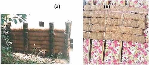
where kc is the permeability of cocologs in mm/s and ρg is the density of cocologs in kg/m3. The permeability values of the cocologs used for experimental study are shown in . Stainless steel metal plates, designated as IG1, were used for impermeable groynes.
Table 1. Properties of cocolog groynes.
Preparation of physical model of a meandering channel
Vamanapuram River, located in Southern India, was selected for the study. The critical areas of erosion and deposition of Vamanapuram river over a period of 50 years were identified by extracting the bank lines over a period of 50 years using GIS techniques (J and Indulekha Citation2016). The most affected curved portion was selected for conducting a physical model study in the laboratory. The curved channel selected has a value of 2.80, which represents a strongly curved channel (Yan, Rennie, and Mohammadian Citation2020). The curved portion of the river was scaled down to a horizontal scale ratio of 1:60 and a vertical scale ratio of 1:20 with three consecutive bends of 67° (Bend 1), 135° (Bend 2), and 67° (Bend 3) angles as shown in The cross section of the Vamanapuram river basin was scaled down by applying Froude’s similitude law. shows the photograph of the physical model constructed for laboratory study. Sediment collected from the river site having a mean diameter d50 of 0.85 mm and a geometric standard deviation of 1.82 is filled uniformly in the flume. A sediment layer of 100 mm in thickness was used in the channel to maintain the integrity of the tests. An approach channel was designed for a smooth transition of the inflow water into the meandering channel. The sediment coming out of the channel was collected in a properly designed sedimentation basin with a 600 mm drop. An automated traversing system was fabricated with an accuracy of 1 mm in both traverse and vertical directions for positioning an Acoustic Doppler Velocimeter (ADV). The variation of the bed near the groyne region was continuously monitored using three bed profile sensors during the experiments. When the temporal variation of scour depth remained constant after 2 h in the groyne region, it was assumed as flow had stabilized. Bed profile and velocity measurements were taken at specified grids along radial sections (Sections 1 to 15) as shown in , after the flow is stabilized. A straight channel section with a 2 m length was included before the first bend to ensure that flow was fully developed at the first groyne. Also, a straight portion of 2 m length was provided downstream to analyze the scour pattern immediately downstream of the last groyne.
Figure 2. Schematic diagram of the physical model set up.
Figure 3. Arrangement of groynes (a) 45º, (b) 60º (c) 90º and (d) 135º.
Experimental programme
Experiments were conducted in a curved flume representing a meandering portion of a selected river. Considering the extreme discharge conditions of Vamanapuram river, discharge was scaled down as per Froude’s model law and was fixed as 0.027 m3/s for all the experiments. A scale ratio of 1:20 was selected considering the convenience of obtaining a minimum depth for installing the velocimeter for velocity measurements and the required discharge of 0.027 m3/s for conducting experiments in the laboratory. During the test, a constant approach velocity of 0.43 m/s and a flow depth of 0.150 m were used. For the experimental flow conditions dimensionless critical tractive stress was obtained from Shield’s diagram and it showed that the particle is moving. In all the cases a subcritical flow with Froude number of 0.42 was maintained and the Reynolds number of 5.6 × 10⁴ was maintained that represents a fully developed turbulent flow. The critical tractive stress value in the current experiments is 0.58 N/m2. Based on the erosion deposition pattern for tests without groynes, groyne locations were determined and groyne numbers were fixed as four numbers at Bend 1 and six numbers at Bend 2. For the experiment, various types of groynes were used – impermeable metal groynes and permeable cocolog groynes with different permeabilities. IS 8408 (Citation1994), specially published for the planning and design of groynes in alluvial rivers, was used as a guide for fixing the dimensions of the cocolog groynes in the preliminary stage. In each experiment, the effect of change of various parameters like relative length , orientation angle (θ), permeability of the groynes, and aspect ratio (Sr =
) were analyzed. Orientation angles of 30º, 45º, 60º, 90º, 120º, 135º, and 150º were selected for analyzing the effect of orientation.
The experiments were conducted in four different steps, and the summary of flow conditions and experiments is shown in respectively. In the first step, groyne models with four relative lengths, Lr = 0.2, 0.18, 0.16, and 0.14 were tested, keeping
ratio and orientation angle at 2.5° and 45° respectively. In the second step, the effect of the orientation angle of groynes was studied by varying the orientation angles as 30º, 45º, 60º, 90º, 120º,135º, and 150º using both cocolog and impermeable groynes. Then, in the third step, the influence of aspect ratio of the groynes was analyzed by conducting experiments on various aspect ratios using cocolog groynes of different permeability (named as CG1, CG2, CG3, CG4) and metal groynes (IG1) as shown in . Each test run was carried out for a duration of 4 h. After each experiment, the bed-level readings were taken at predefined grid points using Leica DISTO pro 4 and analyzed for morphological change and turbulence patterns. A 16 MHz Acoustic Doppler Velocimeter (ADV) was used to measure the instantaneous velocities in x, y, and z directions at a sampling rate of 25 Hz. Around 3000 measurements were taken at each point to ensure 2000 observations after filtering. Data filtering was done with WinADV software with a filtering criterion of signal-to-noise ratio (SNR) and the Nikora-Goring despiking algorithm. All data with an SNR of 15 dB and a mean correlation of 70% were removed from the set. Normalized time-averaged velocities along longitudinal, transverse, and vertical directions
,
and
, respectively, were calculated, where u0 is the time-averaged streamwise velocity at the center of the channel at the upstream end. It is difficult to accurately estimate the volume of scour in the groyne fields. The percentage of eroded volume due to similar structures has been measured in a few studies (Hemmati and Daraby, Citation2019). Hence, the present study also concentrated on the measurement of eroded volume, which was calculated from Sections 2 to 14 with the help of surfer software, and the same was compared for different permeabilities, orientations, and
ratios. Surfer takes randomly spaced XYZ data and uses it to create a regularly spaced grid file, composed of grid nodes. Each grid node is located at a particular XY location and has a “z” value associated with it. Contour maps are prepared by interpolating the z values by interpolation techniques. In the present study, the erosion was quantified using the parameters scour depth ratio (ds/hw), percentage eroded volume (expressed as the percentage of the total volume of sediment), cross-sectional changes, and extent of scour holes.
Table 2. Experiment flow conditions.
Table 3. Summary of experiments.
Results and discussion
To identify the areas of erosion and deposition, experiments were conducted without any protection initially. Then, a sequence of experiments was carried out for cocolog impermeable groynes by changing the relative length (Lr), orientation angle, aspect ratio () and densities of cocolog groynes. The bed-level measurements from the experiments were analyzed using Surfer software by preparing bed contour maps. Mean flow, maximum scour depth, and eroded volume within the controlled volume were calculated and compared to arrive at suitable recommendations.
Effect of relative length of groyne
As per IS 8408 (Citation1994), the maximum projection length of the groyne should not exceed one-fifth of the bottom width of the channel, i.e., the relative length should be less than 0.20. The experiments were carried out with cocolog groynes (CG2) of different relative lengths of 0.14, 0.16, 0.18, and 0.20 for a constant ratio of 2.5 and an orientation angle of 45º.
Variation in mean flow
Normalized time averaged mean velocities in all directions at Section 8 for different relative lengths (Lr) are shown in ). The is found to have an increasing trend with increase in the relative length. It is observed that
value is 1.07 for Lr = 0.14 which increased to 1.34 for Lr = 0.2. As the relative length increases by 15%, 29% and 43%, the
increases by 10%, 21%, and 25%, respectively. In the transverse direction, the
increases in the negative direction with increase in Lr value. It was observed that for 43% increase in Lr value, the
value increased by 33% in the transverse direction. In the vertical direction, the variation of dimensional mean velocity is very small as shown in (a). Mahmoud et al. (Citation2013) also reported that as groyne length increases, the main channel velocity and tip velocity increase, which confirms the results of the present study. In meandering channels with permeable groynes, the u and v components are observed to be higher, while the w components are found almost zero from the observations. Downflow was very low in the case of permeable groynes, which has reduced the local scouring. The u and v components have a nonlinear trend due to the greater obstruction produced by the increase in the length of groynes with the added effect of the curvature of channels.
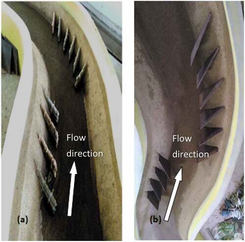
Figure 4. Photograph of physical model set up: (a) permeable groynes and (b) impermeable groyne.
Variation in scour depth
The variation of the scour depth ratio with a change in the relative length of cocolog groynes is shown in ). The scour depth ratio initially remains the same up to Lr = 0.18 and is then found to increase. For Lr = 0.16, a medium blockage of flow was occurred and the blockage increases with increase in Lr value, which in turn increases the eddies near the groynes. Hence, the scour increases for Lr > 0.16. When impermeable groynes are used, a maximum scour depth ratio of 0.35 is observed, which is in accordance with the result of Przedwojski (Citation1995). When cocolog groynes are used, the scour depth ratio is reduced to 0.26. A scour reduction of 31% is achieved for cocolog groynes compared to the impermeable ones. The form and extent of the scour holes vary with the relative length and are shown in . The maximum scour depth is observed between the first and the second groynes and the scouring extends up to the fourth groyne for larger Lr values as shown in Two separate scour holes are observed for smaller Lr = 0.14. The width of the scour hole is high for Lr = 0.2 and it decreases for smaller Lr values. Also, the outer banks of central bend are eroded in between the groyne region and downstream of groyne region for Lr = 0.14 and the banks are more protected for Lr >0.14. The spatial variations of the bed contours for various cases are included in Appendix A. The variation of the percentage eroded volume for different relative lengths is shown in . The eroded volume was high for smaller (Lr = 0.14) and larger (Lr = 0.2) Lr values. Since banks were also eroded for Lr = 0.14, bed was eroded for Lr = 0.2, the eroded volume was found high for these two Lr values. Considering the extent as well as the number of holes and eroded volume for different relative lengths, a relative length of more than 0.18 and less than 0.16 is not preferable. The desirable range of relative length was obtained as 0.16 to 0.18 from the present study. For further studies, experiments were carried out with a relative length of 0.16 based on economic considerations.
Figure 5. Scour hole formation around groynes and their extent for different relative lengths (all dimensions are in centimeters): (a) Lr = 0.2 (b) Lr = 0.18 (c) Lr = 0.16 (d) Lr = 0.14.
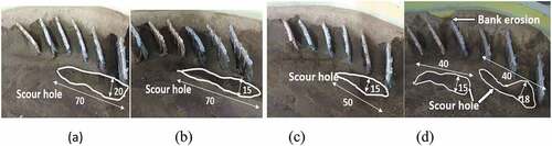
Figure 6. Variation of scour volume for different relative length.
Effect of orientation angle
For selecting the best possible value of inclination of cocolog groynes, various angles of 30º, 45º, 60º, 90º, 120º, 135º, and 150º were tested with groyne-type CG2 at = 2.5. The observations of the experiments are plotted as shown in .
Figure 7. Variation of dimensionless streamwise velocity along the lateral direction with groyne type CG2 for different orientation of groynes: (a) 30º, 45º, 60º (b) 90º, 135º, 150º.
Figure 8. Variation of ds/hw with against orientation for CG2.
Figure 9. Cross sectional profiles of Section 8 for different orientations with groyne type CG2.
Variation in mean flow
compares the lateral distribution of the normalized depth-averaged streamwise velocities at the apex of Bend 2 at
= 0.4 from the bed. As the orientation angle increases, the maximum normalizes streamwise velocity shifts farther from the outer bank. It is seen that the maximum
value is observed at the middle of the cross section for 30º and 90º and it is shifted toward the inner bank for 60º and 135º. The amplification of the streamwise velocity in the groyne field was 1.2 times the approaching flow for 45º and it increased to 1.3 and 1.4 times the approaching flow for 90º and 150º, respectively. Yarahmadi and Bejestan (Citation2016) observed the highest value of
as 1.54 for impermeable vanes mounted at an orientation angle of 30º to the outer bank in a 90º bend. The reduction in
in the present study can be attributed to the permeable nature of the groyne in the test setups. It is also observed that for angles greater than 60º, the mean stream wise velocity increased. The peak velocity observed is almost same for all orientation of permeable groynes due to the usage of the same material for all experiments, which resulted in only a slight difference in permeability values. The spatial distribution of streamwise velocity for various orientations of groyne are included in Appendix B
The normalized mean transverse velocity is negative for all angles and is the least for 45º. The negative values of
show the presence of downflow and vortices in the groyne fields. As per Kumar and Ojha (Citation2019), a dimensionless mean value
between +0.23 and −0.52 was observed in the transverse direction near impermeable L head groynes at 90º with the flow direction in straight flumes. A range of +0.09 to −0.42 was observed in the present study when cocolog groynes at an orientation of 45º was used. This shows that cocolog groynes have the capacity to reduce the velocity fluctuations in both the streamwise direction and the transverse direction. The value of
is nearer to zero for all orientations, and the result is in accordance with Kumar and Ojha (Citation2019).
Variation in scour depth
The variation of the scour depth ratio for various orientations of groynes is shown in . The value of shows an increasing trend with orientation angle up to 90º and the variation is found to be very small for angles more than 90º. For CG2, the
value is almost the same for both 45º and 60º and increases by 2.0 times for 90º, 135º, 150º, respectively, when compared with 45º. When impermeable groynes are used,
value is twice the value obtained for permeable ones for angles less than 90º, and it is 1.5 times that of cocolog groynes for angles greater than or equal to 90º. The least and the highest values of
are observed for 45º and 135º, respectively, for both cocolog and impermeable groynes. For all angles, the scour depth was less for cocolog groynes compared to impermeable ones. Studies conducted by previous researchers (Kuhnle, Alonso, and Shields Citation2002) observed a higher scour depth value for impermeable dykes compared to cocolog groynes in the present study.
shows the cross-sectional profiles for experiments with groyne-type CG2 for different orientations of groynes at section 8. The erosion was comparatively high for all angles greater than 45º. Bank material also eroded completely at angles above 90º. For 90º orientations of groynes, scouring at the tip of the groynes is maximum, eroding away the bed materials to a thickness of more than 50 mm. The same groyne material was used for all the experiments, and only the orientation angle was changed for these experiments. So the erosion depth remains almost the same for angles less than or equal to 90º, but the location of the maximum scour depth varies with orientation angle. In the groyne fields maximum erosion was observed for 135º orientation and it is about 2.5 times that obtained for 45º. In the present study for curved channels, the least erosion is observed for 45º. In meanders, an orientation angle of less than 600 is preferable for bank protection.
shows the percentage eroded volumes between Sections 2 and 14 for various ratios and orientations of different groynes. It is found that except for CG1, as permeability decreases, the volume of sediment eroded increases, indicating more erosion for lower permeability. This indicates the strong relation between eroded volume, orientation, and permeability. In all the cases, it is seen that sediment eroded volume increases with the increase in orientation angle of groynes. The least value of eroded volume of 8.33% is observed for CG2 for 45º angle. Greater volumes of the scour hole are observed for orientations greater than 60º for all types of groynes. This is in accordance with the findings by Kuhnle, Alonso, and Shields (Citation2002) wherein the highest volume of the scour hole was observed for 90° spur dikes in straight flumes. From it is observed that the bed and banks are more protected at 45º than at other orientation angles. IG1 shows higher eroded volume when compared to cocolog groynes. Investigations by Kuhnle, Alonso, and Shields (Citation2002) on various groyne orientation angles revealed that an upstream pointed groyne (θ = 45°) minimizes the amount of potential erosion of the channel bank. Permeability will be greater for less dense groynes and thus it will enable some of the incoming flow to pass through it thereby reducing the fluctuating velocity and destructive effect of flow on the bank and bed.
Figure 10. (A) Percentage eroded volume for different permeability and orientation angles (S/L = 2.5) (b) Variation of dsx/ds90 with orientation of groynes.
Effect of density ratio  of Groynes
(a) shows the variation of with
for different orientation angles. For repelling groynes (angles less than 90°), when
increases from 0.12 to 0.14, the
value decreases and slightly decreases from 3 to 2.2 and it again decreases to 1.92 for
value equal to 0.18. This means that for repelling groynes the density ratio influences much on scour depth ratio. The groynes laid perpendicular to the flow
increases as
increases. For θ > 90º,
is also found to increase with increase in density ratio. Hence repelling groynes are found suitable for meander with cocolog groynes. When the permeability increases, the eroded volume decreases. Since the eroded volume is less for CG2 and CG3 compared to others, the optimum density ratio of cocologs for river bank protection is considered as between 0.14 to 0.16. Hence, to analyze the effect of
ratio, the experiments were conducted for CG2 with a relative length of 0.16.
Figure 11. (A). Variation of ds/hw with density ratio for S/L ratio = 2.5. (b) Variation of ds/hw with S/L ratio for 45° orientation angle.
Effect of ratio (aspect ratio) of groynes
The detailed analysis on the effect of ratio for mean flow and turbulence is carried out for CG2 and IG1 for θ = 45º. (b) shows the variation of
with
for different density ratios of groynes. The value of
shows a decreasing trend for
value up to 2.5 and thereafter
increases. The higher value of
was observed for IG1 and for all
ratios. Except for groyne-type CG1 having a density ratio 0.12, scour depth ratio decreases with a decrease in density ratio. It was reported that the velocity of flow and the strength of the vortex at the groyne tip tend to decrease with an increase in permeability (Kang et al. Citation2011) resulting in a decrease in scour depth and the same trend was observed for cocolog groynes in meanders. Gu, Akahori, and Ikeda (Citation2011) observed that the turbulent intensity produced by the large-scale horizontal eddies increases as the
ratio increases. As
ratio increases, the groyne region extends downstream of the channel and is more exposed to scouring activities. In order to protect the channel bank from erosion by the return currents,
<3 is recommended based on both numerical and experimental results (S, Ahmed, and Mostafa Citation2015). In the present study also, bank erosion was reduced for
= 3 for cocolog groynes when used in meanders.
Variation in mean flow
The variation of normalized mean velocity along the streamwise direction for all ratios for groyne types CG2 and IG1 is shown in . The dimensionless mean streamwise velocity in all the directions are less in the upstream portion of Bend1 and reaches a higher value at the apex of the central bend (Bend 2) and then decreases downstream. For
= 2,
is high at the beginning of the central bend and it is higher for IG1 compared to CG2 at all the sections. A maximum value of
= 1.32 was observed for IG1 at the central bend which was reduced to 1.2 for CG2. For
= 2.5, the value
is approximately the same for both CG2 and IG1 up to Section 4 and thereafter it increases. As
increases to 3.5, the value of
also increases downstream of the groyne region. The variation of
along the thalweg line is less for
<3. At the central bend (groyne region), the value
changes from 1.1 to 1.38 when
increased from 2 to 4. The maximum values of
= 1.47 and 1.55 (
= 4) are observed for CG2 and IG1, respectively, at the downstream of groyne region. Kumar and Ojha (Citation2019) observed a highest positive
value of 1.5 for impermeable groynes. Similar results are observed around impermeable groynes in the present study.
Figure 12. Dimensionless time averaged mean velocity in stream wise direction along thalweg line for various S/L ratio (a) CG2 and (b) IG1.
shows the variation of normalized transverse velocity with different
ratios for groyne types CG2 and IG1.
shows a decreasing trend as it approaches the groyne region for all
ratios. Higher positive vertical velocity values are observed at Sections 6 to 8 for CG2 and IG1 with
= 3.5. Higher negative vertical velocity is observed downstream of the groyne region for CG2 and IG1 with
>3. Large fluctuations in transverse velocity in the groyne region indicate the vortices and downflow in the groyne region, and is not favorable, because it shows the presence of strong vortices in the groyne region, which accelerates erosion near groynes. It is found that there is a slight increase in negative velocity, which is due to the curvature effect of the channel. For both groynes, high variation in a
is observed for
= 3.5 due to influence of strong vortex system. In the present study, the
ranged between −0.67 and 0.36 when impermeable groynes are used and these values are decreased −0.52 to 0.27 when cocolog groynes were used. For cocolog groynes, smaller transverse velocity is observed in the groyne region for
= 2.5 and 3 while it increases as
ratio increases. So, from normalized velocity values, it can be concluded that groyne types CG2 and CG3 with
between 2.5 and 3 are most suitable in meanders.
Figure 13. Dimensionless time averaged mean velocity in transverse direction along the thalweg line for different type of groynes for various S/L ratio (a) CG2 (b) IG1.
Conclusion
In the present study, a wide range of experiments were conducted considering various properties of cocolog groynes to find an effective layout that will ensure maximum protection from erosion in meanders. By analyzing scour pattern, percentage volume of sediment erosion and mean flow around groynes the following conclusions were arrived at.
The cocolog groyne series installed at outer bank shifts the location of the maximum velocity zone away from the bank to the middle of the channel for orientation angle less than 90°.
The preferred relative length of the cocolog groynes in meanders for velocity reduction and bank protection lies between 0.16 and 0.18.
Cocolog groynes with an orientation angle less than 90° and an aspect ratio 2.5 to 3 considerably reduce the scouring and dimensionless mean velocity in both streamwise and transverse directions on the groyne region.
Permeability of groynes has significant effect on scouring and flow around groynes and scouring around cocolog groynes decreases with increase in permeability for density ratio >0.14 and density ratio between 0.14 and 0.16 is suitable for cocolog groynes as river protection works.
For orientation angle less than 90º, the scour depth ratio has less variation with density ratio. For groynes laid at an angle equal to or greater than 90°, the scour depth ratio increases as density ratio increases. In meanders, an orientation less than 60° is preferable for bank protection.
Dimensionless streamwise and transverse velocities were less for density ratios between 0.14 and 0.16. The magnitude of transverse velocity increased for higher
A thorough understanding of 3D flow and sediment transport around permeable groynes in meanders is essential for the prediction of flow and morphological changes in natural rivers. In the present investigation, cocolog groynes with a density ratio between 0.14 and 0.16 showed better performance in mitigating erosion than all other types. Within the limitations of the present research, it is recommended that the aspect ratio of the cocolog groyne should be in the range of 2.5 to 3 and the orientation angle should be less than 90°. These values provided adequate bank protection and had little effect on the main-channel flow. The present study utilized only one type and one size of sediment material as well as a single curvature of meander for a particular discharge. In the case of meandering channels, transverse bed slope always exists, that develops spiral flow in channels. As the transverse bed slope changes, the strength of the spiral flow may also varies. But in the present study, the experiment was conducted for a constant transverse slope, so the effects of variation of transverse slope are not studied in detail. Hence, it is recommended to use the procedure laid out in the study in a real-life situation with varying discharges and sediment conditions in different meanders. The irregularity of channels along with varying flow conditions must be considered while dealing with field problems.
Ethical Approval
Hereby, I Indulekha K P assure that for the manuscript “Assessment of best configuration of cocolog groynes in meanders considering scouring and flow patterns – An experimental study” the following is fulfilled:
Highlights
The scouring and mean flow pattern around permeable groynes were compared with conventional impermeable groynes
The best configuration of permeable groynes to be used in meanders to give maximum protection in curves and bends were analyzed
The groyne permeability aspect ratio and orientation angle had significant effects on the scouring and flow pattern.
An environment friendly river bank protection method in meanders with due considerations on scouring and flow patterns.
Acknowledgment
The authors are thankful to the Kerala State Council for Science, Technology and Environment, Kerala, India (Grant No. ETP/1566/2016/KSCSTE) for providing financial assistance for research work under Engineering Technology Programme (ETP).
Disclosure statement
No potential conflict of interest was reported by the authors.
Additional information
Funding
References
- Ahmed, H. S., M. M. Hasan, and N. Tanaka. 2010. Analysis of flow around impermeable groynes on one side of symmetrical compound channel: An experimental study. Water Science Engineering 3 (1):56–16. doi:10.3882/j.issn.1674-2370.2010.01.006.
- Anil, K. R., R. George, and R. Rani. 2011. Eco-friendly river bank protection technologies using coir geotextiles. 42nd conference and expo of the international erosion control association, Orlando, FL, USA. February 20-23: 276–83.
- Fazli, M., M. Ghodsian, and S. A. A. S. Neyshabouri. 2008. Scour and flow field around a spur dike in a 90° bend. International Journal of Sediment Research 23 (1):56–68. doi:10.1016/S1001-6279(08)60005-0.
- Gu, Z., R. Akahori, and S. Ikeda. 2011. Study on the transport of suspended sediment in an open channel flow with permeable spur dikes. International Journal of Sediment Research 26 (1):96–111. doi:10.1016/S1001-6279(11)60079-6.
- Hemmati, M., and P. Daraby. 2019. Erosion and sedimentation patterns associated with restoration structures of bendway weirs. Journal of Hydro-Environment Research 22:9–28. ISSN 1570-6443. doi:https://doi.org/10.1016/j.jher.2018.11.001.
- Indulekha, K. P., P. K. Jayasree, K. Balan, L. Dhanesh, and J. S. Vinod. 2021. Laboratory Evaluation of Permeability Characteristics of Cocologs. Journal of Natural Fibers 18 (12):2127–38. doi:10.1080/15440478.2020.1723779.
- IS 8408. 1994. Planning and Design of Groynes in Alluvial River – Guidelines. Bureau of Indian Standards Manak Bhavan, New Delhi 10002 River Training and Control Works Sectional Committee, RVD 22:1–14.
- J, M., and K. P. Indulekha. 2016. Risk assessment of flooding and river bank erosion using remote sensing and GIS. M Tech thesis, College of Engineering, Trivandrum.
- Kang, J., J. Kang, H. Yeo, S. Kim, and U. Ji. 2011. Permeability effects of single groin on flow characteristics. Journal of Hydraulic Research 49 (6):728–35. doi:10.1080/00221686.2011.614520.
- Kuhnle, R. A., C. V. Alonso, and F. Shields. 2002. Local Scour Associated with Angled Spur Dikes. Journal of Hydraulic Engineering 128 (12):1087–93. doi:10.1061/(ASCE)0733-9429(2002)128:12(1087).
- Kumar, A., and C. S. P. Ojha. 2019. Effect of Different Compositions in Unsubmerged L-head Groynes to Mean and Turbulent Flow Characteristics. KSCE Journal of Civil Engineering 23 (10):4327–38. doi:10.1007/s12205-019-5343-x.
- Mahmoud, M. M., H. S. Ahmed, G. A. Abd El-Raheem, N. A. Ali, and A. Tominaga. 2013. Flow Analysis around Groyne with Different Permeability in Compound Channel Floodplains. JES Journal of Engineering Sciences 41 (2):302–20. doi:10.21608/jesaun.2013.114731.
- Mostafa, M. M., H. S. Ahmed, A. A. Ahmed, G. A. Abdel-Raheem, and N. A. Ali. 2019. Experimental study of flow characteristics around floodplain single groyne. Journal of Hydro-Environment Research 22:1–13. ISSN 1570-6443. doi:10.1016/j.jher.2018.08.003.
- Przedwojski, B. 1995. Bed topography and local scour in rivers with banks protected by groynes. Journal of Hydraulic Research 33 (2):257–73. doi:10.1080/00221689509498674.
- S, A. H., A. A. Ahmed, and M. M. Mostafa. 2015. Flow Pattern in Compound Channel with Floodplain Double Groyne. Dam Engineering XXVI:3.
- Sharma, K., and P. Mohapatra. 2012. Separation Zone in Flow past a Spur Dyke on Rigid Bed Meandering Channel. Journal of Hydraulic Engineering 138 (10):897–901. doi:10.1061/(asce)hy.1943-7900.0000586.
- Sukhodolov, A., W. S. J. Uijttewaal, and C. Engelhardt. 2002. On the Correspondence Between Morphological and Hydrodynamical Patterns of Groyne Fields. Earth Surface Processes and Landforms 27 (3):289–305. doi:10.1002/esp.319.
- Yan, X., C. D. Rennie, and A. Mohammadian. 2020. A three-dimensional numerical study of flow characteristics in strongly curved channel bends with different side slopes. Environmental Fluid Mechanics 20 (6):1491–510. doi:10.1007/s10,652-020-09751-9.
- Yarahmadi, M. B., and M. S. Bejestan. 2016. Sediment management and flow patterns at river bend due to triangular vanes attached to the bank. Journal of Hydro-Environment Research 10:64–75. doi:10.1016/j.jher.2015.10.002.
- Yeo, H., J. G. K. K, and S. J. Kim. 2005. An Experimental study on tip velocity and downstream recirculation zone of single groynes of permeability change. KSCE Journal of Civil Engineering 9 (1):29–38. doi:10.1007/BF02829094.
- Zhang, H., H. Nakagawa, and Y. Muramoto. 2012. Bed morphology and grain size characteristics around a spur dyke. International Journal of Sediment Research 27 (2):141–57. doi:10.1016/S1001-6279(12)60023-7.