
ABSTRACT
Sisal fibers were extracted and treated in alkali solutions of varying pH concentrations to alter their physical properties for the study. The study explores the effect of the pH concentrations on the internal microstructure using computed tomography, the changes in fibers surface topography using laser confocal microscopy, and how the mechanical properties are affected regarding their surface topography and internal microstructure. The X-ray microscopy scans showed that the untreated fibers are hollow throughout their length, and when treated, these voids collapse and reduce the fibers’ diameter. Moreover, this also showed that treatment affects the complete structure of the fiber. Where a pronounced degradation was observed at 25%. This also affects the overall fibers’ surface topography and mechanical properties. Where optimal mechanical properties were reported at 1% alkali treatment, this is evidently supported by the change in surface topology at this concentration. This means optimal properties may be achieved at the alkali concentration range below 1% and not necessarily at higher concentrations.
摘要
在不同pH浓度的碱溶液中提取和处理剑麻纤维,以改变其物理性质,用于研究. 该研究使用计算机断层扫描探讨了pH浓度对内部微观结构的影响,使用激光共聚焦显微镜探讨了纤维表面形貌的变化,以及纤维表面形貌和内部微观结构对机械性能的影响. x射线显微镜扫描显示,未处理的纤维在整个长度上都是中空的,当处理时,这些空隙会坍塌并减小纤维的直径. 此外,这也表明处理会影响纤维的完整结构。在25%时观察到明显的降解. 这也会影响整个纤维的表面形貌和机械性能. 据报道,在1%的碱处理下获得了最佳机械性能,这显然得到了该浓度下表面拓扑结构变化的支持. 这意味着在低于1%的碱浓度范围内可以实现最佳性能,而不一定在更高的浓度下.
Introduction
The disadvantages of conventional composite materials, such as the environmental impact and high cost, have motivated the composite research community to study and improve other environmentally friendly and cost-efficient composites. Over the past decade, a large part of this work has concentrated on improving the mechanical properties of natural fibers. Most of these fibers are extracted from various plants and have since been used for various applications across most industries, such as transport, construction, and many more (Lakshmi Narayana and Bhaskara Rao Citation2021). Recently, natural fiber-reinforced composites have also gained interest in the biomedical research area to replace traditional metallic bone plates (Faheed Citation2024). One such fiber is the Sisal fiber extracted from the Agave Sisalana plant, which is a native plant of tropical areas, mostly in Africa, Far East, West India, and other tropical locations (Noorunnisa Khanam et al. Citation2011).
Silal fiber has been used to reinforce polymers and other matrices for the past few decades. This is because of its low energy requirements and greenhouse gas emissions (Hasanuddin et al. Citation2023; Thomas and Jose Citation2022). In the construction industry, sisal fiber has significantly reduced the corrosion rate in marine applications and the shrinkage of cracks when the structure is introduced to seawater. This was proven to be related to the increase in fiber ratio to the concrete used (Asaduzzaman and Islam Citation2023; Bao et al. Citation2019). Furthermore, the Agave sisalana plants grow in the harshest high-temperature locations with long droughts where most plants would not grow sustainably (Bharathi, Vinodhkumar, and Saravanan Citation2021). In places such as South Africa’s Limpopo Vhembe District, the plant is in abundance, the plant is in abundance, and although it is often used for other domestic applications such as rigging or as a rope material, they are often treated as a weed or removed to make way for other agricultural plants and work.
Generally, fibers are subjected to various treatment methods or processes to improve natural fibers’ properties. This not only improves their mechanical or physical properties but also improves their adhesion properties with the matrix. In practice, fiber treatment is divided into three groups: mechanical, biological, and chemical. Sometimes, these methods are combined or used concurrently for better results (Lobregas, Buniao, and Leaño Citation2023). In mechanical treatment, the raw material or biological matter is physically processed to extract the fiber using machinery. Depending on the type of biological material, prior processing, such as steaming or water retting, might be necessary (Rao and Rao Citation2007; Shu et al. Citation2021). On the other hand, biological treatment is done using microbes or enzymes. During the process, the different chemical compounds of the fibers are converted to water-soluble components, and often, two or more enzymes are combined to effectively remove the unrequired biological materials on the fibers (Rocky and Thompson Citation2020). In chemical treatment, the fibers are soaked or boiled in an alkali solution to remove the pectin and lignin on the fibers (Salih, Zulkifli, and Azhari Citation2020). Each treatment process produces different physical and microstructural properties, affecting the fibers’ performance in different applications (Amsalu Fode et al. Citation2024). Future trends in natural fiber composite studies are prioritizing research in the standardization of fiber extraction and treatment methods to enhance the interfacial properties of the fibers and matrix. Hence, there is a need to understand the internal and surface changes that occur due to treatment (Makinde-Isola et al. Citation2024).
The above review shows that sisal fiber is an interesting fiber with endless applications and future possibilities for different industrial applications. However, most studies have only focused on the surface changes that occur due to treatment. In most studies, these changes were not quantified in detail. This article investigates the effect of alkali concentration treatment on the sisal fiber’s internal and external microstructure and mechanical properties of the single fibers. Using computer tomography and X-ray microscopy, the internal microstructure can now be studied, and the surface changes can be quantified and studied using laser microscopy. To the best of our knowledge, these aspects were not previously studied in detail. The practical application of such a study is the optimization of treatment processes. The surface properties directly affect fiber matrix adhesion properties and internal microstructure in matrix fiber infiltration.
Materials and method
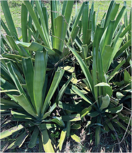
The sisal leaves are extracted from the Agave Sisalana plants shown in . These are abundant in the Vhembe district in Limpopo province, South Africa; in most places, they are considered invasive and often removed.
Figure 1. Actual agave sisalana plant in South Africa Limpopo Vhembe district.
Fiber extraction and treatment
The fibers were mechanically extracted using indigenous methods; after extraction, they are allowed to dry in the open air before further treatment, refer to . The fibers are then immersed in the prepared different solutions for five hours in the acid solution centrifugal plastic tubes. While some of the fibers are treated in deionized water, the rest are treated in 1, 5, 10, 15, 20, and 25% NaOH solution at room temperature for five hours, as shown in , for the measured pH values refer to per solution. After treatment, they were washed in anodized water for another five hours and then dried at 50 ̊C overnight.
Figure 2. (a) Before treatment (b) during alkali treatment.
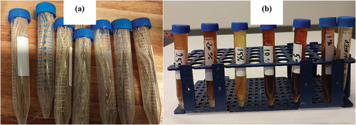
Table 1. Mediums used and pH values.
Mechanical testing
The 44 N load cell from the Cellscale was used for Uniaxial tensile testing on Sisal fibers. A 20 mm sample length of Sisal specimens was experimentally tested at the strain rate of 10−1.s−1 under room temperature (±25 ◦C). The specimens were tested following the D 3379–75 (Reapproved 1989) standard testing method (Materials Citation2000). For consistency and to prevent stress on the fibers during gripping, the paper frame technique was adopted from the previous studies (Adusumalli et al. Citation2019; Kiszewski, Bevilaqua, and De Citation2018; Mathebela et al. Citation2024) for fixing the fibers. The lags on the fiber were manually removed by hand, and only fibers breaking in the middle were considered for evaluation.
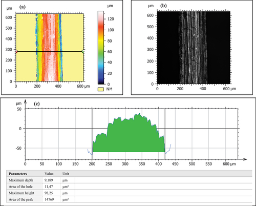
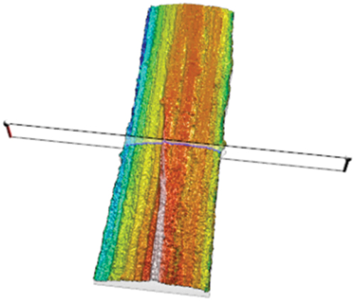
It is then loaded and stressed at a constant strain rate until failure. In this study, the cross-sectional area is measured using the laser confocal microscope, refer to for the analysis process followed to measure the average fiber diameter.
Figure 3. (a) The position of the cross-sectional measurement (b) the actual fibre and (c) results of the cross-sectional area analysis of the untreated fibre.
Fiber characterization
In this study, the fiber morphology is studied using the Zeiss LSM 900, and the surface data is processed in Mountains ConfoMap 9.0 following ISO 25,178. The L filter or λc is taken at 0,0025 mm, and the S filter or λs at 0,8 µm. The fibers’ surface roughness, texture directionality, surface void volume, and PSD (Power Spectral Density) of the surface are studied from the data. For further analysis, the samples were inspected in the SEM (Scanning Electron Microscope), and EDS (Electron Dispersive X-ray Spectroscopy) was run to inspect the chemical changes.
The fiber’s internal microstructure is studied using the Zeiss Xradia510 X-ray microscope (XRM). The instrument makes X-ray sections of the sample, which are then formed together into a 3D tomography image of the sample using separate software. This technology’s classical or conventional version was first developed in the first half of the 20th century, based on single-plane focus X-ray imaging (Villarraga-Gómez et al. Citation2022; Villarraga-Gómez, Herazo, and Smith Citation2019). The scanning parameters used in the study are shown in .
Table 2. Summary of XRM scanning parameters used.
Results and discussion
Internal tomography
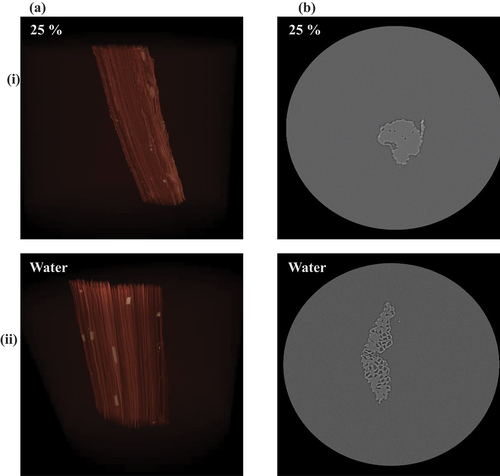
Shown in are the results from the X-ray microscope (XRM) scans. The untreated fiber, as shown in row (i) shows that the fibers’ internal structure is porous or has long channels along its length. However, the treatment causes some collapse of these porous or cavities, as shown in rows (ii) and (iii). Moreover, the degree of collapse is greatly affected by the alkali concentration, as shown in row (iii) at 5%, there’s a complete cavity collapse. With the rest, there’s no complete collapse, as shown in row (ii) and where an almost complete collapse is seen in row (ii) at 15% concentration.
Figure 4. Internal microstructure XRM scans of selected single fibres, column wise (a) is the 3D external scan and (b) the internal cross-sectional scan. Row wise respectively (i) to (iii) is the untreated, 1% and 5% alkali treated fibre.
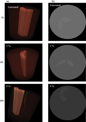
Figure 5. Internal microstructure XRM scans of selected single fibres, column wise (a) is the 3D external scan and (b) the internal cross-sectional scan. Row wise respectively (i) to (iii) is the 10%, 15% and 20% alkali treated fibre.
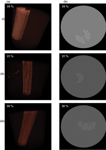
Figure 6. Internal microstructure XRM scans of selected single fibres, column wise (a) is the 3D external scan and (b) the internal cross-sectional scan. Row wise respectively (i) to (ii) is the 25% alkali and water treated fibre.
Measurement of surface properties
Fiber alkali treatment has a profound effect on the fibers’ surface morphology. Moreover, the fibers’ matrix adhesion properties (Arsyad et al. Citation2015; Putra et al. Citation2020). This section discusses the resulting surface or morphology from the treatment. The discussion will be around the conventional properties, texture directionality, surface void volume, and PSD. Refer to for the average measured surface properties per treatment.
Table 3. Results of analyzed surface parameters.
Conventional surface properties
is a summary of the measured conventional surface properties Sq and Sa, respectively, which are the root mean square height and the fibers’ arithmetic mean height area roughness.
Figure 7. Summary of analysis of surface parameters.
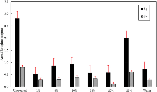
The results show that there was a significant change in the fibers’ surface roughness after treatment. As previously noted, this is due to the removal of other materials that might have still been attached to the fibers. At 25%, there’s a higher roughness after treatment, or no significant surface change can be noted compared to the other treatments, where the change seems almost similar and drastic.
Texture directionality
As shown in , the treatment has no significant effect on the direction of the texture of the fibers. It has a preferred orientation of ≥90 ̊ to the flat end of the fibers, meaning the dominant surface peaks are parallel to the fibers’ length; this is clearly illustrated in .
Figure 8. Surface directionality of samples treated respectively at 1, 5 and 10% (b)-(d), respectively, as compared to the untreated samples at (a).
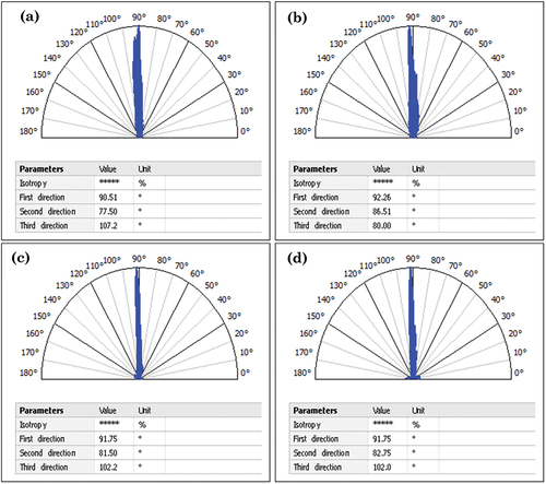
Figure 9. 3-D view of a single fibre’s surface.
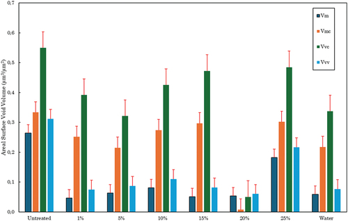
Surface void and material volume parameters
In this analysis, the material volume (Vm), core material volume (Vmc), core void volume (Vvc), and dale void volume (Vvv) are discussed; refer to for a summary of the results. The surface volume parameters in untreated fibers are higher than those of the treated fibers. This is also owed to the high roughness previously reported. The lowest reported results were at 20% with an extremely low Vmc. This also shows that a significant amount of material is removed from the fibers’ surface during treatment.
Figure 10. Summary of surface material void volume results.
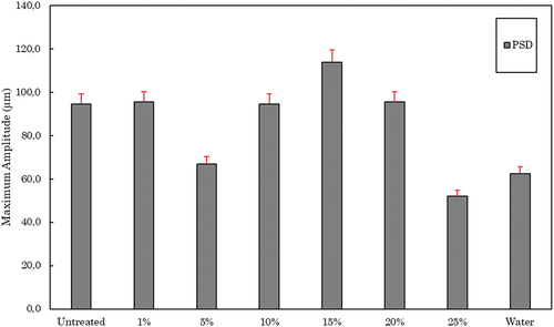
Power Spectral Density (PSD) analysis
The results of the PSD analysis are summarized in , comparing the maximum amplitude per treatment. A higher maximum amplitude is detected at 15%, while the second highest is at untreated, 1%, 10%, and 20%, with the lowest at 25%. This is contrary to the conventional functional properties analyzed in previously analyzed. This may be due to PSD’s analysis capability to characterize different spatial frequency regions on the complete surface roughness, which is usually not fully described by usual roughness analysis methods (Li et al. Citation2020; Vepsäläinen et al. Citation2012).
Figure 11. Summary of PSD analysis.
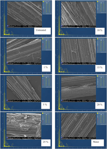
The EDS chemical analysis and SEM micrographs of the fiber surfaces are illustrated in . The micrographs of surface morphology show a clear change due to treatment alkali concentration, where at 25%, the surface degradation and change are very pronounced. Moreover, the EDS analysis shows increased Na with the concentration treatment solution. The results reinforce the surface roughness findings, which showed a higher roughness at 25% compared to the treatment from the rest of the solutions.
Figure 12. Variations of surface morphologies caused by the treatment.
Mechanical test results
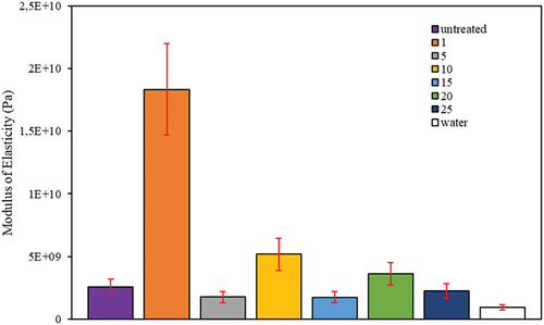
Young’s modulus of elasticity is greatly affected by the alkali percentage, as illustrated in . The lowest modulus is reported at the lowest pH solution, which was just deionized water, while the highest is at 1% concentration. This illustrates that although alkali treatment may improve the fiber’s mechanical properties, it will inversely affect the properties. This is also because the treatment depredates the fiber structure, as illustrated in the XRM scans in , also evident in the changes in the surface topography reported; this concurs with observations in (Bekele, Lemu, and Jiru Citation2022).
Figure 13. Results of the maximum calculated young’s modulus of elasticity per treatment.
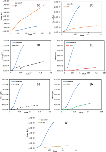
The stress – strain curves are shown in ; each concentration is compared to the untreated. This also supports the previous discussion; in this case, the stress – strain behavior also shows that there was a degradation or size reduction of the fiber during treatment.
Figure 14. Stress - strain results of treated fibres compared with the untreated or as received fibres.
Fracture analysis of selected fibers
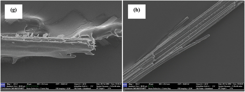
are SEM micrographs of the fracture ends per treatment. The untreated fiber shows some slight degree of necking or deformation at failure. However, with fibers treated with 1%, 5%, 15%, 20%, and water, the failure modes seem similar, where the fibers rapture along their lengths before complete failure. While fibers treated with 10% alkali seem brittle, as shown by the clean break in the micrograph , this is almost similar again with 20% alkali-treated fibers in . The mechanical test results show considerable agreement with results researchers reported previously (Mydin Citation2022; Ndoumou et al. Citation2022; Veerasimman et al. Citation2022). The slight disappearances may be due to the plants’ cultivation environment, such as soil types and nutrition.
Figure 15. SEM micrographs of fractured ends of selected fibers: (a) untreated, (b) 1%, (c) water treated, (d) 5%, (e) 10% and (f) 15%.
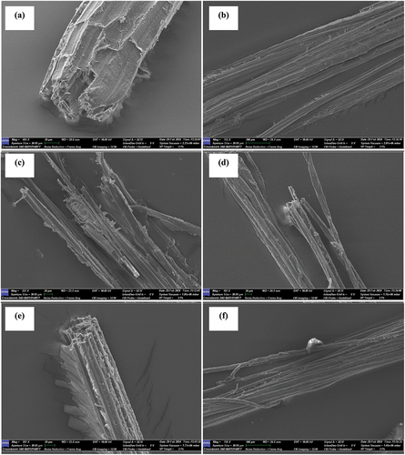
Figure 16. SEM micrographs of fractured ends of selected fibers: (g) 20 % and (h) 25 %.
Conclusion
In this study, sisal plant fibers were mechanically extracted and subjected to solutions of different alkali concentrations (1, 5, 10, 15, 20, and 25%) NaOH. The fibers were characterized internally using the XRM and externally with LSM to study the surface topology, and finally, they were mechanically tested. The untreated fibers have a hollow internal structure before treatment, as illustrated in the XRM scans. After treatment, the hollow structure seems to collapse depending on the solution concentration. The treatment reduces the fiber’s surface properties, particularly the roughness, while the surface’s asperity isotropy or directionality remains unchanged. The mechanical tests showed that the treatment can improve fibers’ strength; however, this also depends on the concentration. Where the highest modulus was reported at 1% concentration, thereafter, the fibers’ strength seemed to decrease, showing degradation of the fibers. SEM micrographs of the fractured ends show that the failure modes are unique to the alkali treatment concentration. Showing that there was an increase in hardness and degradation of the fibers based on their brittle failure.
The findings show that alkali treatment at a concentration higher than 1% does not improve the fiber’s mechanical properties. Moreover, there is a decrease in fiber’s size and a reduction in its internal structure. Furthermore, fiber’s surface roughness properties are affected by treatment. This will have a pronounced effect on the fiber and matrix interfacial properties.
Highlight
The article reports on the effects of alkali concentrations treatment on sisal natural fibers and the following are the highlights of the article:
The changes in areal surface roughness properties caused by treatment.
The internal microstructure of single fibers, using X-ray microscopy.
The resulting failure modes caused by the treatment.
Acknowledgments
The author(s) are grateful for the support offered by the University of South Africa and laboratory staff of the Mechanical Engineering Department.
Disclosure statement
No potential conflict of interest was reported by the author(s).
References
- Adusumalli, R. B., K. C. Venkateshan, C. Kunchi, and N. Rahbar. 2019. “Tensile Testing of Single Fibres.” Procedia Structural Integrity [Internet]. 14:150–17. https://doi.org/10.1016/j.prostr.2019.05.020.
- Amsalu Fode, T., Y. A. Chande Jande, T. Kivevele, and N. Rahbar. 2024. “A Review on Degradation Improvement of Sisal Fiber by Alkali and Pozzolana for Cement Composite Materials.” Journal of Natural Fibers [Internet]. 21. (1). Accessed April 15, 2024. https://www.tandfonline.com/action/journalInformation?journalCode=wjnf20.
- Arsyad, M., I. N. G. Wardana, Pratikto, and Y. S. Irawan. 2015. “The Morphology of Coconut Fiber Surface Under Chemical Treatment. Matéria (Rio de Janeiro) [Internet]. Matéria (Rio de Janeiro) 20 (1): 169–177. Accessed December 28, 2023. https://www.scielo.br/j/rmat/a/YYnkfFw6mDFkHS5XTPZkNCk/?lang=en.
- Asaduzzaman, S. M., and G. M. S. Islam. 2023. “Using Jute Fiber to Improve Fresh and Hardened Properties of Concrete.” Journal of Natural Fibers [Internet]. 20 (2). Accessed April 15, 2024. https://doi.org/10.1080/15440478.2023.2204452.
- Bao, H., H. Meng, W. You, and F. Qin. 2019. “Study on the Corrosion Resistance of Sisal Fiber Concrete in Marine Environment.” SN Applied Sciences [Internet]. 1 (12): 1–6. Accessed April 15, 2024. https://link.springer.com/article/10.1007/s42452-019-1551-8.
- Bekele, A. E., H. G. Lemu, and M. G. Jiru. 2022. “Experimental Study of Physical, Chemical and Mechanical Properties of Enset and Sisal Fibers.” Polymer Testing 106:107453. https://doi.org/10.1016/j.polymertesting.2021.107453.
- Bharathi, S. V., S. Vinodhkumar, and M. M. Saravanan. 2021. “Strength Characteristics of Banana and Sisal Fiber Reinforced Composites.” IOP Conf Ser Mater Sci Eng [Internet] 1055 (1): 012024. Accessed December 21, 2023. https://iopscience.iop.org/article/10.1088/1757-899X/1055/1/012024.
- Faheed, N. K. 2024. “Advantages of Natural Fiber Composites for Biomedical Applications: A Review of Recent Advances.” Emergent Materials [Internet]. 7 (1): 63–75. Accessed April 23, 2024. https://doi.org/10.1007/s42247-023-00620-x.
- Hasanuddin, I., I. Mawardi, N. Nurdin, and R. P. Jaya. 2023. “Evaluation of Properties of Hybrid Laminated Composites with Different Fiber Layers Based on Coir/Al2O3 Reinforced Composites for Structural Application.” Results in Engineering 17:100948. https://doi.org/10.1016/j.rineng.2023.100948.
- Kiszewski, A. E., M. Bevilaqua, and A. L. De. 2018. “Alopecia Areata: A New Therapeutic.” International Journal of Trichology 9 (1): 50–53. https://doi.org/10.4103/ijt.ijt_14_18.
- Lakshmi Narayana, V., and L. Bhaskara Rao. 2021. “A Brief Review on the Effect of Alkali Treatment on Mechanical Properties of Various Natural Fiber Reinforced Polymer Composites.” Materials Today: Proceedings 44:1988–1994. https://doi.org/10.1016/j.matpr.2020.12.117.
- Li, Q., Y. Deng, J. Li, and W. Shi. 2020. “Roughness Characterization and Formation Mechanism of Abrasive Air Jet Micromachining Surface Studied by Power Spectral Density.” Journal of Manufacturing Processes 57:737–747. https://doi.org/10.1016/j.jmapro.2020.07.039.
- Lobregas, M. O. S., E. V. D. Buniao, and J. L. Leaño. 2023. “Alkali-Enzymatic Treatment of Bambusa Blumeana Textile Fibers for Natural Fiber-Based Textile Material Production.” Industrial Crops and Products 194:116268. https://doi.org/10.1016/j.indcrop.2023.116268.
- Makinde-Isola, B. A., A. S. Taiwo, I. O. Oladele, A. D. Akinwekomi, S. O. Adelani, and L. N. Onuh. 2024. “Development of Sustainable and Biodegradable Materials: A Review on Banana and Sisal Fibre Based Polymer Composites.” Journal of Thermoplastic Composite Materials [Internet]. 37 (4): 1519–1539. Accessed April 23, 2024. https://journals.sagepub.com/doi/full/10.1177/08927057231186324?casa_token=hfJjjPjjlbEAAAAA%253ALdpLyxHHJEhMWFpMm0Nk345oRtI6JLeFkBxoJh7EgW1Q5uKBAsYF9_C9sFArbkusm1e7WNvNakAA_f0.
- Materials, S. 2000. “Standard Test Method for Tensile Strength and Young’s Modulus for High-Modulus Single-Filament Materials.” System 75:1–5.
- Mathebela, L., R. Sigwadi, T. Lekwana, H. Ngwangwa, T. Pandelani, and F. Nemavhola. 2024. “Dataset from the Uniaxial Tensile Testing of Human Curly Hair Fibers Under Different Conditions.” Data in Brief [Internet]. 52:109943. https://doi.org/10.1016/j.dib.2023.109943.
- Mydin, M. A. O. 2022. “Investigating the Effect of Sisal Fibre Content on Durability Properties of Lightweight Foamed Concrete.” Advances in Science and Technology Research Journal [Internet] 16 (2): 141–149. Accessed April 232024, https://doi.org/10.12913/22998624/147065.
- Ndoumou, R. L., and D. Soulat, A. R. Labanieh, M. Ferreira, L. Meva’a, J. Atangana Ateba. 2022. “Characterization of Tensile Properties of Cola Lepidota Fibers.” Fibers 10:6 [Internet]. 2022 [cited2024 Apr 23];10:6. Available from: https://www.mdpi.com/2079-6439/10/1/6/htm.
- Noorunnisa Khanam, P., and H. P. S. Abdul Khalil, G. Ramachandra Reddy, S. Venkata Naidu. 2011. “Tensile, Flexural and Chemical Resistance Properties of Sisal Fibre Reinforced Polymer Composites: Effect of Fibre Surface Treatment.” Journal of Polymers and the Environment [Internet]. 19 (1): 115–119. Accessed November 1, 2023. https://link.springer.com/article/10.1007/s10924-010-0219-7.
- Putra, I. S., B. A. Budiman, P. L. Sambegoro, S. P. Santosa, A. I. Mahyuddin, K. Kishimoto, K. Inaba, et al. 2020. “The Influence of Fiber Surface Profile and Roughness to Fiber–Matrix Interfacial Properties.” Journal of Composite Materials [Internet]. 54 (11): 1441–1452. Accessed December 28, 2023. https://doi.org/10.1177/0021998319883418.
- Rao, K. M. M., and K. M. Rao. 2007. “Extraction and Tensile Properties of Natural Fibers: Vakka, Date and Bamboo.” Composite Structures 77 (3): 288–295. https://doi.org/10.1016/j.compstruct.2005.07.023.
- Rocky, B. P., and A. J. Thompson. 2020. “Production and Modification of Natural Bamboo Fibers from Four Bamboo Species, and Their Prospects in Textile Manufacturing.” Fibers and Polymers [Internet]. 21 (12): 2740–2752. Accessed December 21, 2023. https://doi.org/10.1007/s12221-020-1208-7.
- Salih, A. A., R. Zulkifli, and C. H. Azhari. 2020. “Tensile Properties and Microstructure of Single-Cellulosic Bamboo Fiber Strips After Alkali Treatment.” Fibers 8:26 [Internet]. 2020 [Accessed December 21,];8:26. https://www.mdpi.com/2079-6439/8/5/26/htm.
- Shu, B., Q. Ren, L. Hong, Z. Xiao, X. Lu, W. Wang, J. Yu, N. Fu, Y. Gu, and J. Zheng. 2021. “Effect of Steam Explosion Technology Main Parameters on Moso Bamboo and Poplar Fiber.” Journal of Renewable Materials 9 (3): 585–597.
- Thomas, B. C., and Y. S. Jose. 2022. “A Study on Characteristics of Sisal Fiber and Its Performance in Fiber Reinforced Concrete.” Materials Today: Proceedings 51:1238–1242. https://doi.org/10.1016/j.matpr.2021.07.312.
- Veerasimman, A., V. Shanmugam, S. Rajendran, D. J. Johnson, A. Subbiah, J. Koilpichai, U. Marimuthu, et al. 2022. “Thermal Properties of Natural Fiber Sisal Based Hybrid Composites – a Brief Review.” Journal of Natural Fibers [Internet]. 19 (12): 4696–4706. Accessed April 23, 2024. https://doi.org/10.1080/15440478.2020.1870619.
- Vepsäläinen, L., P. Pääkkönen, M. Suvanto, and Tapani A. Pakkanen. 2012. “Frequency Analysis of Micropillar Structured Surfaces: A Characterization and Design Tool for Surface Texturing.” Applied Surface Science 263:523–531. https://doi.org/10.1016/j.apsusc.2012.09.098.
- Villarraga-Gómez, H., E. L. Herazo, and S. T. Smith. 2019. “X-Ray Computed Tomography: From Medical Imaging to Dimensional Metrology.” Precision Engineering 60:544–569. https://doi.org/10.1016/j.precisioneng.2019.06.007.
- Villarraga-Gómez, H., N. Kotwal, R. Parwani, D. Weiß, M. Krenkel, W. Kimmig, C. Graf Vom Hagen, et al. 2022. “Improving the Dimensional Accuracy of 3D X-Ray Microscopy Data.” Measurement Science and Technology [Internet]. 33 (7): 074002. Accessed December 27, 2023. https://doi.org/10.1088/1361-6501/ac5a30.