
Abstract
Mineral wool fibers can be released into the air during the production and handling of a mineral wool product where a small fraction of fibers will stay airborne and can potentially be inhaled. The aerodynamic fiber diameter determines how far an airborne fiber can pass through the human airway. Respirable fibers with an aerodynamic diameter < 3 µm can reach the deep part of the lungs (i.e., the alveolar region). Binder material (i.e., organic binder and mineral oil) is used in the production of mineral wool products. However, at the current stage, it is unknown if airborne fibers can contain binder material. We explored binder presence on airborne respirable fiber fractions being released and collected during the installation of two mineral wool products (a stone wool product and a glass wool product). Fiber collection was done by pumping a controlled air volume (2, 13, 22, and 32 l/min) through polycarbonate membrane filters during the installation of the mineral wool products. The morphological and chemical composition of the fibers were studied using scanning electron microscopy coupled with energy-dispersive X-ray spectroscopy (SEM-EDXS) analysis. The study demonstrates that binder material is found on the surface of the respirable mineral wool fiber mainly as circular or elongated droplets. Our findings suggest that respirable fibers explored in previous epidemiological studies, which have been used for proving a lack of hazardous effects of mineral wool on humans, may have also contained binder materials on the fibers.
Introduction
Mineral wool insulation products are used globally in the construction industry for thermal and acoustic insulation of the building envelope, as facade cladding and fire protection. In addition, mineral wool products are used for a variety of other applications such as growing substrates in the horticultural industry, noise-reducing acoustic fences, and urban water management solutions. The mineral wool insulation market consists of three main groups of material, i.e., stone, glass, and slag wool (Yue and Solvang Citation2021). The division into groups is made based on the raw material used and hence the chemical composition of the fiber. Typically, stone, glass, and slag wool are produced using two different spinning technologies (Zu et al. Citation2021) that both result in a product consisting of inorganic fibers generally having a geometric mean diameter (GMD) equal to 2–6 µm. For stone and slag wool, the product also includes inorganic non-fiberized and quenched melt particles with a spherical shape.
In addition, a certain amount of organic binder material (generally not more than up to a maximum of 10 wt. % of the total wool mass) is applied as an aqueous solution of binder, aminosilane, and mineral oil, to the mineral wool fibers to join the individual fibers. This solution is often and, in this work, referred to as a binder material or an organic material. The major component of the binder material has traditionally been a phenol-urea-formaldehyde (PUF) thermosetting resin (Kowatsch Citation2010). However, new binder types have recently been introduced and developed (Potter and Olang Citation2013; Hjelmgaard et al. Citation2018). Simultaneously to the binder application, mineral oil can be applied which is used as a water repellent with an additional aminosilane coupling agent. The latter is used to enhance the adhesion of the binder to the fiber surface. Subsequently, the fibers are collected and formed into a wool web that is cured by a hot air stream blown through the wool web in a curing oven.
When handling mineral wool products at various workplaces (i.e., production, installation, and demolition), fibers can be released. These specific fibers are called airborne fibers. To measure the exposure level in the work environment the number of fibers is counted (fibers per cm3). The World Health Organization (WHO) (WHO Citation1997) has established an airborne fiber sampling method that forms the basis for the European standard EN 689 for workplace atmosphere assessment of exposure by inhalation (EN 689 Citation1995). This sampling strategy (e.g., sampling times, activities during sampling) is adopted in previous research (Campopiano et al. Citation2012) as well as in this work. Jacob et al. (Citation1993) and Marchant et al. (Citation2002) report concentrations of airborne mineral wool fibers (stone, glass, and slag) in a range of 0.5 − 1 fiber/cm3, based on a large database of airborne fiber concentrations measured during manufacturing and installation in the period from 1984–2000. It should be noted that the concentration of mineral wool fibers measured in outdoor and indoor air in non-occupational settings are generally much lower than in occupational settings related to mineral wool fiber production or installation. Table 36 in the International Agency for Research on Cancer (IARC) Monograph vol 43 (IARC Citation1988) reports that the concentration of fibers is < 0.001 fiber/cm3 for outdoor and inside buildings and < 1.0 fiber/cm3 for production or installation. A recent study by Marchant et al. (Citation2021) updates the findings on occupational exposure to glass wool fibers and no major changes in the workers’ exposure in the glass wool manufacturing industries are found and the manufacturing exposure level is well below 1 fiber/cm3.
Whether a fiber is inhaled depends on the aerodynamic diameter of the fibers, the velocity of the surrounding air, and the individual breathing rate (WHO Citation1999). Airborne particles and fibers can be inhaled and deposited in three different regions of the respiratory tract: (1) the extrathoracic (the upper part of the airways); (2) the tracheobronchial (the middle part of the airways); and (3) the alveolar regions (the deepest part of the airways) (Brown Citation2015). The probability of fibers depositing in the alveolar region also depends on the aerodynamic diameter of the fiber, airway dimensions, breathing pattern, and fiber density (IARC Citation2002). Fibers behave differently compared to other particles. Fibers of up to 100 µm in length have been found in the respiratory system, indicating that the fiber diameter and not the length primarily governs the ability to pass into the lungs (WHO Citation1999). Thus, an airborne fiber is defined as a particle having a diameter (d) less than 3 µm and length (l) greater than 5 µm, with a length-to-width ratio greater than 3:1 (WHO Citation1997). These specific fibers are also by WHO (IARC Citation2002) defined as respirable and they can reach the deepest part of the lung, i.e., the alveolar region. This definition of an airborne respirable fiber is being used in the present study (d < 3 µm, l > 5 µm, and l:d > 3:1). It should be noted that the criteria for respirable fibers and particles may differ depending on the selected standard, such as EN 481 or ISO 7708. In addition, it is stated by the Scientific Committee on Occupational Exposure Limit Values (SCOEL) that respirable fibers should be shorter than 100–200 µm (SCOEL Citation2011).
According to the 3D paradigm of fiber toxicity (dose, dimension, and durability) (Maxim et al. Citation2006; Bernstein Citation2007), airborne fibers can be of concern under certain circumstances. The respirable ones can reach the alveolar region of the lung (Bellmann Citation2010) and could pose a hazard if these fibers are biopersistent. A biopersistent fiber that remains in the lung without being cleared can potentially lead to both inflammatory and fibrotic processes (SCOEL Citation2011) and in some cases eventually to cancer. A hazard assessment is typically based on various data points (e.g., in silico, in vitro, in vivo, and epidemiological data). Normally representing a real-life scenario, epidemiological data is typically considered the most relevant data. Mineral wool products are reviewed for potentially hazardous effects on human health by IARC under the WHO (IARC Citation1988, Citation2002; Baan and Grosse Citation2004).
The IARC evaluation (IARC Citation2002) is partly based on major epidemiological studies on workers in mineral wool production, as the workers could have been exposed to airborne respirable fibers released during the production of mineral wool products. IARC concludes that the evidence for carcinogenicity in humans is inadequate, and there is limited evidence in experimental animals for the carcinogenicity of both stone and glass wool (IARC Citation2002), hence, mineral wool fibers fall under Category Group 3—the agent is not classifiable as to its carcinogenicity to humans.
Deposited fibers are cleared from the lungs via both physiological clearance processes (mechanical translocation/removal) and physico-chemical processes (chemical dissolution and leaching, mechanical breaking) (Oberdörster Citation2000). Fiber removal therefore covers several mechanisms including dissolution and breakage as well as phagocytosis by alveolar macrophages for fibers < 20 µm in length (Maxim et al. Citation2006).
From a regulatory perspective, non-biopersistent mineral wool fibers are registered as MMVF (man-made vitreous fibers) under REACH under the EC number 926-099-9. Further, a regulatory framework is applied to mineral wool fibers in Europe. Note Q of the European Regulation (EC) No 1272/2008 (CLP) (EC Citation2008) defines a fiber as non-biopersistent if one of the following conditions is fulfilled: (1) short-term biopersistence inhalation test demonstrates that the weighted half-life is < 10 days for fibers longer than 20 µm; (2) short-term biopersistence intratracheal installation test demonstrates that the weighted half-life is < 40 days for fibers longer than 20 µm; (3) intraperitoneal test shows no evidence of carcinogenicity excess; or (4) long-term inhalation test shows absence of relevant pathogenicity or neoplastic changes. It should be noted that Note Q only considers testing of fibers produced without binder.
It is accepted that the biopersistence of mineral wool fibers depends partly on their chemical composition (Knudsen et al. Citation1996; Eastes et al. Citation2000; Guldberg et al. Citation2000) as physico-chemical processes is one of the factors involved in the biopersistence of fibers. A good indication of the fiber’s biopersistence is the dissolution rate of the specific fiber (Guldberg et al. Citation2002) derived in acellular in vitro dynamic tests as described by Sebastian et al. (Citation2002). Several studies demonstrate a correlation between in vivo and in vitro results: biopersistence in vivo is low when the in vitro dissolution rate is high (Eastes et al. Citation2000; Guldberg et al. Citation2000, Citation2002). Barly et al. (Citation2019) collected stone wool fibers from a production line and demonstrated that the dissolution rate of stone wool fibers with applied organic material (up to 6 wt. % of total wool mass – binder and mineral oil) is the same as for stone wool fibers without applied organic material. It is noted that the chemical composition of the fiber material is the same independent of whether organic material was applied to the fiber material or not. A recent study by Okhrimenko et al. (Citation2022) confirms this finding, whereas studies by Wohlleben et al. (Citation2017) and Sauer et al. (Citation2021) indicated that binder removal by heating may increase the in vitro dissolution rate of stone wool fibers. However, binder effects on dissolution rates were not confirmed by other authors (Barly et al. Citation2019; Okhrimenko et al. Citation2022) neither by the same group of authors (Wohlleben et al. Citation2017; Sauer et al. Citation2021) in their latest study (Hirth et al. Citation2021), where they demonstrated no correlation between binder mass or modeled organic layer thickness and the in vitro dissolution rate of commercially available stone wool products. Also, Potter and Olang (Citation2013) demonstrate that there is no measurable difference between the dissolution rates of glass wool fibers with binder and glass wool fibers without binder. Earlier, Bauer (Citation1998) concludes that binder present on the fiber surface does not represent a significant barrier to fiber degradation in the lung, and recent studies show that binder does not completely cover the fiber surface (Okhrimenko et al. Citation2022, Citation2023). Hence, if binder is observed on the fibers, it does not influence the biopersistence of the fiber. It is not known whether or not binder was present on respirable fibers inhaled by humans during epidemiological studies. To inform the discussion of the binder’s possible effects on biosolubility and the biopersistence of mineral wool fibers, it is important to study the presence of binder on respirable fibers.
This study aims to explore whether binder material can be identified on respirable mineral wool fibers by characterizing the respirable fiber morphology and specifically to what extent the respirable fibers are covered by an organic binder material. Such fibers would likely be the ones being assessed in epidemiological studies on mineral wool workers. Further, the fiber morphology of a stone and a glass wool product is presented. The airborne fiber collection was done during mineral wool installation that mimics a typical work scenario. During the product installation, stationary air samples were collected according to EN 698 (1995), the size of the selected filter was chosen to follow WHO (Citation1997), and sampling positions were settled according to ISO 16000-7 (Citation2007). Fiber morphology and the occurrence of binder material on fiber surfaces were explored using scanning electron microscopy (SEM), and the chemical composition of the fiber and binder areas were characterized using energy dispersive X-ray spectroscopy analysis (EDXS).
Experimental procedure
Stone wool product sample (SW-A)
The commercially available product ROCKWOOL A-batts (965 x 560 x 95 mm), manufactured by ROCKWOOL Danmark A/S was used in this study, hereafter named sample SW-A. The product density was 30 kg/m3 and the binder was a phenol-urea-formaldehyde (PUF) thermosetting resin. Mineral oil and 3-aminopropylsilane were added to the PUF binder during production.
Glass wool product sample (GW-A)
The commercially available product ISOVER 37 Basic Formstykker (960 x 600 x 95 mm), manufactured by Saint Gobain Denmark A/S was used in this study, hereafter named sample GW-A. The product density was 18 kg/m3 and the binding material is unknown to the authors.
Organic content determination
The organic content of the solid matter was determined by measuring the weight loss of the 30 g product sample after heat treatment at 590 °C for 20 min and 450 °C for 120 min, for SW-A and GW-A, respectively. The temperatures follow specifications by Christensen et al. (Citation1993) and the temperatures are approximately 100 °C below their standard glass transition temperatures (Yue and Solvang Citation2021).
Scanning electron microscopy (SEM) of original product sample
The morphology of the original product samples SW-A and GW-A were investigated using SEM image analysis. Imaging of the product was performed on a small tuff of as-produced fiber material in an SEM (Tescan Vega 3) and on a small tuff of fiber material heat treatment for 20 min at 590 °C for sample SW-A and 120 min at 450 °C for sample GW-A, to remove organic matter.
Fiber diameter distribution
The fiber diameter distributions of samples SW-A and GW-A (the original product samples) were determined using SEM (Tescan Vega 3) image analysis. The specific fiber samples prepared for fiber diameter distribution measurement were initially heated for 20 min at 590 °C for sample SW-A and for 120 min at 450 °C for sample GW-A to remove organic matter. Thereafter, samples were sieved to remove the fraction > 63 µm to ensure that shots and un-fiberized material were not included in the fiber sample for diameter measurement, which is specifically important for the stone wool sample. Fiber material was distributed evenly on an SEM stub to assure no overlap of fibers and coated with gold. SEM was operated at 30 kV. The length-weighted diameter distribution was determined by measuring the diameter of fibers crossing a slice of an image. Fibers were identified as features with two parallel sides. For reasonable statistics, the number of fibers measured should be at least 100; however if the distribution is broad, a greater number of fibers should be measured (Christensen et al. Citation1993; Koenig et al. Citation1993). A total of 1,724 fibers were analyzed for sample SW-A, and 1,191 were analyzed for sample GW-A.
Installation of mineral wool products
Installation of the mineral wool products was done by a carpenter in a specially designed test room consisting of a narrow U-shaped corridor (1.2 m width, 2.5 m height, and 8.4 m long) with a ceiling. The walls of the room were made of a steel frame construction covered with gypsum boards on the outside. One end of the corridor was sealed off with plastic foil during installation, while the other end was open and served as an entrance to the working area. The insulation product was installed in the steel frame on the inner side of the corridor. The dimensions of the frame required the carpenter to cut the insulation slabs to make them fit firmly in the frames. The installation represented a typical work situation.
Two installation sequences were carried out for the installation of stone wool. In between, the installed material was removed, and the test room was thoroughly ventilated by forced cross-airing with fans. During ventilation, the plastic foil covering one end of the corridor was removed and then placed back before the second installation with new material. One installation sequence was carried out for the installation of glass wool. Each installation of the insulation product took approximately 2 hr. Removing the insulation took approximately 30 min. Stone and glass wool fibers were visible in the air inside the corridor during the installation.
Airborne fiber sampling
The airborne fiber sampling was carried out by a work environment measurement expert from the test institute Danish Technological Institute. Stone wool product installation was done first, followed by glass wool product installation, with sampling conducted as follows:
For the first installation sequence, six samples were taken after the installation procedure. During the second installation sequence, another six samples were taken, and for three of the samples it was chosen to include the product removal process in the sampling period.
Only one installation sequence was prepared and one sample was taken after the installation procedure, whereas for the other eight samples, it was chosen to include the product removal process in the sampling period, to ensure that as much fiber material as possible was collected.
The sampling of airborne mineral wool fibers was carried out by pumping a controlled air volume through polycarbonate membrane filters. The sampling strategy was in accordance with EN 689 (Citation1995). All filters used in the study had a pore size of 0.8 μm and diameters as prescribed by WHO (Citation1997). The sampling points were placed in the middle of the corridor at a height of approximately 1.2 m above the floor following the standard ISO 16000-7 (Citation2007). In the study, relatively high air flow rates were also used to assure sufficient fiber material to study, however, the number of collected respirable fibers is most probably higher than in a typical work situation. Three different sampling methods were used based upon (1) EN 481, (2) WHO (Citation1997) and ISO16000-7, or (3) WHO (Citation1997) and MDHS 39/4 (Citation1995). These three sampling methods are traditionally used to sample (1) respirable particles, (2) measure total concentration of airborne fibers, and (3) measure total fiber concentration. It was initially decided to use all three methods during product installation to assure that at least one of the methods would collect enough material for further characterization of the airborne fibers and specifically the respirable ones. Methods 1, 2, and 3 were used for the installation of stone wool whereas Methods 2 and 3 were used for the installation of glass wool. Method 1 was only used for stone wool installation as it was discovered after the stone wool installation that no fibers were collected using Method 1. Quantification of the number of fibers collected on the filters was not the scope of this study, thus the mass of collected material was not determined neither was the number of collected fibers. The methods utilized are as follows:
Method 1
The fibers were sampled on a 37 mm mixed cellulose ester filter in a cassette (SKT Ltd.) mounted with an aluminum cyclone (SKC 225-01-02 37) using an airflow rate of 1.9 l/min. Gillian GilAir Plus pumps were used. This method is typically used for sampling the respirable fraction of airborne particles, cf. EN 481 (EN 481 Citation1993). The cyclone was mounted to sample only the respirable fibers.
Method 2
The fibers were sampled on a 25 mm polycarbonate filter in a cassette (SKT Ltd.) mounted with an electrically conducting cowl at an airflow rate of 2 l/min. Gillian GilAir Plus pumps were used. As stated in (WHO Citation1997), this method should be used when comparisons are to be made with fiber concentration limit values defined for 4-hr or 8-hr reference periods. Filter cassettes were exposed at an angle of 45° to the horizontal plane in accordance with ISO 16000-7 (Citation2007). Samples SW-B and GW-B were collected.
Method 3
Fibers were sampled on a 25 mm polycarbonate filter in a cassette (SKC Ltd.) with an electrically conducting cowl at an airflow rate of 13 l/min (sample SW-C). Diaphragm pumps (Reciprotor) mounted with a gas meter were used for this sampling. Following (WHO Citation1997), this method should be used when comparisons are to be made with fiber concentration limit values defined for short-term reference periods or to control the effectiveness at which fibers have been cleaned from a certain enclosure (MDHS 39/4 Citation1995). Some samples were collected at an airflow rate of 22 l/min (GW-C) or 32 l/min (Sample SW-D), which is higher than the maximum prescribed flow (16 l/min). Filter cassettes were exposed at an angle of 45° to the horizontal plane in accordance with ISO 16000-7 (Citation2007). Air temperature and relative humidity in the corridor were during stone wool installation at 21–22 °C and 60–70% RH and during glass wool installation at 18–19 °C and 55% RH.
Characterization of collected samples
lists the samples collected for characterization. SEM images were taken of the original product sample before and after heat treatment (samples SW-A and GW-A). In addition, fibers collected on membrane filters during the installation of the product (samples SW-B, SW-C, SW-D, GW-B, and GW-C) were examined. SEM images of samples SW-A and GW-A (original fibers and heat-treated original fibers) were taken of fibers placed directly on a microscope stub. SEM images of samples SW-B, SW-C, SW-D, GW-B, and GW-C were either taken directly on a membrane filter mounted on a microscope stub or on microscope stubs to which the fibers were moved. The SEM was operating at an acceleration voltage of 5 kV with backscatter electrons (BSE). It is found that a fiber area covered with organic material is not visible under high-voltage operation (Barly et al. Citation2019). For samples SW-B, SW-C, SW-D, GW-B, and GW-C (the airborne fibers collected after installation), the diameter was determined for individual fibers on the SEM image, and fibers fulfilling the defined criteria of MDHS 39/4 (Citation1995) and WHO (Citation1997) for respirable fibers (length > 5 µm, width < 3 µm, and length:width ratio > 3:1) were selected for further characterization. Their surface was inspected for binder presence. Binder visible by SEM analysis was observed as dark areas on stone and glass wool fibers, this goes for both fibers collected directly from the product and fibers collected after installation of the product. These areas were analyzed by scanning with EDXS along the fiber length crossing a dark spot for the fibers collected after installation. Elements typical for binder—carbon and oxygen—and some elements typical for inorganic constituents of the fiber—oxygen, silicon, aluminum, and magnesium for SW and oxygen, silicon, and sodium for GW (Zu et al. Citation2021)—were tracked along the length of the fiber. The dimension (length and width) of the binder covering areas was evaluated on selected stone and glass wool fibers collected using a 2, 13, 22, or 32 l/min air flow rate during sampling.
Table 1. Collected samples and analysis techniques used in this study.
Results
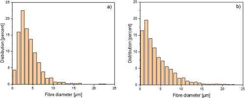
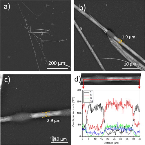
SEM image of the original stone wool product (Sample SW-A) is shown in . The product has an organic content of 2.0 wt. % and the geometric mean diameter (GMD) is 3.3 µm. 43% of the measured fibers have a fiber diameter of less than 3 µm. The fiber diameter distribution is shown in . SEM image of the original glass wool product (sample GW-A) is shown in . The product has an organic content of 6.4 wt. % and the geometric mean diameter (GMD) is 2.8 µm. 50% of the measured fibers have a fiber diameter of less than 3 µm. The fiber diameter distribution is shown in .
Figure 1. Scanning electron microscope (SEM) image (BSE 5 kV) of the stone wool product used in the present study: (a) sample SW-A ROCKWOOL A-Batts density of 30 kg/m3 and organic content 2.0 wt. % of solid matter; (b) sample SW-A—light grey is the fiber (A) and dark areas on the fibers are binder (B); (c) and (d) sample SW-A where the binder material was removed by heat treatment of the sample at 590 °C for 20 min.
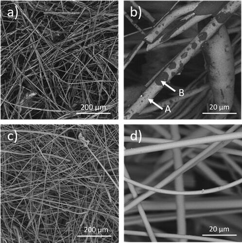
Figure 2. Scanning electron microscope (SEM) image (BSE 5 kV) of the glass wool product used in the present study: (a) sample GW-A – 37 ISOVER Basic Formstykker density of 18 kg/m3 and organic content 6.4 wt. % of solid matter; (b) sample GW-A—light grey is the fiber (A) and dark areas on the fibers are binder (B); (c) and (d) sample GW-A where the binder material was removed by heat treatment of the sample at 450 °C for 120 min.
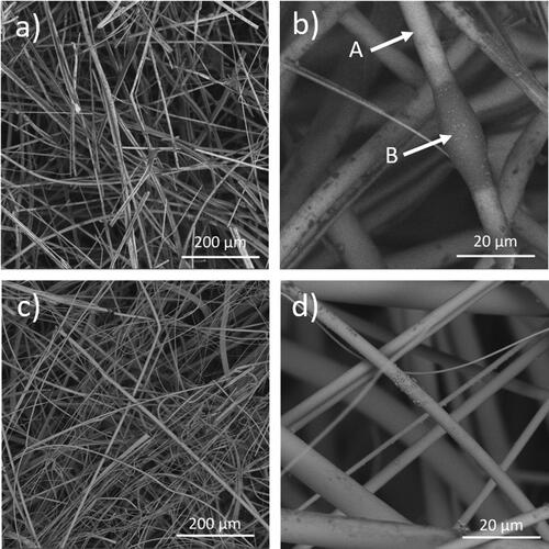
Figure 3. Fiber diameter distribution of (a) sample SW-A (product type is ROCKWOOL A-Batts density of 30 kg/m3) and (b) sample GW-A (product type is 37 ISOVER 37 Basic Formstykker density of 18 kg/m3).
The SEM analysis of filters sampled after collection of airborne and respirable SW and GW fibers, respectively utilizing Methods 1, 2, or 3, show the following:
On the filters collected using Method 1, no stone wool fibers were found when inspecting the filter using SEM. This method uses a cyclone that is designed for collecting respirable airborne particles. It is developed to meet the ACGIH®/CEN/ISO size-selection curve, with a 50% cut-point at 4.0 μm (Jimenez et al. Citation2012). As no fiber material was collected using this method, Method 1 was not repeated for the glass wool product installation session as it is anticipated that also for glass wool fibers no fiber material would be collected, and hence no fiber material for further analysis of the occurrence of organic material on respirable fibers.
and show the SEM image of samples SW-B and GW-B, airborne fibers collected with Method 2 using 2 l/min airflow. Dark areas on stone and glass wool fiber surfaces are observed in BSE mode for fibers < 3 µm in diameter, which are defined as respirable fibers according to (IARC Citation2002). SEM BSE mode is sensitive to the atomic number, showing light elements darker than heavy ones. EDXS scans were performed across the dark areas to investigate the elemental composition of observed dark areas ( and ). A pronounced peak in carbon signal intensity as well as a decrease in oxygen and other elements typical for inorganic constituents of the fibers are observed for both stone and glass wool fibers when entering the dark areas. The carbon signal is attributed to an organic substance, i.e., binder, covering the inorganic mineral wool fiber surfaces. Typically, the carbon signal is found for both the stone and the glass wool fibers in the dark areas, identified as organic binder with EDXS, and seen as droplets along the fibers. These droplets have a circular or elongated shape with a diameter of less than 3 µm and a length of less than 5 µm, as seen on SEM images of the collected respirable fibers ( and ). The size range of the binder droplets is available for encapsulation by macrophages (and therefore lung clearance) in case binder droplets would be detached from the fiber surface as a result of the dissolution process.
Figure 4. SEM image (BSE 5 kV) of sample SW-B, fibers collected on the filter using Method 2 (airflow rate 2 l/min): (a) collected fibers with random diameter distribution; (b)–(c) two fibers with diameter < 3 µm with dark areas of the organic material; (d) EDXS spectra showing a marked carbon peak and decrease in other elements levels corresponding to the dark spot position. The EDXS data was obtained from the same location as in (c).
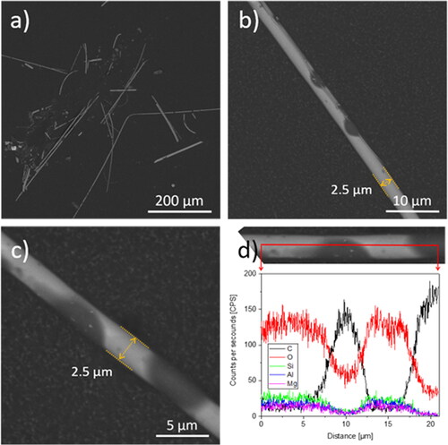
Figure 5. SEM image (BSE 5 kV) of sample GW-B, fibers collected on the filter using Method 2 (airflow rate 2 l/min): (a) collected fibers with random diameter distribution; (b)–(c) two fibers with diameter < 3 µm with dark areas of the organic material; (d) EDXS spectra showing a marked carbon peak and decrease in other elements levels corresponding to the dark spot position. The EDXS data was obtained from the same location as in (c).
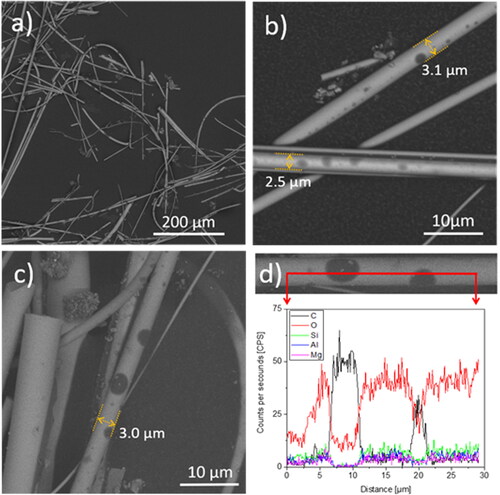
show SEM images of sample SW-C, GW-C, and SW-D, airborne fibers collected using Method 3 using a 13, 22, and 32 l/min air flow, respectively. Fibers with a diameter < 3 µm having binder spot areas on the surface are also observed in , and , . EDXS line scans presented in , and confirm the presence of the organic substance on the surface of the stone and glass fibers similar to samples SW-B and GW-B, collected using Method 2.
Figure 6. SEM image (BSE 5 kV) of sample SW-C, fibers collected on the filter using Method 3 (airflow rate of 13 l/min): (a) collected fibers with random diameter distribution; (b)–(c) two fibers with diameter < 3 µm with dark areas of the organic material; (d) EDXS spectra showing a marked carbon peak and decrease in other elements levels corresponding to the dark spot position. The EDXS data was obtained from the same location as in (c).
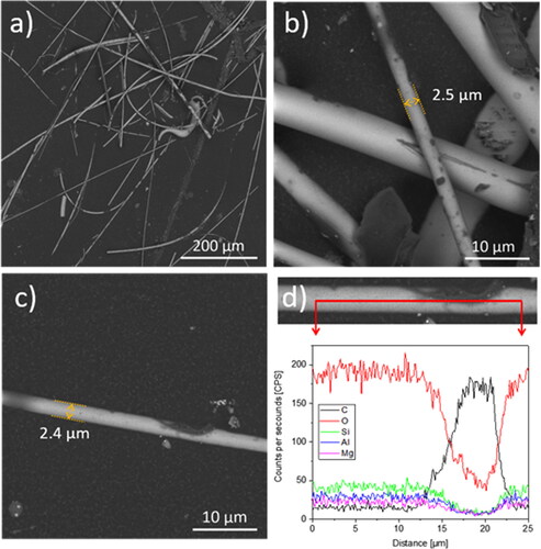
Figure 7. SEM image (BSE 5 kV) of sample GW-C, fibers collected on the filter using Method 3 (airflow rate of 22 l/min): (a) collected fibers with random diameter distribution; (b)–(c) two fibers with diameter < 3 µm with dark areas of the organic material; (d) EDXS spectra showing a marked carbon peak and decrease in other elements levels corresponding to the dark spot position. The EDXS data was obtained from the same location as in (c).
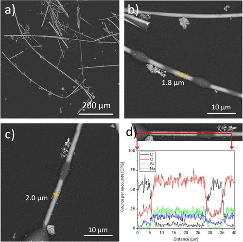
Figure 8. SEM image (BSE 5 kV) of sample SW-D, fibers collected on the filter using Method 3 (airflow rate of 32 l/min): (a) collected fibers with random diameter distribution; (b)–(c) two fibers with diameter < 3 µm with dark areas of the organic material; (d) EDXS spectra showing a marked carbon peak and decrease in other elements levels corresponding to the dark spot position. The EDXS data was obtained from the same location as in (c).
Discussion
The SEM images of the original fiber materials reveal the occurrence of dark droplets or dark irregular areas on the untreated fiber surfaces for both SW and GW ( and ). Individual droplets on the fiber surface or droplets with irregular shape glue the fibers together in different directions: with an angle or parallel to the fiber elongation as seen on the SEM images ( and ). This is consistent with the finding described in (Barly et al. Citation2019; Okhrimenko et al. Citation2022). The heat-treated fiber samples, SW-A and GW-A, show no agglomerations or droplets (, and and ). Thus, it seems reasonable to suggest that the dark areas on the surface of the fibers are composed of an organic material (binder) that was removed during the heat treatment carried out in this study.
From , it can be concluded that the binder material on the surface of respirable fibers seen as dark areas on the fibers are distributed similarly as on the surface of other, non-airborne, fibers shown in earlier work by Barly et al. (Citation2019) as well as in and . The major fraction of the binder material is deposited on fiber surfaces as droplets or irregularly as micrometer size deposits visible with SEM analysis, and a small fraction of the binder material can form a several nanometer thin incomplete layer, which only can be studied with surface sensitive techniques with nanometer probing analytical depth (Okhrimenko et al. Citation2018, Citation2022, Citation2023; Hirth et al. Citation2021). SEM observation of micrometer-sized droplets implies layer presence on the airborne respirable fibers similar to that on non-airborne fibers (Okhrimenko et al. Citation2018, Citation2022, Citation2023; Hirth et al. Citation2021), and therefore, we did not perform surface-sensitive analysis in nanometer scale on the collected airborne respirable fibers. A nanometer-scale organic layer is likely formed due to binder spreading on the fiber and also from applied mineral oil and organic contaminations of different origins (adventitious carbon). It should be noted that such a layer does not influence the dissolution of fibers as found by (Barly Citation2019; Okhrimenko et al. Citation2022) due to layer incompleteness (Okhrimenko et al. Citation2022, Citation2023).
In this study, the morphology of fibers that fulfill the WHO (IARC Citation2002) definition of being an airborne respirable fiber is investigated. Fibers that fulfill the definition of respirable according to the EN 481 (Method 1 using a cyclone) were not detected. However, for respirable fibers according to WHO (IARC Citation2002), two air flow rate regimes were used i.e., 2 l/min and ≥ 13 l/min, and for both flow regimes respirable fibers are observed with droplets of binder material or irregular coverage of binder material (). This shows that in a work situation, respirable fibers with binder could potentially reach the deep part of the lung. Therefore, the fact that some fibers with binders can potentially reach the deep part of the lung is already inherently included in the hazard assessment by IARC (IARC Citation1988, Citation2002; Baan and Grosse Citation2004), where part of the assessment includes comprehensive epidemiological studies addressing the cancer incidence and mortality among workers in the stone and glass wool production were made. WHO and IARC (IARC Citation2002) conclude that mineral wool fibers are “not classifiable” as to their carcinogenicity to humans as the evidence of carcinogenicity is “inadequate” in humans and “limited” in animals, this for both stone and glass wool.
Conclusions
Binder, which originates from mineral wool production, is found on airborne respirable fibers collected during professional installation of mineral wool products using methods according to either WHO (Citation1997) and ISO16000-7, or WHO (Citation1997) and MDHS 39/4 (Citation1995). SEM images and EDXS analysis showed that the organic material is deposited as discrete droplets of circular or elongated shape with a diameter < 3 µm and a length < 5 µm. The binder material does not form a thick uniform full coverage. Thus, despite respirable fibers that can reach the deep part of the lungs can potentially hold organic matter, they do not cause any hazardous response according to epidemiological studies. These findings suggest that the respirable fibers assessed in the IARC hazard assessments of stone and glass wool fibers (IARC Citation1988, Citation2002) may have also contained binder materials on the fibers.
Acknowledgments
Thanks to senior specialist Thomas Witterseh, Danish Technological Institute, Denmark for carrying out the respirable fiber sampling. Carpenter K. Nielsen for sample installation. Engineer S.H.Q. Barly and development Engineer J.A. Bøtner both ROCKWOOL A/S for sample characterization.
Conflict of interest
C. Koch was affiliated with ROCKWOOL A/S when the work was carried out. M. Solvang and D.V. Okhrimenko are employed by ROCKWOOL A/S. ROCKWOOL A/S is a stone wool manufacturer.
Data availability
The data that support the findings of this study are available from the corresponding author, MS, upon reasonable request.
Correction Statement
This article has been corrected with minor changes. These changes do not impact the academic content of the article.
Additional information
Funding
References
- Baan RA, Grosse Y. 2004. Man-made mineral (vitreous) fibres: evaluations of cancer hazards by the IARC monographs programme. Mutat Res. 553(1–2):43–58. doi:10.1016/j.mrfmmm.2004.06.019
- Barly SHQ, Okhrimenko DV, Solvang M, Yue Y, Stipp SLS. 2019. Dissolution of stone wool fibers with phenol-urea formaldehyde binder in a synthetic lung fluid. Chem Res Toxicol. 32(12):2398–2410. doi:10.1021/acs.chemrestox.9b00179
- Bauer JF. 1998. Interaction of glass fiber with physiological fluids: the role of surface. In: Proceeding of the 18th International Congress on Glass. Vol. C-05, San Francisco, CA: American Ceramic Society.
- Bellmann B, Schaeffer HA, Muhle H. 2010. Impact of variations in the chemical composition of vitreous mineral fibers on biopersistence in rat lungs and consequences for regulation. Inhalation Toxicol. 22(10):817–827. doi:10.3109/08958378.2010.483771.
- Bernstein DM. 2007. Synthetic vitreous fibers: a review toxicology, epidemiology and regulations. Crit Rev Toxicol. 37(10):839–886. doi:10.1080/10408440701524592.
- Brown JS. 2015. Deposition of particles. In: Parent RA, editor. Comparative biology of the normal lung. 2nd ed. USA: Elsevier Inc. p. 513–536. doi.: doi:10.1016/C2012-0-01154-4
- Campopiano A, Zakrzewska AM, Olori A, Cannizzaro A, Basili F, Ramires D. 2012. Glass fiber exposure assessment during ceiling installation by European Standard EN 689: Study of airborne fiber distribution. Atmos Pollut Res. 3(2):192–198. doi:10.5094/APR.2012.020.
- Christensen VR, Eastes W, Hamilton RD, Struss AW. 1993. Fiber diameter distribution in typical MMVF wool insulation products. Am Ind Hyg Assoc J. 54(5):232–238. doi:10.1080/15298669391354612
- EC. 2008. EC No 1272/2008 of the European Parliament and of the Council of 16 December 2008 on classification, labelling and packaging of substances and mixtures, amending and repealing Directives 67/548/EEC and 1999/45/EC, and amending. Official Journal of the European Union. L 353/1. ELI: http://data.europa.eu/eli/reg/2008/1272/oj.
- EN 481. 1993. Workplace atmospheres – size fraction definitions for measurement of airborne particles. Brussels: CEN.
- EN 689. 1995. Workplace atmospheres - Guidance for the assessment of exposure by inhalation to chemical agents for comparison with limit values and measurement strategy. Brussels: European Standard, ECS.
- Eastes W, Potter RM, Hadley JG. 2000. Estimating in vitro glass fiber dissolution rate from composition. Inhalation Toxicol. 12:269–280.
- Guldberg M, de Meringo A, Kamstrup O, Furtak H, Rossiter C. 2000. The development of glass and stone wool compositions with increased biosolubility. Regul Toxicol Pharm. 32(2):184–189. doi:10.1006/rtph.2000.1418
- Guldberg M, Jensen SL, Knudsen T, Steenberg T, Kamstrup O. 2002. High-alumina low-silica HT stone wool fibers: a chemical compositional range with high biosolubility. Regul Toxicol Pharm. 35(2):217–226. doi:10.1006/rtph.2001.1523
- Hirth S, Waindok H, Wohlleben W. 2021. Which fraction of stone wool fibre surface remains uncoated by binder? A detailed analysis by time-of-flight secondary ion mass spectrometry and X-ray photoelectron spectroscopy. RSC Adv. 11(62):39545–39552. doi:10.1039/d1ra06251d.
- Hjelmgaard T, Thorsen PA, Bøtner JA, Kaurin J, Schmucker CM, Nærum L. 2018. Towards greener stone shot and stone wool materials: binder systems based on gelatine modified with tannin or transglutaminase. Green Chem. 20(17):4102–4111. doi:10.1039/c8gc02021c.
- [IARC] International Agency for Research on Cancer. 1988. IARC monographs on the evaluation of carcinogenic risks to humans. Man-made mineral fibres and radon. Vol 43. Lyon, France: IARC Press.
- [IARC] International Agency for Research on Cancer. 2002. IARC Monographs on the evaluation of carcinogenic risks to humans. Man-made vitreous fibres. Vol. 81. Lyon, France: IARC Press.
- ISO 16000-7. 2007. Indoor air. Part 7: Sampling strategy for determination of airborne asbestos fibre concentrations. Geneva: ISO.
- Jacob TR, Hadley JG, Bender JR, Eastes W. 1993. Airborne glass fiber concentrations during manufacturing operations involving glass wool insulation. An Ind Hyg Assoc J. 54(6):320–326.
- Jimenez AS, van Tongeren M, Aitken RJ. 2012. Guidance for collection of inhalable and respirable Ni dust. In: Strategic Consulting: 538-0000. Edinburgh: IOM. doi:10.1080/15298669391354739
- Knudsen T, Guldberg M, Christensen VR, Jensen SL. 1996. New type of stonewool (HT fibres) with a high dissolution rate at pH = 4.5. Glass Sci Technol. 69(10):331–337.
- Koenig AR, Hamilton RD, Laskowski TE, Olson JR, Gordon JF, Christensen VR, Byers CD. 1993. Fiber diameter measurement of bulk man-made vitreous fiber. Anal Chem Acta. 280(2):289–298. doi:10.1016/0003-2670(93)85133-5
- Kowatsch S. 2010. Mineral wool insulation binder. In: Pilato L, ed. Phenolic resins: a century of progress. Berlin: Springer. p. 209–242.
- Marchant GE, Amen MA, Bullock CH, Carter CM, Johnson KA, Reynolds JW, Connelly FR, Crane AE. 2002. A synthetic vitreous fiber (SVF) occupational exposure database: implementing the SVF health and safety partnership program. Appl Occup Environ Hyg. 17(4):276–285. doi:10.1080/10473220252826583.
- Marchant GE, Connelly R, Crane A, Fayerweather W, Puhala E, Sandin K. 2021. Occupational exposure to glass wool fibers: an update. J Occup Environ Hyg. 18(4–5):212–221. doi:10.1080/15459624.2021.1901906.
- Maxim LD, Hadley JG, Potter RM, Niebo R. 2006. The role of fiber durability/biopersistence of silica-based synthetic vitreous fibers and their influence on toxicology. Regul Toxicol Pharmacol. 46(1):42–62. doi:10.1016/j.yrtph.2006.05.003.
- MDHS 39/4. 1995. Asbestos fibres in air. Health and Safety Laboratory. Sheffield: HSE.
- Oberdörster G. 2000. Determinants of the pathogenicity of man-made vitreous fibers (MMVF). Int Arch Occup Environ Health. 73(S1):S60–S68. doi:10.1007/PL00014628
- Okhrimenko DV, Thomsen AB, Ceccato M, Johansson DB, Lybye L, Bechgaard K, Tougaard S, Stipp, SLS. 2018. Impact of curing time on ageing and degradation of phenol-urea-formaldehyde binder. Polym Degrad Stabil. 152:86–94. doi:10.1016/j.polymdegradstab.2018.04.001
- Okhrimenko DV, Bøtner JA, Riis HK, Ceccato M, Foss M, Solvang M. 2022. The dissolution of stone wool fibers with sugar-based binder and oil in different synthetic lung fluid. Toxicol in Vitro. 78:105270. doi:10.1016/j.tiv.2021.105270.
- Okhrimenko DV, Ceccato M, Tougaard S, Foss M, Pezennec E, Solvang M. 2023. Comment on “Which fraction of stone wool fibre surface remains uncoated by binder? A detailed analysis by time-of-flight secondary ion mass spectroscopy and X-ray photoelectron spectroscopy”. RSC Adv. 11:39545. doi:10.1039/D2RA07959C.
- M, Perininger R, Zoitos B, Boymel P, Steenberg T, Madsen AL, Guldberg M. 2002. EURIMA test guideline: in-vitro acellular dissolution of man-made vitreous silicate fibres. Glass Sci Technol. 75(5):263–270.
- Potter RM, Olang N. 2013. The effect of a new formaldehyde-free binder on the dissolution rate of glass wool fibre in physiological saline solution. Part Fibre Toxicol. 10:13. doi:10.1186/1743-8977-10-13.
- Sauer UG, Werle K, Waindok H, Hirth S, Hachmöller O, Wohlleben W. 2021. Critical choice in predicting stone wool biodurability: lysosomal fluid compositions and binder effect. Chem Res Toxicol. 34(3):780–792. doi:10.1021/acs.chemrestox.0c00401.
- SCOEL. 2011. Recommendation from the scientific committee on occupational exposure limits for refractory ceramic fibres. Brussels, Belgium: European Commission. Employment, Social Affairs and Inclusion.
- Sebastian K, Fellman J, Potter RM, Bauer J, Searl A, de Meringo A, Maquin B, de Reydellet A, Jubb G. Moore M., et al 2002. EURIMA test guideline: in-vitro acellular dissolution of man-made vitreous silicate fibres. Glass Sci Technol. 75(5):263–270.
- Wohlleben W, Waindok H, Daumann B, Werle K, Drum M, Egenolf H. 2017. Composition, respirable fraction and dissolution rate of 24 stone wool MMVF with their Binder. Part Fibre Toxicol. 14(1):29. doi:10.1186/s12989-017-0210-8.
- [WHO] World Health Organisation. 1997. Determination of airborne fibre number concentrations. A recommended method, by phase-contrast optical microscopy (membrane filter method). Geneva: World Health Organization. https://apps.who.int/iris/handle/10665/41904.
- [WHO] World Health Organisation. Occupational and Environmental Health Team. 1999. Hazard prevention and control in the work environment airborne dust. Geneva: World Health Organization. https://apps.who.int/iris/handle/10665/66147.
- Yue Y, Solvang M. 2021. Stone and glass wool. In: Richet P, editor. Encyclopedia of glass science, technology, history, and culture. Vol. 2. Hoboken (NJ): John Wiley & Sons, Inc. p. 1103–1111.
- Zu Q, Solvang M, Li H. 2021. Commercial glass fibers. In: Li H, editor. Fiberglass science and technology. Vol. 1. Switzerland: Springer Nature. p. 1–87.