ABSTRACT
Patch grafts are widely used in various kind of vascular surgeries such as detect repair or dilation of vascular stenosis. Expanded polytetrafluoroethylene (ePTFE) patches are flexible and handle well, but have shown problems with calcification as they are non-bioabsorbable and therefore permanently remain in the body. It is important to develop an alternative biocompatible patch. Silk fibroin (SF) was developed as a biocompatible material, but it lacks of the elasticity required for surgery as a patch. Polyurethane (PU) is also a well-known elastomer so this study focused on the SF and the PU blend materials with a weight ratio of 5:5 (SF/PU). To evaluate the SF/PU patch, the patches were implanted into the abdominal aortas of rats, using the ePTFE patch in the control group. Because it was more flexible the SF/PU patch was easier to implant than the ePTFE patch. At 1 week after implantation, the SF/PU patch had been infiltrated with cells and collagen fiber. The ePTFE control patch did not accumulate collagen fiber until 3 months and calcification occurred at 4 weeks. The SF/PU patch did not present any signs of calcification for 3 months. This study addressed the problems associated with using SF in isolation and showed that the SF/PU patch can be considered as a useful alternative to the ePTFE to overcome the problem of calcification.
INTRODUCTION
A patch graft is a kind of medical sheet device developed for the treatment of certain vascular diseases such as defect repair and stenosis dilation. Although the expanded polytetrafluoroethylene (ePTFE) patches dominate in the patch graft industry, these patches are associated with some complications like thrombus formation and patch calcification.Citation1 Because the patches are non-bioabsorbableCitation2 they consequently remain in the body as foreign matters causing some problems. Moreover the implanted patch is non-degradable and inhibits the growth of the blood vessels. Patients who experience these complications sometimes require reoperation to replace the graft. To resolve these problems, the development of new patch grafts familiar to vessels is imperative.
The important characteristics are required for optimal patch grafts. Firstly, the patch includes the flexibility to support blood pressure and good handling. Because the ePTFE patch has these characteristics already the new patch should have at least the same flexibility. Secondly, the biocompatibility is needed to integrate with a patch and native tissue. This future has the potential to cause biodegradation for the patch. However excessive reaction caused inflammation, stenosis and collapse of the vessel. It is better for the patch to replace with native tissue because it is still a foreign matter. Moreover the degrade speed was suggested to be important for biocompatibility. Finally is the non-calcification. It is a major problem of ePTFE patch. Recent studies have been shown the application of tissue engineering techniques in the development of biomedical devices.Citation3,4,5A wide variety of studies have focused on tissue engineering, but until now the development of a patch graft containing required characteristics has been still unsuccessful. This study selected an electro-spinning method because it was suggested to form a non-woven fabric patch that regenerative cells could easily infiltrate.Citation5,6
In this study, silk fibroin (SF) and polyurethane (PU) were focused for new biocompatible patch. SF is a fibrous protein that removed sericin from bombyx mori silk thread for medical materials. Silk fibroin (SF) was focused as a medical material such as a filmCitation7, hydrogelsCitation8 and a sheet Citation9 of multiple purposes. In previous reports, processed SF materials had shown the information, and it also suitable for many kinds of organs including vascular.Citation10 Moreover SF has the high biocompatibility and slow biodegradation.Citation11-13 It had been shown in rat abdominal aortas that small artificial vascular grafts made from SF effectively dissolved and was replaced with native tissue.Citation14 Therefore, we selected SF as the base material to develop a biocompatible patch. However in our previous study showed that, SF patch was difficult to implant after autoclave because it became too hard and fragile to mold or suture. Polyurethane (PU) is the general term for polymer compounds which are widely used as adhesives or clothes. They have high flexibility and drug resistance. A previous study had developed a non-woven SF and PU blend sheet from a polymer solution. It had shown to be highly miscible SF and PU, to maintain SF useful structure, and that it suggested to mix PU with SF to improve flexibility while largely maintaining tensile strength. Citation15 From this result, PU was selected to improve the flexibility of SF patch.
In this study, an SF/PU patch was engineered by an electro-spinning method as a non-woven sheet and investigated the response to native vessels in vivo. This patch was evaluated on the bases of its flexibility from PU, biocompatibility from SF, and calcification comparing with the control group (ePTFE patch).
RESULTS
Patch implantation
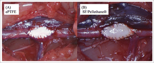
During the implantation process, the ePTFE patch was too soft to cut into an elliptical shape under a light microscope, and blood leaked from the suture sites between native vessel and the patch and the needle hole. Consequently, operation took longer time than SF/PU patch. The SF/PU patch preserved in saline solution was moderately soft and easy to cut. There were not any problems for implantation comparing to ePTFE patch. Beneficial characteristics of the SF/PU patch include good handling, convenient implantation, reduced operation time, and no bleeding at the suture sites. showed both patches after implantation. All rats survived throughout the period of experiment until autopsy was performed in all groups.
Histological and immunohistochemical evaluation
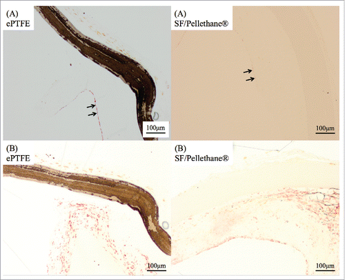
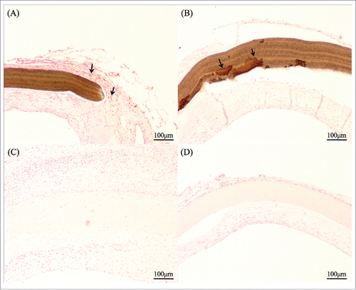
Inflammation was observed in both patches. In the first two weeks, neutrophils and macrophages had migrated to the site at both patches. Excessive inflammation was not observed in all samples though. The distinctive reactions of ePTFE patches were shown in . ePTFE patches can cause many clot (21 samples/30 samples). SF/PU patches caused fibroblast infiltration, macrophages as well as multinucleated giant cells. At 3 months, inflammation of tissue surrounding the patch had subsided. A new layer comprising collagen fiber, fibroblasts and various other cells was found on the luminal face of the patches in all samples (). It also appeared that the collagen layer integrated continuously onto the native vessel. During sampling, the ePTFE patches appeared to easily separate from and lose this layer, while SF/PU patches were easy to cut with surroundings tissue showing an insignificant boundary line between original and new cell layers, which had naturally attached to surrounding tissues. showed scoring evaluation of cell reaction, inflammation and infiltration, by HE staining. Both patches, inflammation decreased at 3 month. Infiltration was not shown in all ePTFE patches. showed scoring evaluation of collagen fiber, layer formation and infiltration, by MTC staining. Layer formation was gradually completed in both patches. Infiltration was not shown at every ePTFE patches.
FIGURE 2. (A) This figure was stained by MTC method. A 1-week sample from the control group revealed a clot between the ePTFE patch and its surrounding tissue. (B) After 3 weeks, inflammation cells and native tissue became non-reactive to ePTFE patches.
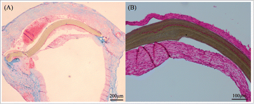
FIGURE 3. This figure was shown samples of 3 months. SF/Pellethane® patch was stained by HE method (A) and shown collagen fibers in blue color by MTC staining (B). ePTFE patch was showed separation from the tissue (C) and was not infiltrated by collagen fibers (D).
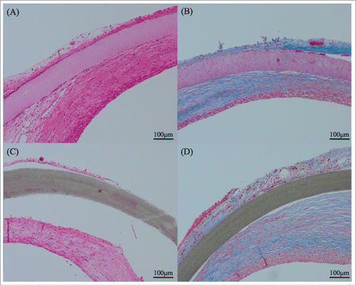
TABLE 1. Scoring of inflammation was done as follows; – (0), no; + (1), minute; ++ (2), modulate; +++ (3), severe and ± standard deviation (SD). Scoring of infiltration was done as follows; – (0), no; + (1), around patch; ++ (2), partial; +++ (3), overall and ± SD
TABLE 2. MTC staining results. Scoring of infiltration of collagen fibers was done as follows; – (0), no; + (1), a few or around patch; ++ (2), partial; +++ (3), overall and ± SD
Calcification was observed in ePTFE patches more than SF/PU patches (). The ePTFE patch was presented calcification deposits around it at 4 weeks. Moreover, at 3 months almost ePTFE patch was occurred severe calcification itself (). Conversely, calcification of SF/PU patches themselves was not observed, there were only deposits around them in both periods of experiment.
TABLE 3. Scoring of calcification was done as follows; – (0), no; + (1), calcification deposits around patch; ++ (2), in patch; +++ (3), severe and ± SD
FIGURE 4. Kossa staining indicated calcification in brownish color. (A) ePTFE patch at 4 weeks had some calcified granules. (B) At 3 months, the calcification of the all ePTFE patch itself was observed. (C) SF/Pellethane® patches at a few samples had calcified granules. (D) At 3 months almost samples had only granules and did not react patch itself.
Immunohistochemical evaluation showed no differences between experimental and control patches ()
DISCUSSION
The ePTFE patch is non-water absorbent and stable not to change in the body. After suturing the ePTFE patch needle holes remain open, causing significant bleeding. The structure of SF make it highly water-absorbent; it becomes swollen after implantation and the needle holes are spontaneously closed. SF is however difficult to handle in the implantation process, too stiff to attach to the vessel and fragile enough to be torn by sutures. These problems were resolved by mixing SF with PU. This study revealed that the SF/PU patch was easy to handle compared with the ePTFE patch. Minimal bleeding made a clear operative field and the patch did not rupture and split, potentially decreasing surgical time.
The ePTFE patch is currently widely used as stable material, however sometimes it caused complications in vascular surgery. Citation16 Thrombus formations needed the treatment of anticoagulantsCitation17, and in this study thromogenicity of ePTFE patch was described. Moreover, its biostability was understood as advantages and disadvantages depending on the cases.Citation18,19 In this study, its characteristic was happened to easy separate from surrounding tissues during dissection, whereas SF/PU patches can merge with surrounding tissue. This difference of patches was showed the difference of its biocompatibility. SF/PU patch also showed continuously increased cellular reactions to patches. Although further immunostaining is needed for classification of the cells, inflammatory cells or phagocytes infiltrated into the patch may consider caused by the biodegradability of SF.Citation20 The SF/PU patch showed infiltration of collagen fiber, which was not observed in ePTFE patches. Infiltration described the integration with surrounding tissues, and it suggested the materials might have the biodegradability. In this study, SF/PU patch was considered with starting to degrade in 4 weeks because they showed infiltrations at 4 week. On the other hand, ePTFE patch was considered not biodegradable because there were no infiltrations. According to these histologic results, SF/PU patches had seen the less excessive tissue reactions such as thrombosis formation or separation from tissues because it promoted to integrate with native vessel. Therefore, it was suggested that SF/PU patch was biocompatible; an essential characteristic for developing an efficient patch graft.
The immunostaining result of SF/PU and ePTFE patches showed a similar tissue reaction. In both groups, vessel-like structures of smooth muscle and endothelial cells were created under the patches. The alignment of collagenous fiber and smooth muscle cells was very similar to the middle coat of the artery. Moreover this innermost layer consisted of endothelial cells physiologically to release a vasoactive substance, contract and relax vessel wall, adjust coagulation fibrinolysis systems. By these results of immunostaining, the patch might be degraded in the future, but the vascular like structure will be maintained to act as a new vessel.
In addition to this superior tissue affinity the study also focused on the anti-calcification feature of SF/PU compared with the ePTFE patch. Calcification is the most frequent cause of clinical failure of bioprosthetic tissues and polymeric biomaterials, but the mechanism is not yet elucidated. Calcification is usually known as a medium- to long-term complication after implantation. In the present study, we found notable differences in calcification between the experimental and control groups at 4 weeks and 3 months. The SF/PU patch showed a hypocalcification quality superior to the ePTFE patch.
This study suggested that the ePTFE patch would remain as foreign matter because it did not occur the infiltration of cells and collagen fiber. In addition to this, calcification would process more severe. Conversely the SF/PU patch would be more infiltrated from surrounding tissue and might be replaced with native tissue. However because calcification deposits were observed the SF/PU patch had the possibility of remaining as foreign matter. Therefore long-term observation should be needed.
The ePTFE patches were not spun using the electro-spinning method, so in this study SF/Pellethane® patches were compared with “commercial products”. We should study how about the electro-spinning ePTFE patch.
This study highlighted the advantages of SF/PU patches, which included good biological compatibility and facilitating tissue infiltration and biodegradability. PU added the dynamic intensity and flexibility to the patches. The overall handling of the SF/PU patch was also excellent and mitigated bleeding. Furthermore, anti-calcification features were significantly superior to the ePTFE patches.
CONCLUSION
In this study, we engineered an SF/PU blend material was engineered with improvedflexibility and tensile strength compared to ePTFE. Although it was moderate, the SF/PU patch promoted native tissue infiltration and conquered the calcification problem which is the most detrimental disadvantage of the ePTFE patch. Although further development and improvements are necessary, the SF/PU patch shows much promise as an alternative and superior new degradable patch graft.
MATERIALS AND METHOD
Patch preparation
Firstly, silk fiber was obtained from a silk thread reeled and degummed cocoons of Bombyx mori.Citation10 The SF fiber was dissolved in 9 M LiBr, and then this solution was dialyzed against distilled water to completely remove the LiBr according to a previous study.Citation21 Its solution was centrifuged to remove insoluble materials and to extract SF aqueous solution. After centrifuge, SF sponge was fabricated by freeze-drying the 1% (w/v) SF aqueous solution.
Secondly, the medical PU, Pellethane® (2363–80AE, DOW chemical), and SF sponge at a 5:5 weight ratio were dissolved in 1,1,1,3,3,3-hexafluoro-2-propanol solution (6%(w/v)) (Wako Pure Chemical Industries, Ltd). SF/PU patches of 100 μm were spun from this solution using the electro-spinning method at an injection speed of 12 μL/min and applied voltage of 16 kV. After spinning, the patches were incubated for 24 hours at 37°C and 100% humidity to convert the structure of SF into insoluble form. The patches were finally sterilized by autoclaving at 121°C. For patch implantation, patches were shaped elliptically (width 3 mm, length 6 mm, thickness 100 μm). In this study, the ePTFE patch (Gore-tex®, GORETEX Japan) was used as the control to make a comparison with SF/PU patch. This patch preparation process was accorded to our previous study.Citation22 The SF/PU patch and the ePTFE patch were used for five groups (1 week, 2 weeks, 3 weeks, 4 weeks and 3 months), and each groups had six rats.
Animals
Sixty adult male Sprague-Dawley (SD) rats (250–350 g) (Charles River Laboratories) were used. All experimental procedures and protocols were approved by Tokyo University of Agriculture and Technology (TUAT) (Approval number: 26–92), and rats were managed and cared for in accordance with the standards established by TUAT and described in “Guide for the Care and Use of Laboratory Animals”.
Patch implantation
Rats were anesthetized by intraperitoneal injection of pentobarbital (50 mg/kg) (Somnopentyl, Kyoritsu Seiyaku Co.). After that abdominal area was prepared for surgery, median incision was created. The abdominal aorta was exposed and separated carefully from the vein. The aortic branches in this segment were ligated by bipolar. A little bleeding was stopped by compression technique. The proximal and distal portions of the ventral aorta were clamped with two vascular clips (Micro series disposable micro vascular clip TKL-2–60, BEAR Medic Corporation). The part of the aorta between the two clips (about 1 cm) was cut in the transverse, and then the patch was implanted and sutured with continuous 9–0 monofilament nylon sutures (No.8, BEAR Medic Corporation). At this time, full layer suturing was performed so as not to damage the native blood vessel as much as possible. Both curves of the ellipse required 6–8 stitches. After the implanted patch was rechecked for blood leakage, the distal and proximal vascular clamps were slowly removed. If blood leakage did not stop by compression or coagulation, additional suturing (1 or 2 single suture) was performed. All implantation procedures were performed under microscope (M60, Leica Microsystems). Total clamp time was 30–45 min approximately. Finally, orbifloxacin 0.5 mg/kg (VICTAS®Injection-5%, Kyoritsu Seiyaku Co.) was injected into the abdominal cavity, and the incision site was closed with single 3–0 monofilament nylon sutures. All rats were completely recovered from anesthesia. After operation all experimental rats were taken care of same as normal rats.
Histological and immunohistochemical evaluation
At weeks 1–4 and at 3 months after patch implantation, rats were anesthetized with pentobarbital injection (50 mg/kg) and the abdomen was incised to expose the implanted area. The ventral aorta and the implanted patch were evaluated for gross appearance. Rats were then perfused with 0.9% saline solution (HIKARI, Hikari pharmaceutical Co.) through the left ventricle. The patches were carefully removed from the surrounding tissue. Samples were embedded by paraffin and processed for hematoxylin and eosin (HE) staining and Masson trichrome (MTC) staining. HE staining was used to observe the structure of samples and check the inflammation and cell infiltration. MTC staining was used to detect collagen fiber surround patch site. Only samples taken at 4 weeks and 3 months were Kossa stained to observe calcification. The 4 -weeks samples were processed for immunohistochemical staining with primary antibodies, CD31 (50-fold dilution) (clone TLD-3A12, LifeSpan BioSciences Inc.) and α-smooth muscle actin (clone 1A4, Nichirei Biosciences Inc.). Immunostaining was performed to observe a migration of endothelial cells (CD31) and a formation of smooth muscle layer (αSMA).
The evaluation of samples
Scoring of inflammation was subcategorized into 4 groups as follow: each group was evaluated by the migration of inflammation cells such as neutrophils and macrophages. Firstly; minus group, – (0) there was no appearance of inflammation cells. Secondly; one plus group, + (1) there was a partial inflammation, which was under 10 cells per 100x object power lens. Thirdly; two plus group, ++ (2) there was overall, which was 10–19 cells per 100x object power lens, and finally; three plus group, +++ (3) there was severe inflammation, which was over 20 cells per 100x object power lens.
Infiltration of cells and collagen fibers was roughly classified for 4 groups. Firstly; minus group, – (0) there was no appearance of cells and fibers. Secondly; one plus group, + (1) there was cell and fiber migration at the patch boundary. Thirdly; two plus group, ++ (2) there was cell and fiber infiltration on the edge of the patch and finally; three plus group, +++ (3) there was into center of the patch.
Layer formation was scored by the structures of the luminal layer under the patch as 4 groups. Firstly; minus group, – (0) there was no layer. Secondly; one plus group, + (1) there was an irregular cell layer. Thirdly; two plus group, ++ (2) there was a layer of collagen fiber, and finally; three plus group, +++ (3) there was a clear layer such as tunica media.
Disclosure of Potential Conflicts of Interest
No potential conflicts of interest were disclosed.
Funding
This work was supported by the Science and technology research promotion program for agriculture, forestry, fisheries and food industry under Grant 26051A.
Reference
- Hayabuchi Y, Mori K, Kitagawa T, Sakata M, Kagami S. Polytetrafluoroethylene graft calcification in patients with surgically repaired congenital heart disease: evaluation using multidetector-row computed tomography. Am Heart J. 2007;153:806 e1-8. doi:10.1016/j.ahj.2007.01.035
- Scott TA, Towle HJ, Assad DA, Nicoll BK. Comparison of bioabsorbable laminar bone membrane and non-resorbable ePTFE membrane in mandibular furcations. J Periodontol. 1997;68:679-86. doi:10.1902/jop.1997.68.7.679
- Qazi TH, Rai R, Dippold D, Roether JE, Schubert DW, Rosellini E, Barbani N, Boccaccini AR. Development and characterization of novel electrically conductive PANI-PGS composites for cardiac tissue engineering applications. Acta Biomater. 2014;10:2434-45. doi:10.1016/j.actbio.2014.02.023
- Pok S, Myers JD, Madihally SV, Jacot JG. A multilayered scaffold of a chitosan and gelatin hydrogel supported by a PCL core for cardiac tissue engineering. Acta Biomater. 2013;9:5630-42. doi:10.1016/j.actbio.2012.10.032
- Mukherjee S, Gualandi C, Focarete ML, Ravichandran R, Venugopal JR, Raghunath M, Ramakrishna S. Elastomeric electrospun scaffolds of poly(L-lactide-co-trimethylene carbonate) for myocardial tissue engineering. J Mater Sci Mater Med. 2011;22:1689-99. doi:10.1007/s10856-011-4351-2
- Prabhakaran MP, Nair AS, Kai D, Ramakrishna S. Electrospun composite scaffolds containing poly(octanediol-co-citrate) for cardiac tissue engineering. Biopolymers. 2012;97:529-38. doi:10.1002/bip.22035
- Jin HJ, Park J, Valluzzi R, Cebe P, Kaplan DL. Biomaterial films of Bombyx mori silk fibroin with poly(ethylene oxide). Biomacromolecules. 2004;5:711-7. doi:10.1021/bm0343287
- Kapoor S, Kundu SC. Silk protein-based hydrogels: Promising advanced materials for biomedical applications. Acta Biomater. 2016;31:17-32. doi:10.1016/j.actbio.2015.11.034
- Li M, Ogiso M, Minoura N. Enzymatic degradation behavior of porous silk fibroin sheets. Biomaterials. 2003;24:357-65. doi:10.1016/S0142-9612(02)00326-5
- Kundu B, Rajkhowa R, Kundu SC, Wang X. Silk fibroin biomaterials for tissue regenerations. Adv Drug Del Rev. 2013;65:457-70. doi:10.1016/j.addr.2012.09.043
- Asakura T, Suzuki Y, Nakazawa Y, Yazawa K, Holland GP, Yarger JL. Silk structure studied with nuclear magnetic resonance. Prog Nucl Magn Reson Spectrosc. 2013;69:23-68. doi:10.1016/j.pnmrs.2012.08.001
- Vepari C, Kaplan DL. Silk as a biomaterial. Prog Polym Sci. 2007;32:991-1007. doi:10.1016/j.progpolymsci.2007.05.013
- Leal-Egana A, Scheibel T. Silk-based materials for biomedical applications. Biotechnol Appl Bioc. 2010;55:155-67. doi:10.1042/BA20090229
- Enomoto S, Sumi M, Kajimoto K, Nakazawa Y, Takahashi R, Takabayashi C, Asakura T, Sata M. Long-term patency of small-diameter vascular graft made from fibroin, a silk-based biodegradable material. J Vasc Surg. 2010;51:155-64. doi:10.1016/j.jvs.2009.09.005
- Nakazawa Y, Asano A, Nakazawa CT, Tsukatani T, Asakura T. Structural characterization of silk-polyurethane composite material for biomaterials using solid-state NMR. Polym J. 2012;44:802-7. doi:10.1038/pj.2012.119
- Jenkins AM, Buist TA, Glover SD. Medium-term follow-up of forty autogenous vein and forty polytetrafluoroethylene (Gore-Tex) grafts for vascular access. Surgery. 1980;88:667-72.
- Begovac PC, Thomson RC, Fisher JL, Hughson A, Gallhagen A. Improvements in GORE-TEX vascular graft performance by Carmeda BioActive surface heparin immobilization. European journal of vascular and endovascular surgery: the official journal of the European Society for Vascular Surgery. 2003;25:432-7. doi:10.1053/ejvs.2002.1909
- Huang WJ, Hu FR, Chang SW. Clinicopathologic study of Gore-Tex patch graft in corneoscleral surgery. Cornea. 1994;13:82-6. doi:10.1097/00003226-199401000-00015
- Neel HB, 3rd. Implants of Gore-Tex. Archives of Otolaryngology. 1983;109:427-33. doi:10.1001/archotol.1983.00800210003001
- Santin M, Motta A, Freddi G, Cannas M. In vitro evaluation of the inflammatory potential of the silk fibroin. J Biomed Mater Res. 1999;46:382-9. doi:10.1002/(SICI)1097-4636(19990905)46:3<382::AID-JBM11>3.0.CO;2-R
- Aytemiz D, Sakiyama W, Suzuki Y, Nakaizumi N, Tanaka R, Ogawa Y, Ogawa Y, Takagi Y, Nakazawa Y, Asakura T. Small-diameter silk vascular grafts (3 mm diameter) with a double-raschel knitted silk tube coated with silk fibroin sponge. Adv Healthc Mater. 2013;2:361-8. doi:10.1002/adhm.201200227
- Nakazawa CT, Higuchi A, Asano A, Kameda T, Aytemiz D, Nakazawa Y. Solid-state NMR studies for the development of non-woven biomaterials based on silk fibroin and polyurethane. Polym J. 2017. doi:10.1038/pj.2017.16

