
 ?Mathematical formulae have been encoded as MathML and are displayed in this HTML version using MathJax in order to improve their display. Uncheck the box to turn MathJax off. This feature requires Javascript. Click on a formula to zoom.
ABSTRACT
On the basis of a circular bipolar plate (BP) of the proton exchange membrane fuel cell (PEMFC), a new rim-type radial flow field (FF) structure was designed inspired by the rim style of the vehicle. In this type of FF structure, the key variables are the number of layers of annular flow FFs, the number of branched FFs, and the amplitude of the waveform of branched FFs. To compare the effects of these variables on FF (especially the FF of cathode), the PEMFC single-cell model with different variables was developed by COMSOL Multiphysics software and then simulated. The reasonable value of these variables in enhancing the PEMFC performance was finally determined by comparing the oxygen distribution, water distribution, pressure drop on the cathode side, and the fuel cell output voltage and power of different schemes. This study achieves the highest ultimate current density and maximum power density among all schemes when the number of branches is 8. A four-layer structure is the most appropriate for selecting the number of FF layers. For the selection of the curvature of the branch, 15° is the most appropriate.
Introduction
To alleviate the problem of air pollution, many countries and enterprises have issued plans to stop selling internal combustion engine vehicles in the future. Among the many new energy machines that have been launched, fuel cells are favored by researchers and institutions in various countries. The fuel cell can directly convert chemical energy into electrical energy, which is not limited by the Carnot cycle effect. It uses fuel and oxygen as reactants, has no mechanical transmission parts and has the characteristics of high efficiency and no air-pollution. Among several kind of fuel cells, the PEMFC has high heating capacity because of its features of low working temperature, no air-pollution, high stability of work.
The BP, the key component of PEMFC, not only plays a huge key in electron conduction, but also undertake the support of cell mechanics. The use of COMSOL multiphysics software (Sezgin et al. Citation2016) for modeling and multiphysical field coupling simulation analysis can not only save the experiment and production cost but also obtain the simulation data that match the actual experimental data because the FF structure design of fuel cell is complex and the production cost is high. He (He et al. Citation2020)Respectively used back propagation neural network (BPNN) and adapted neural fuzzy inference system (ANFIS) to study the influence of historical behavior and operation mode of PEMFC on the static and non-static performance of PEMFC. These results are helpful to select appropriate parameters for predictive analysis in practical PEMFC applications, because it may experience complex operating conditions. Laribi (Laribi et al. Citation2021) develop a new diagnostic technique to determine the hydration status of the proton-exchange membrane fuel cell (PEMFC). To obtain more accurate parameters, Selem (Selem, Hasanien, and El Fergany Citation2020) and others designed a newly developed bionic manta ray foraging optimizer (MRFO), which can reliably and accurately extract the model uncertain parameters of PEMFCs (PEMFCs). In addition to the improvement of the traditional parallel direct current channel (Atyabi and Afshari Citation2019; Niu et al. Citation2018; Sadeghifar, Torkavannejad, and Pourmahmoud Citation2018; Timurkutluk and Chowdhury Citation2018; Xu et al. Citation2019) and serpentine channel (Jia, Sunden, and Xie Citation2019; Marappan et al. Citation2021), many designs and optimizations for the radial FF on the circular BP in recent years have been introduced. Compared with the traditional FF, the reaction gas in the radial FF of a circular BP enters from the central inlet, diffuses along the circumference of the surrounding FF and finally discharges from the edge of the FF. Zhu (Zhu and Zheng Citation2019) designed a new type of PEMFC radial FF, and found that the current density and power density of the radial FF were higher than those of the traditional FF. Solati (Solati et al. Citation2019) et al. designed four-channel radial (R4C), two-channel radial membrane electrode assembly (MEA) and horizontal MEA (R2CH), two-channel radial and vertical MEA (R2CV) structures and conventional fuel cells. The Computational Fluid Dynamics (CFD) model simulation and comparison test indicate that the net power of R4C is 42% higher than that of the basic model, and the R2CV is 8% lower than that of the basic model. Yutao, L (Yutao and Minggang Citation2021). et al designed a new PEMFC with an annular BP. The numerical simulation analysis and experimental verification and comparison indicate that the current density, hydrophobic performance and reaction gas distribution of the radial channel with an annular BP are better than those of the traditional model, and the peak power of the four-way serpentine FF is increased by 30%. Xie, Q (Xie Citation2021). and others mentioned a radial FF design structure of circular BP in PEMFC. The reaction gas enters from the central hole and diffuses around, and the reaction gas enters the next level of the rib plate from the holes on the rib plate. The number of rib plates and the number and arrangement of holes on the rib plate can change the performance results of different models. This finding indicates that the circular BP with a five-rib porous structure is more conducive to the performance of PEMFC. The peak efficiency is 10% higher than that of the new radial channel with an annular BP. Perez – Raya (Perez-Raya et al. Citation2010) and others designed a new FF of PEMFC using Cano geometry and triangular geometry. Simulation experiments indicate that the triangular geometry makes better use of the reaction area, and the power density is 50% higher than that of the Cano geometry model. Through the discovery and analysis of the above relevant literature, although the research on the radial FF of PEMFC has made some progress, many challenges still exist.
In addition to the radial FF, another type of FF with better development prospects is the bionic FF. Zhang (Zhang et al. Citation2022) analyzed the advantages and disadvantages of four types bio-inspired FFs, leaf, lung, tree leaf, lung, tree, and unconventional shape. Through experimental verification, the new FF branch structure shows similar performance to the parallel FF and achieves the most stable and highest power output through the serpentine FF. The common bionic models are leaf vein and lung models (Asadzade and Shamloo Citation2017; Dang and Zhou Citation2022). The numerical simulation and experimental tests indicate that leaf vein and lung FFs can effectively inhibit the inlet pressure drop, enable a more uniform reaction gas diffusion and improve the power density of the fuel cell. Yutao, L (Lian, Qz, and Mg Citation2020). et al. designed a PEMFC model with bionic vein structure. The CFD model simulation and experimental verification show that the included angle of 15–30° is the best for the hydrophobic performance and uniform distribution of reactants of the model. When the fuel cell with a bionic vein structure works at high power density, the included angle of 25° is the best. Ghadhban (Ghadhban, Alawee, and Dhahad Citation2021) et al. designed two new PEMFC FFs: vein and tree. A graphite model is developed and compared with the single snake FF. The result shows that the performance of the vein FF is 5.12% higher than that of the single snake FF and 3.75% higher than that of the tree FF. Li Yu-Ting (Yu-Ting, Gui, and Yuan-Yuan Citation2020) and others designed a new bionic PEMFC with a bionic snowflake shape. The construction of the CFD model and numerical simulation analysis indicates that the pressure drop performance, reaction gas diffusion, hydrophobic performance, and current density of the snowflake-like FF are better than those of the double serpentine FF, and the peak power density is 1.45 times that of the double serpentine FF. Qizhen Xie (Xie and Zheng Citation2021) et al. put forward the spider web type FF. It has higher electrochemical properties than the radial FF, which was close to the serpentine FF, but the pressure drop was much less than the serpentine FF, confirming the feasibility of the bionic cathode FF channel of the spider web structure. According to the sorting and analysis of the above literature, lungs and veins are common bionic objects, and many other similar substances in nature can be simulated.
In this study, after sufficient collection and comparison of natural or man-made substances, a new rim-type radial FF structure was designed by integrating the shape characteristics of the rim of a car tire with a radial FF on circular BPs. This structure has a multilayer annular FF as the main body, and adjacent annular FFs are connected by a branched FF extending from inlet to outlet. The branched FF adopts a wave-like design with a complete waveform between two adjacent annular FFs, and the peaks of the adjacent waveform face in opposite directions. In this type of structure, the number of layers of annular FFs, the number of branched FFs and the amplitude of the waveform of branched FFs are key variables. This study investigates their influence laws on the output performance of the cathode side of PEMFC and finally determines the reasonable values of these variables in improving the fuel cell performance.
Numerical model and method
Modeling
The rim in a vehicle plays the role of supporting tires and filtering road vibration and generally has high rigidity and toughness. With the development of the automobile industry, the focus has been on the overall aesthetics of the rim, and in this case, many rims with strange shapes have been designed. Inspired by various complex rim structures, this study attempts to combine them with radial FFs to design a new FF structure, as shown in . The number of layers of the annular channel, the number of branch channels, and the amplitude of the waveform of the branch channel (α) are the key parameters to determine the performance of this structure. In this study, a complete PEMFC monomer model with different variables is developed by COMSOL Multiphysics software, and its characteristics in different aspects, such as oxygen distribution, water distribution, voltage drop, and cell output voltage, are compared and analyzed. shows the computational domain of the model, whereas lists the main geometric parameters of the reference.
Figure 1. Rim-Type radial FF structure.
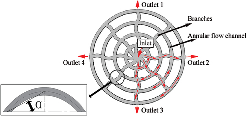
Figure 2. Computational domain of the rim-type radial FF model.
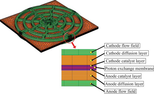
Table 1. Main geometrical parameters.
Governing equations
The mathematical model of PEMFC involves many disciplines, which follow the conservation laws of mass conservation, momentum conservation, component conservation, and charge conservation. The general formula of these conservation laws can be expressed by formula (1), as follows:
where ρ is the fluid density (kg/m3); ψ is the solving variable; t is time (s); is the velocity vector (m·s−1); Γ is the generalized diffusion coefficient, and Sψ corresponds to the source item of ψ.
The four terms in Equationequation (1)(1)
(1) from left to right are transient term, convection term, diffusion term, and source term, respectively. The conservation equations are obtained by changing the value of the solution variable.
When ψ = 1, the mass conservation equation can be obtained, as follows:
where Sm corresponds to the source item of mass (kg/(m3·s)).
When ψ=, the momentum conservation equation can be obtained, as follows:
where is the loss rate of momentum in porous media; μ is the viscosity coefficient (kg/m/s);
When ψ=Yi, the component conservation equation can be obtained, as follows:
where Yi is the gas phase mole fraction of component i; Di is the free flow mass diffusion coefficient of component i; SYi is the consumption or production rate of components (oxygen, hydrogen, or water) in the CL.
When ψ=or ψ=
, the proton/electron conservation equation can be obtained. The electrochemical reaction process is very short relative to the flow process of the fluid; thus, without considering the transient term, the equation can be simplified as follows:
where is proton electric potential;
is electron potential;
is conductivity (S·m−1);
are the source terms of the volume transfer current
The source terms involved in equations (1)–(6) have different expression forms in different regions of PEMFC, as shown in .
Table 2. Expressions for source terms.
In , KGDL is the permeability of GDL (m2); KCL is the permeability of porous electrode (m2); Mi is the chemical expression of component i; Si is the stoichiometric coefficient of component i; n is the amount of substance; nd is the number of electrons generated; F is Faraday constant, F = 96485 C·mol−1; l is free electron density (m−3); j is current density (A/m2); MH2O is the molar mass of H2O(kg/mol); the source term of water is SYH2O; the source term of mole fraction ratio of hydrogen and oxygen is SYH2/O2 .
In the membrane, except, other source items are zero. At the same time, the source terms in the BP and the FF are zero.
and
have different expressions in the anode catalytic layer and cathode catalytic layer, as shown in formulas (7) and (8), as follows:
where ja and jc can be obtained from equations (9) and (10), respectively:
where T is the surface temperature of the catalytic layer (K); R is the gas constant, R = 8.314 J·mol-1·K-1; a is the electrocatalytic surface area per unit volume (m−1); i0,a and i0,c are the exchange current density of the anode and cathode catalytic layer, respectively (A·m−2); and
are the molar concentrations of hydrogen and oxygen, respectively (mol·m−3);
, ref and
, ref are the reference molar concentrations of hydrogen and oxygen, respectively (mol·m−3);
and
are the conversion of the electrochemical reaction of the anode and cathode catalytic layer, respectively. η is the activation potential
Transport equation of product water in FF, GDL, and catalytic layer:
where is the electroosmosis resistance coefficient and
is the capillary pressure.
Transport equation of product water in membrane:
Where, is the water content of the membrane,
is the dry density of the membrane,
is the water diffusivity in the membrane.
Boundary conditions
The boundary conditions and definitions required for calculation are shown in :
Table 3. Main parameters of the membrane, GDL, CL, and reaction gases.
Table 4. Main parameters of the membrane, GDL, CL, and reaction gases.
Assumptions
For simplifying the numerical simulation process, the calculation model of PEMFC is assumed to have the following conditions (Berna et al. Citation2016; Frappé et al. Citation2011; Ramiar et al. Citation2016; Xiong et al. Citation2018):
PEMFC operates stably;
The reaction gas is set to be ideal and incompressible;
The gas flow is stable and in a laminar flow state;
All porous media (membrane, catalytic layer, and GDL) are regarded as isotropic and uniform;
The gravity effect is ignored;
The PEMFC temperature is set to 80 ℃.
Model validation
Mesh independence test
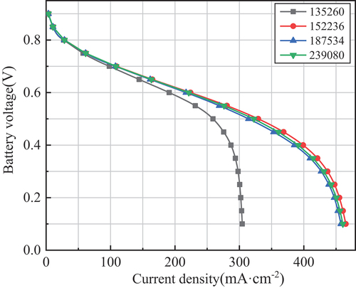
shows the polarization curves with eight branches, four ribs, and 45°Curvature when the number of grids is 135,260, 152,236, 187,534, and 239,080, respectively. The results show that the latter three meshing schemes are similar, whereas the first meshing scheme is relatively different from the three other schemes. In this study, the second scheme is selected as the mesh generation of the model, which can shorten the research time as much as possible to ensure accuracy.
Figure 3. Grid irrelevant.
Experiment validation
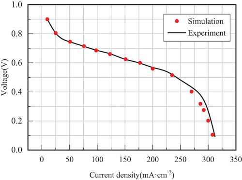
Um and Wang measured a set of polarization curve data of the straight FF through experiments (Sukkee and Yw Citation2003). Under the same size, boundary conditions, and operating conditions, this study established and simulated the same 3D geometric model of the straight FF. As shown in , the simulation results of the model are in good agreement with the experimental results, indicating that the numerical simulation process is reasonable and can be further extended to other FF structures.
Figure 4. Polarisation curves of straight FF simulation results and experimental data.
Results and discussion
Influence of the number of branches on the performance of the cathode radial FF
In this study, six PEMFC monomer models with different numbers of branches are established and simulated. Their corresponding numbers and structural characteristics are shown in .
Figure 5. Six PEMFC monomer models with different numbers of branches.
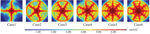
Oxygen distribution characteristics
shows the concentration distribution of oxygen in cathode GDL and Cl under 0.7 V working voltage. As shown in the figure, in this type of structure, the oxygen concentration is higher in each branch and its nearby area, whereas in the annular FF farther from the branch, it is significantly lower, undoubtedly causing the uneven oxygen distribution in the whole FF. Electrochemical reactions occurring on the CL are more intense in the region of high oxygen concentration, whereas that in the region with lower concentration are not fully carried out. The effect achieved by increasing the number of branches was investigated to solve this problem. The oxygen concentration in each layer of annular FFs improves as the number of branches increases, and the improvement is more evident in the inner layer, whereas the outer layer still has the problem of uneven oxygen distribution. In addition, the oxygen distribution performance of the symmetrical structure is better than that of the asymmetric structure. Cases 3 and 5, for example, showed more uniform oxygen distribution and better symmetry in the outer annular FFs, whereas Cases 4 and 6 showed significant oxygen concentration decay in the outer FFs (the most evident in the outermost FF).
Figure 6. Concentration distribution of oxygen at the cathode GDL and Cl interface of six schemes at 0.7 V working voltage.
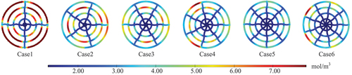
Water distribution characteristics
shows the concentration distribution of water on the cathode FF of six models under 0.7 V working voltage residual reaction gas, bringing the accumulated product water out of the FF. Thus, the distribution of oxygen and water in the FF has high contrast. The figure shows that the concentration of water is lower in branches and their adjacent area, which is due to the higher concentration of oxygen here, and sufficient oxygen can effectively produce a scavenging effect on the water. Similarly, increasing the number of branches can alleviate the problem of high water concentration in the FF. In schemes, such as Cases 3 and 5, the water is symmetrically distributed and the area of high water concentration within each annular FF is smaller, especially in Case 5, which has the best water removal performance among all schemes. By contrast, the distribution areas of high water concentrations within the asymmetrically distributed scheme show multiple and non-uniform characteristics.
Figure 7. Concentration distribution of product water in cathode FF under six schemes with a working voltage of 0.7 V.
Electrochemical properties
illustrates the electrochemical properties obtained by different schemes. As shown in , the voltage output of the fuel cell decreases with increasing current densities. At low current densities, the voltage difference between the six schemes is small. However, in the medium and high current density regions, the differences between schemes are gradually evident. As the number of branches increases, the voltage generated by the scheme with more branches under the same current density increases. However, the magnitude of this growth diminishes. For example, Case 5 has better output performance than Case 6. The same phenomenon appears in the power density curve ().
Figure 8. Polarization curves and power density curves obtained from different schemes.
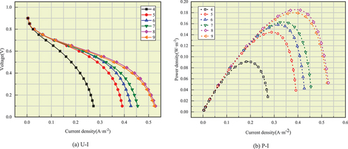
In the PEMFC, the increasing of rib area is conducive to the electron conduction. However, as the area of ribs increases, the width of the FF of each layer under the same FF area decreases, resulting in a decrease in the contact area between the FF and the GDL. This is detrimental for the diffusion of reaction gas in porous media. Therefore, the reasonable selection of the size of the FF and the rib plate is particularly important. As observed from polarization curves and current density curves, Case 5 is the best scheme in this study, in which the interaction between the rib area and FF area is the most effective for boosting the fuel cell output voltage and power.
Pressure drop in the cathode FF
The excessive pressure drop reduces the transmission efficiency of reaction gas in the channel. Thus, the pressure drop is an important index to evaluate the FF design. Therefore, the energy loss of PEMFC increases, resulting in its power reduction. shows that the pressure drop in the cathode FF gradually decreases as the number of branches increases, and the pressure drop corresponding to Case 5 is the smallest among the six schemes. Combining all results in this section, Case 5 with eight branches has the best improvement in fuel cell performance among all schemes, and other influencing factors are compared based on this number of branches in the subsequent study.
Figure 9. Pressure drop in cathode channel of six schemes.
Influence of the number of annular FF layers on the performance of the cathode radial FF
In this section, four options for the arrangement of FF layers are selected, as shown in .
Figure 10. Four options for the arrangement of FF layers.
Oxygen distribution characteristics
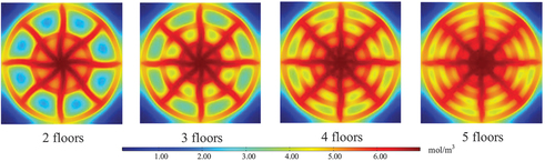
shows the concentration distribution of oxygen at the cathode GDL and CL interface of four schemes under the working voltage of 0.7 V. With the increase in the number of FF layers, the width of ribs between adjacent FFs is shortened. The effect of convective diffusion of gas under ribs is enhanced, and the concentration of oxygen under ribs is significantly increased. By contrast, the oxygen concentration in the annular FF does not improve significantly with the increase in FF layers. In the outer annular FF, the oxygen concentration in the area farther from the branches is still lower than that near branches.
Figure 11. At 0.7 V working voltage, the concentration distribution of oxygen at the cathode GDL and Cl interface of four schemes.
Water distribution characteristics
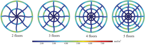
shows the concentration distribution of product water in the cathode FF under the voltage of 0.7 V. Different from the oxygen distribution, the water in the FF did not significantly improve when the number of FF layers increased. The water concentration in the FF of each layer at locations farther from branches is still higher than that in the area near the branches. The result shows that by increasing the number of FF layers, the oxygen concentration under the ribs is effectively improved.
Figure 12. Concentration distribution of product water in the cathode FF of four schemes when the working voltage is 0.7 V.
Electrochemical properties
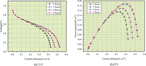
The polarization curves and power density curves obtained from four options () are compared. The result shows that the increase in the number of FF layers effectively improves the voltage and power output of the fuel cell at medium and high current densities. This finding is mainly because the increase in the number of channel layers expands the total area of the channel in the FF, which improves the effective area of gas diffusion to GDL through the channel, increases the effective area of electrochemical reaction on the membrane, and improves the output performance of the fuel cell. However, when the number of layers is continuously increased from the four-layer structure, the improvement brought by this change declines instead. At this time, the increasing FF areas further compress the total area of ribs, and the contact area between ribs and the MEA is continuously reduced, which is not conducive to the current conduction. The figure shows that in high current densities, the voltage and power output of the five-layer structure are rather inferior to that of the four-layer structure. In summary, among four options, the structure with four FF layers has the best interaction between the FF area and the rib area, in which the gas is most capable of participating in the reaction through the channel to the MEA whilst ensuring that the current can be adequately conducted.
Figure 13. Polarisation curve and power density curve of four schemes.
Pressure drop characteristic
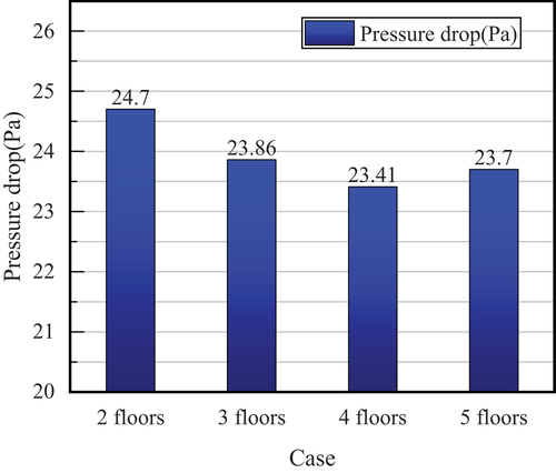
The comparison of the pressure drop characteristic shows that increasing the FF layers can reduce the pressure drop in the FF (). The pressure drop in the four-layer structure is the lowest among all four options.
Figure 14. Pressure drop of different options in the cathode FF.
Width between the annular FFs
The width between annular FFs (the width of ribs between FFs) was equal in all these options. To investigate whether this width affects the function of the fuel cell. In this subsection, we establish nine design scenarios with unequal width between adjacent FFs, as shown in , which can be broadly classified into three categories:
Figure 15. Nine design scenarios that employ unequal widths between adjacent FFs.
The width increases in steps from the inner layer to the outer layer, including scenarios A, B, and C;
The width is arranged symmetrically from the inner layer to the outer layer, which increases initially and then decreases, including scenarios D, E, and F;
The width is arranged at intervals from the inner layer to the outer layer, that is, for every other layer, the distance between the two adjacent FFs is the same, including scenarios G, H, and I.
The specific design scheme is shown in .
Table 5. Specific design scheme with different widths between adjacent FFs.
As shown in , the oxygen distribution at the interface between the cathode GDL and CL and the water distribution in the FF did not improve significantly with the increase in FF layers. The same characteristics appear in the current density, power density, and pressure drop produced by each structure. As shown in , the ultimate current density and maximum power density that can be achieved by all comparison schemes are lower than those of the isometric arrangement, and the voltage drop does not show a significant improvement.
Figure 16. Concentration distribution of oxygen at cathode GDL and Cl interface in 10 schemes.
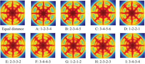
Figure 17. Concentration distribution of water in the cathode FF of 10 schemes.
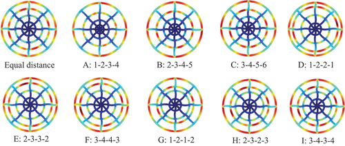
Figure 18. Ultimate current density and maximum power density.
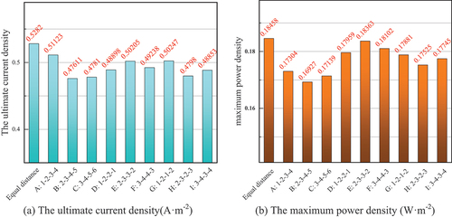
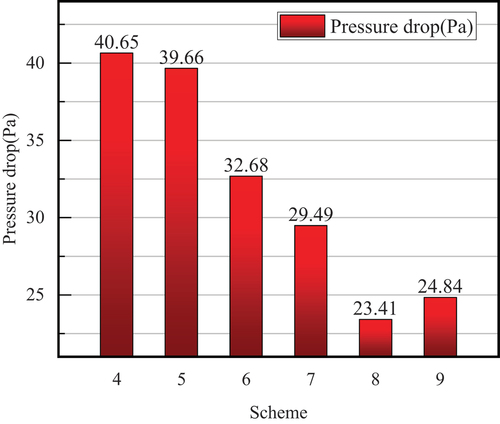
Figure 19. Pressure drop of ten schemes.
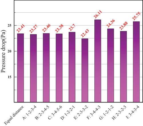
Based on this section, the isometric arrangement is still the optimal channel spacing setting mode for this type of radial FF, and this FF structure is also used in subsequent studies.
Influence of the amplitude of the waveform of branched FFs on the performance of the cathode radial FF
On the basis of optimization schemes in the previous sections, this section takes the amplitude of the waveform of branched FFs (α) as the research object. Three schemes (the amplitude of 15°, 30°, and 45°) are established (), and several types of performance of each scheme are compared as well.
Figure 20. Three schemes with the amplitude of 15°, 30°, and 45°.
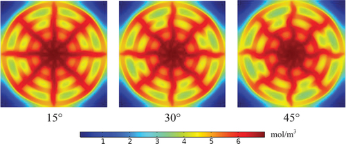
Oxygen distribution characteristic
As shown in , changing the amplitude does not evidently changes the oxygen distribution characteristic. In the outer annular FF, the problem of low oxygen content in some areas of the FF increases instead as the amplitude becomes larger. For example, in the 45° amplitude scheme, the region of low oxygen concentration in the outer annular FF is more pronounced than in the 15° amplitude scheme, which is certainly not conducive to the full occurrence of electrochemical reactions here.
Figure 21. Concentration distribution in oxygen FF of three schemes.
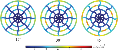
Water distribution characteristic
The increase in curvature adversely affects the oxygen distribution on the cathode side, which also affects the removal of water in the FF. As shown in , the negative effect of increasing the amplitude on the water in the FF is more severe than on oxygen. Greater amplitude indicates that the region of high water concentration appears more frequently in the annular FF, especially in the outer annular FF, and accordingly, the problem of water collection in the FF that impedes gas transport becomes more serious.
Figure 22. Concentration distribution in water cathode FF of three schemes.
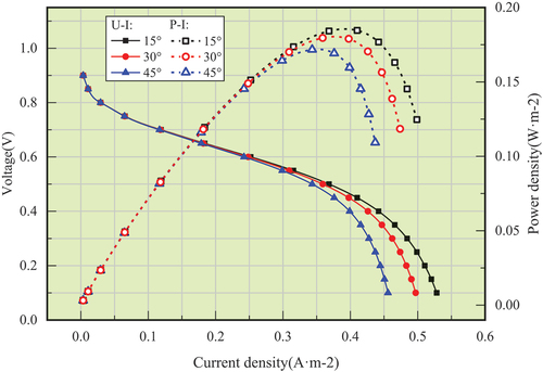
Electrochemical properties
The comparison of three schemes in the polarization and power density curves also confirms that increasing the amplitude is not conducive to the improvement of fuel cell performance (). At medium to high current densities, the smaller amplitude indicates electrochemical properties at the same current density.
Figure 23. Polarisation curves and power density curves obtained from different options.
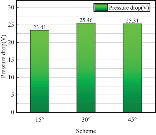
Pressure drop characteristic
The pressure drop characteristic also confirms the above inference (). The pressure drop increases accordingly by increasing the amplitude. By contrast, the lower amplitude indicates lower pressure drop and less pumping loss of the gas in the FF, resulting in a more adequate flow.
Figure 24. Pressure drop of different options in the cathode FF.
Conclusion
In this study, a new rim-type radial FF structure was designed by integrating the shape characteristics of the rim of a car tire with a radial FF on circular BPs.
The oxygen concentration in the annular FF of each layer improves with the increase in the number of branches. Increasing the number of branches, the voltage and power output of the fuel cell at medium to high current densities gradually increases, but the process does not last forever. In summary, the eight-branch scheme is the most appropriate.
With the increase in the number of layers, the width of the ribs between adjacent FFs was shortened, the effect of convective diffusion of gas under ribs was enhanced and the concentration of oxygen under ribs was significantly increased. However, when the number of layers is continuously increased from the four-layer structure, the improvement brought by this change declines instead. In summary, for the selection of the number of FF layers, this study concluded that a four-layer structure is the most appropriate.
The oxygen distribution at the interface between the cathode GDL and CL and the water distribution in the FF did not improve evidently with the change in the width of the adjacent FFs.
In the outer annular FF, the problem of low oxygen content in some areas of the FF increases instead as the curvature becomes larger. In summary, for the selection of the curvature of the branch, this study concluded that 15° is the most appropriate.
Disclosure statement
No potential conflict of interest was reported by the authors.
Additional information
Funding
References
- Asadzade, M., and A. Shamloo. 2017. Design and simulation of a novel bipolar plate based on lung-shaped bio-inspired flow pattern for PEM fuel cell. International Journal of Energy Research 41 (12):1730–39. doi:10.1002/er.3741.
- Atyabi, S. A., and E. Afshari. 2019. A numerical multiphase CFD simulation for PEMFC with parallel sinusoidal flow fields. Journal of Thermal Analysis and Calorimetry 135 (3):1823–33. doi:10.1007/s10973-018-7270-3.
- Berna, S., G.C. Dilara, D. Yilser, S. Thomas, and E. Inci. 2016. Modeling and sensitivity analysis of high temperature PEM fuel cells by using COMSOL multiphysics. International Journal of Hydrogen Energy 41(23): 10001–10009. ISSN:.
- Dang, D. K., and B. Zhou. 2022. Investigation of liquid water behaviors inside a PEMFC cathode with a leaf-like biomimetic flow field design based on Murray’s Law. International Journal of Green Energy 19 (6):577–91. doi:10.1080/15435075.2021.1951739.
- Frappé, E., A. De Bernardinis, O. Bethoux, D. Candusso, F. Harel, C. Marchand, et al. 2011. PEM fuel cell fault detection and identification using diflow fielderential method: Simulation and experimental validation. The European Physical Journal Applied Physics 54(2). doi:10.1051/epjap/2011100277.
- Ghadhban, S. A., W. H. Alawee, and H. A. Dhahad. 2021.Study eflow fieldects of bio-inspired flow filed design on polymer electrolyte membrane fuel cell performance. Case Studies in Thermal Engineering 24: 100841.doi: 10.1016/j.csite.2021.100841
- He, K., C. Zhang, Q. He, Q. Wu, L. Jackson, and L. Mao. 2020. Eflow fieldectiveness of PEMFC historical state and operating mode in PEMFC prognosis. International Journal of Hydrogen Energy 45 (56):32355–66. doi:10.1016/j.ijhydene.2020.08.149.
- Jia, Y., B. Sunden, and G. Xie. 2019. A parametric comparison of temperature uniformity and energy performance of a PEMFC having serpentine wavy channels. International Journal of Energy Research 43 (7):2722–36. doi:10.1002/er.4327.
- Laribi, S., K. Mammar, Y. Sahli, A. Necaibia, F. Z. Arama, and T. Ghaitaoui. 2021.PEMFC water diagnosis using PWM functionality signal and fractional order model. Energy Reports 7: 4214–21.doi: 10.1016/j.egyr.2021.07.010
- Lian, Y., X. Qz, and Z. Mg. 2020. Investigation on the optimal angle of a flow-field design based on the leaf-vein structure for PEMFC. International Information and Engineering Technology Association 23 (4):262–68.
- Marappan, M., R. Narayanan, K. Manoharan, M. K. Vijayakrishnan, K. Palaniswamy, S. Karazhanov, and S. Sundaram. 2021. Scaling up Studies on PEMFC using a modified serpentine flow field incorporating porous sponge inserts to observe water molecules. Molecules 26 (2):286. doi:10.3390/molecules26020286.
- Niu, Z., L. Fan, Z. Bao, and K. Jiao. 2018. Numerical investigation of innovative 3D cathode flow field in PEMFC. International Journal of Energy Research 42 (10):3328–38. doi:10.1002/er.4086.
- Perez-Raya, I. P. I., et al. New radial-based flow configurations for PEMFCs. In Rubio-Arana, J. C. eds. ASME International Mechanical Engineering Congress and Exposition, 2010. Lake Buena Vista, FL:AMER SOC MECHANICAL ENGINEERS, p. 673–681.
- Ramiar, A., A.H. Mahmoudi, Q. Esmaili, and M. Abdollahzadeh. 2016. Influence of cathode flow pulsation on performance of PEMFC with interdigitated gas distributors. Energy 94:206–217.
- Sadeghifar, H., A. Torkavannejad, and N. Pourmahmoud. 2018.A novel, net-shape polymer electrolyte fuel cell: Higher power density, smaller stack size and less bipolar plate required. International Journal of Heat and Mass Transfer 117: 1099–106.doi: 10.1016/j.ijheatmasstransfer.2017.10.078
- Selem, S. I., H. M. Hasanien, and A. A. El Fergany. 2020. Parameters extraction of PEMFC’s model using manta rays foraging optimizer. International Journal of Energy Research 44 (6):4629–40. doi:10.1002/er.5244.
- Sezgin, B., D. G. Caglayan, Y. Devrim, T. Steenberg, and I. Eroglu. 2016. Modeling and sensitivity analysis of high temperature PEM fuel cells by using COMSOL multiphysics. International Journal of Hydrogen Energy 41 (23):10001–09. doi:10.1016/j.ijhydene.2016.03.142.
- Solati, A., B. Nasiri, A. Mohammadi-Ahmar, K. Mohammadi, and A. H. Safari. 2019.Numerical investigation of the eflow fieldect of diflow fielderent layers configurations on the performance of radial PEM fuel cells. Renewable Energy 143: 1877–89.doi: 10.1016/j.renene.2019.06.003
- Sukkee, U., and C. Yw. 2003. Three-Dimensional analysis of transport and electrochemical reactions in polymer electrolyte fuel cells. Journal of Power Sources 125:40–51.
- Timurkutluk, B., and M. Z. Chowdhury. 2018. Numerical investigation of convergent and divergent parallel flow fields for PEMFCs. Fuel Cells 18 (4):441–48. doi:10.1002/fuce.201800029.
- Xie, Q. 2021. CFD simulation and investigation of a new radial flow field structure on the PEMFC circular bipolar plate. International Journal of Electrochemical Science. ArticleID:211057. doi: 10.20964/2021.10.48.
- Xie, Q., and M. Zheng. 2021. CFD simulation and performance investigation on a novel bionic spider-web-type flow field for PEM fuel cells. Processes 9 (9):1526. doi:10.3390/pr9091526.
- Xiong, C., M. Luo, B. Chen, and Z. Tu. 2018. Eflow fieldect of channel structure on oxygen distribution in cathode of fuel cells. Power Source Technology 42:230–32.
- Xu, Y., L. Peng, P. Yi, and X. Lai. 2019. Numerical investigation of liquid water dynamics in wave-like gas channels of PEMFCs. International Journal of Energy Research 43 (3):1191–202. doi:10.1002/er.4353.
- Yutao, L., and Z. Minggang. 2021. Performance investigation on the radial flow field of PEMFC. International Journal of Ambient Energy 1–8. doi:10.1080/01430750.2021.1914161.
- Yu-Ting, L., L. Gui, and L. Yuan-Yuan. 2020. Performance optimization of PEMFC with snow-flake topological plate. Journal of Engineering Thermophysics 41 (12):2900–07.
- Zhang, S., H. Xu, Z. Qu, S. Liu, and F. K. Talkhoncheh. 2022.Bio-Inspired flow field designs for PEMFCs: A review. Journal of Power Sources 522: 231003.doi: 10.1016/j.jpowsour.2022.231003
- Zhu, W., and M. Zheng. 2019. Radial flow field of circular bipolar plate for PEMFCs. International Journal of Heat and Technology 37 (3):733–40. doi:10.18280/ijht.370309.