
ABSTRACT
Hierarchical surfaces comprised both microscale and nanoscale structures have been previously studied as a means of targeting multiple length scales to achieve superior pool boiling performance. However, preceding studies have focused almost exclusively on high surface tension working fluids, while technologically important low surface tension fluids have remained largely unexplored. Due to their significantly lower surface tension these liquids tend to push out the air trapped in surface cavities of the heating surface, resulting in fewer nucleation sites compared to the same surface in water at low to moderate superheats. Thus, developing effective surface modification techniques for pool boiling in dielectric liquids and understanding the multiphase physics behind them is a pressing need in order to overcome these performance limitations and accelerate their adoption. In this work, we utilize scalable manufacturing techniques to realize four separate surface types (planar, nanoscale-modified, microscale-modified, and hierarchical) and experimentally determine their respective pool boiling performance within the low surface tension commercial working fluid HFE-7100. A maximum heat transfer enhancement of 125% at 38 K of superheat was observed for the best performing samples, which interestingly were nanoscale-modified and not those of the hierarchical type. Visual observations via high-speed video analysis of vapor bubble behavior are utilized to explain the underlying multiphase physics as to why these samples performed so well and future directions for achieving surface optimization across multiple length scales.
Introduction
Pool boiling as a passive heat transfer technique has the ability to remove significantly larger amounts of heat compared to single-phase natural or forced convection mechanisms. With the ever-increasing power dissipation densities associated with modern electronics, direct immersion pool boiling within dielectric fluids is now gaining traction as a viable thermal management strategy for electronics hardware and data centers [Citation1]. Engineered heat transfer dielectric fluids such as FluorinertTM (FC-72, FC-770, FC-87, and others) have been widely used for direct contact/immersion cooling. Due to concern about their high global warming potential, they are now being replaced by NovecTM fluids such as HFE-7000, HFE-7100, and HFE-7300. In addition to their dielectric nature, the lower saturation point (e.g. 61°C at atmospheric pressure for HFE-7100) compared to water makes these fluids compatible with direct contact phase change thermal management approaches for electronics [Citation2]. However, other important thermal properties of these working fluids such as specific heat and thermal conductivity are inferior to water, ethanol, and many other non-dielectric liquids. In addition, due to their significantly lower surface tension these liquids tend to push out the air trapped in surface cavities of the heating surface. As a result, fewer nucleation sites are active for a surface immersed in a dielectric liquid than compared to the same surface in water at low to moderate superheats [Citation3, Citation4]. Thus, developing effective surface modification techniques for pool boiling in dielectric liquids and understanding the multiphase physics behind them is a pressing need in order to overcome these performance limitations and accelerate their adoption [Citation4].
Advances in chemistry, surface science, and microfabrication have facilitated the formation of a variety of micro- and nanoscale features for enhancing pool boiling heat transfer including coatings [Citation5], nanowires [Citation6], foams [Citation7, Citation8], pins/fins [Citation9, Citation10], open channels [Citation11, Citation12], grooves [Citation13] and as well as nanofluids [Citation14, Citation15]. Comprehensive reviews of surface modification for pool boiling enhancement can be found elsewhere [Citation16–18]. These features improve boiling performance by a combination of means, including increasing the wetted surface area, altering the movement or behavior of phase interfaces, facilitating faster surface rewetting, and increasing the number of active nucleation sites. In some studies, periodically ordered microscale features with nanostructure-modified surfaces were used to create a hierarchical surface [Citation19–23] in order to target multiple length scales and promote additional heat transfer enhancement. However, almost all existing hierarchical surface studies have been conducted with water as the working liquid. The significant differences in thermophysical properties influence critical pool boiling parameters such as capillary length (2.7 mm for water compared to 0.9 mm for HFE-7100 [Citation24]), nucleation site activity, and bubble departing diameter such that generalizing the benefits of a given hierarchical surface across working fluid types is not trivial. Thus, there is a pressing knowledge gap regarding what makes for an effective hierarchical surface modification strategy for highly wetting dielectric working fluids in pool boiling environments.
In this work, a series of pool boiling experiments were conducting in the commercial dielectric fluid HFE-7100 on planar baseline, microstructure-modified, nanostructure-modified, and hierarchical (microstructures + nanostructures) surfaces. For all samples, copper was the starting sample material. Low profile copper 1D micro-fin arrays (MFAs) were fabricated using a high throughput roll molding method. Copper oxide nanostructures (CuO NS) were formed on the exposed copper surfaces through a low-cost and industry-compatible chemical oxidation technique. In this way, four different sample types (planar Cu, planar Cu + CuO NS, Cu MFA, and hierarchical Cu MFA + CuO NS) were tested within the same pool boiling environment and their respective heat transfer performances determined. In addition, important vapor bubble parameters such as bubble density and departing diameter associated with each sample type for various heat fluxes were quantified by image processing of high-speed video.
Materials and methods
The planar copper surfaces were cleaned with solvents to remove surface contaminants but otherwise were tested as-received. The 1D MFAs were created using an established high throughput roll molding method as described in Ref [Citation25]. For this work specifically, Cu strips were mechanically polished and then annealed at 600°C for 12 h. A normal force of 133.4 kN was exerted during the roll molding of copper to create MFA with a trapezoidal cross section of ~400 µm height. The resulting pitch was 973 µm and the micro-fin width at top was 595 µm. After roll molding, samples were cut into to squares of 25.4 mm edge length and consisted of 26 micro-fins per sample.
To create samples with nanostructured surfaces, Cu planar or Cu MFA samples were oxidized in an aqueous ammonia solution to grow copper (ΙΙ) oxide (CuO) NS on the exposed surfaces. To first remove native oxide, the samples were immersed in a 3.0 M hydrochloric acid bath for at least 40 s. After rinsing the samples in deionized (DI) water and drying, they were submerged in a 0.15 M ammonia solution which was pre-heated to 60°C in a container with a ventilation lid. The reacted solution was exchanged with fresh solution of the same composition two times at approximately 8-h intervals during the process. The oxidation process took 18 h for a 25.4 mm × 25.4 mm planar copper sample, while for the rolled samples of the same footprint full coverage with the CuO NS was observed to take almost twice as long. The representative images of planar Cu, planar Cu + CuO NS, Cu MFA, and hierarchical Cu MFA + CuO NS samples are given in .
Figure 1. (a) Left to right: as-received copper square with native oxide, sample after sanding and HCl treatment, and sample after oxidation to form CuO NS. (b) SEM image of as-rolled Cu MFA sample. (c-e) SEM images at increasing magnification of a Cu MFA with CuO NS present on its surfaces. (f) EDAX analysis of an oxidized sample indicating Cu, O, and trace amounts of Si and C. (g) 3D laser scanning confocal topology mapping of rolled Cu MFA sample. (h) Static contact angle measurements using DI water on planar copper sample pre-oxidation and (i) post-oxidation.
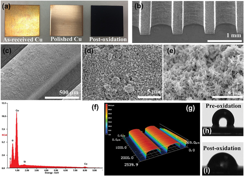
An analysis of the elemental composition of the black film formed via oxidation was performed using energy dispersive spectroscopy (EDS) () and indicated that the black surface film was composed almost entirely of Cu and O with negligible detection of contaminants C and Si, which may originate from the sample chamber or sample preparation. A representative 3D laser scanning confocal topology of a rolled sample is shown in . Via laser topology measurements, the average surface roughness of the as-received planar samples, rolled MFA samples, and hierarchical samples were found to be 0.6 µm, 6.8 µm, and 13.8 µm, respectively. Thus, both the roll molding and oxidation processes increase surface roughness above that of the as-received planar samples.
Static contact angle measurements were carried out via drop shape analyzer with DI water as the fluid. The inherently low surface tension of HFE-7100 made accurate measurement of the low (<5°) contact angles difficult, hence relative wettability comparisons were performed using DI water instead. Results showed that the oxidized Cu surfaces possessed greater wettability as compared to the unoxidized Cu as can be seen in ), with a contact angle of 108° observed for control planar samples versus 84° for the planar CuO NS samples.
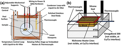
A schematic of the pool boiling experiment setup is shown in and described in detail in our previous publication [Citation26]. In brief, the experimental rig included a sample stage enclosed in a pool boiling tank. The sample stage consisted of a PTFE base, a second PTFE frame enclosing the sample circumference, a copper heat spreader block, and the sample under test. A compact serpentine Nichrome heater was adhered to the backside of the sample and above the copper heat spreader block using a thermally conductive epoxy (OMEGABONDTM 200) to minimize the thermal resistance between the heater and the sample. All seams on the sample stage were sealed with high-temperature RTV silicone. Two K-type thermocouples (Omega) were inserted in shallow trenches machined on the back surface of the sample block and kept in place with the thermally conductive epoxy such that the resistance of the epoxy would not lie in series between the junction and the copper. The boiling tank was equipped with transparent windows for high-speed imaging. The working fluid used in this study was NovecTM HFE-7100 fluid from 3 MTM, a low surface tension dielectric liquid with saturation temperature of 61°C at atmospheric pressure. During the experiment, the tank was filled three-quarters full with HFE-7100 fluid while the position of the sample stage was adjusted in front of the viewport using mechanical supports. The HFE-7100 was degassed through repeating heating cycles before being used in the final experiment. Two liquid-to-air reflux heat exchanger loops were used in the tank; one served as the condenser positioned above the pool for maintaining the liquid level during the boiling, and second one at the bottom of the tank (to minimize the natural convection currents) for maintaining the pool temperature. The pool temperature of the tank was recorded using a submerged K-type thermocouple. Throughout the boiling, the pressure was maintained at 1 atm by an automated pressure control valve. The automated boiling experiment started with applying a voltage via computer-controlled DC power supply while recording the temperature, evaluating the steady-state condition via predefined closed-loop control algorithm, and incrementing the voltage once steady-state at a given power level was reached. Further details about the automated performance testing and data processing are outlined in our previous publication [Citation26]. Three separate samples of each surface type were tested independently, and the results showed repeatability within experimental uncertainty over multiple runs over the same sample. All heat flux values were defined using the projected base area of 25.4 mm × 25.4 mm.
Figure 2. (a) Schematic of the pool boiling tank setup used for sample evaluation (b) detailed schematic of the sample stage.
Visualization of the phase change bubble behavior over the heating surfaces and under different heating conditions was performed using a high-speed camera (Phantom VEO 410, Vision Research) equipped with a manual zoom lens (Resolv4KⓇ, NavitarⓇ) to maintain a high-resolution zoom. All the high-speed videos were recorded at steady-state thermal condition. The high-speed videos were recorded at frame rates between 1000 and 4000 depending on the frame size (full-frame or zoom). Automated image-processing scripts were written in MATLAB for counting the bubbles and measuring the bubble departing diameters. The algorithm includes reducing the noise, separating the in-focus bubbles from the background, edge detection/binarization for finding the bubble outline, morphological operations for clean up the circular objects, and Circular Hough Transform operation for detecting and quantifying the bubbles.
Results
The boiling curves of planar copper with and without CuO NS are plotted in . As can be seen, the performance of the two groups was almost identical within the natural convection regime with negative superheats. It may be expected that the CuO NS samples would exhibit superior heat transfer due to their significantly larger amount of surface area. However, it has been experimentally shown that nanoscale surface area enhancements alone do not directly lead to enhancements in pool boiling performance and that other surface factors such as wickability, nucleation site activity, and influence from microscale bubble dynamics play a greater role [Citation26]. At low superheats before bubble nucleation has begun, none of these factors were at play and the heat transfer was thus comparable between the two surface types. At greater superheats where nucleate boiling is occurring, however, the planar CuO NS samples did exhibit a markedly superior heat transfer performance than the unmodified planar Cu samples. We attribute this to an improved ability of the CuO NS samples to wick liquid back to the surface after a vapor bubble departs as compared to the planar Cu surface, thus providing more efficient rewetting action and increased heat transfer rates. This is also supported by the contact angle measurements presented in .
Figure 3. (a) Pool boiling performance curves of planar samples before and after growing CuO NS (b) pool boiling performance curves of planar Cu, rolled Cu MFA, and MFA + CuO NS hierarchical samples.
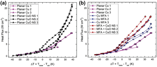
We next consider the performance of the roll-molded MFA samples, both as-rolled and with CuO NS grown onto the Cu MFA surfaces after roll molding. From the heat transfer performance of all MFA samples was better than the planar Cu surface within the natural convection regime, especially above −10 K superheat due to having greater surface area. The pool boiling results for the Cu MFAs were comparable to those observed in our previous work on aluminum alloy MFAs of similar micro-fin height, pitch, and spacing [Citation12]. In both studies, in the natural convection regime, when the superheat (ΔT = Tbase – Tsat) was below 10 K, the heat transfer performance across all MFA structured surface samples was similar. Distinct performance differences among MFA sample types only became noticeable when ΔT exceeded 10 K. Beyond this point, nucleate boiling was evidently starting.
A modest but measurable additional improvement in the boiling performance was achieved over all superheats for the hierarchical Cu MFA + CuO NS samples. However, by comparing the results in with those in , it can be seen that the performance of the hierarchical Cu MFA + CuO NS samples was not superior to the performance of the planar CuO NS samples. Indeed, out of all the sample types tested the planar CuO NS samples demonstrated the best overall heat transfer performance.
These findings regarding the efficacy of hierarchical surface modifications for enhancing boiling heat transfer are in agreement with the water-centric work of Cho et al. [Citation27]. They reported that surfaces with smaller micro/nanostructures with strong wickability can have a higher heat transfer coefficient (HTC) compared to large microstructures with strong wickability. In contrast, surfaces with large microstructures but weaker wickability in general showed the smallest HTC. It is important that in this work we observe that a similar relationship exists even for the lower surface tension liquid HFE-7100.
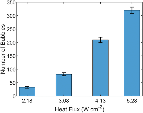
To further understand the bubble dynamics associated with each sample type, high-speed video from the experiments was analyzed. shows high-speed images of the nucleate boiling over the hierarchical copper surface at four levels of heat flux. This figure reveals that the majority of the bubbles are located on top of the MFAs. This is in agreement with the findings of our previous work regarding the nucleation pool boiling over aluminum MFAs and confirms the capability of MFAs, with or without NS, in controlling the nucleation on the heating surface by separating the vapor and liquid paths in subcooled dielectric liquids [Citation12]. In both studies, the high-speed videos demonstrated that the distinct regions of single-phase flow moving upward and downward, which start at low levels of superheat, significantly affect the initiation of bubble nucleation. When the superheat is moderate, it is clear that vapor bubbles start to form first on the bottom of the surfaces, confirming that these are likely the hottest parts of the MFA. Yet, according to the high-speed video recordings, these bubbles move quickly to the top of the micro-fins immediately after they appear. Image processing of approximately 25,000 frames showed a linear trend in the number of counted bubbles for heat fluxes above 2.18 W/cm2, as shown in .
Figure 4. Bubble distribution at heat fluxes of (a) 2.18, (b) 3.08, (c) 4.13, and (d) 5.28 W/cm2 over hierarchical Cu MFA + CuO NS samples. The images are captured from 3000 fps video with a 330 µs exposure time.
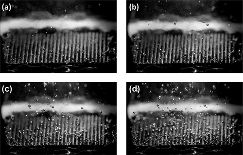
Figure 5. Average number of counted bubbles as a function of heat flux. Representative frames of each heat flux are shown in .
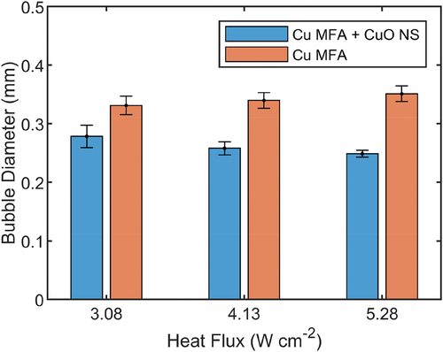
Detailed views of the bubble activity over the MFAs are shown in where two nucleation sites on micro-fin tops are emphasized for discussion. The composite image provides the ebullition cycle to be about 250 ms for the two different nucleation sites marked with yellow and orange color. At this power level, most of the bubbles slide freely over the fin top and coalesce with other bubbles located over the same fin, while a few roll over the channels, coalesce with the bubbles of the neighbor micro-fins, or even slide across the micro-fins. At higher heat fluxes (above 4.13 W/cm2), most of the bubble departure events occur directly after coalescence due to large density of the bubbles whereas at lower heat fluxes, the bubbles rest longer over the fin, expand, and depart due to buoyancy. Automated image-processing of the frames captured in the high-speed video calculates the average departing diameter of 327 µm for the MFA samples and 268 µm for the oxidized MFA + CuO NS rolled samples over the recorded heat fluxes. The increase in the heat fluxes results in slightly larger departing diameter with less than 10% variation across the studied heat fluxes. Details of the bubble measurements statistics are shown in .
Figure 6. Bubble ebullition cycle and the nucleation sites illustrated in composite images. The dashed yellow and orange circles show two nucleation sites with periods of approximately 0.25 s. Images are from a high-speed video of an oxidized rolled sample at q = 3.08 W/cm2 recorded at 2000 fps and selected at 50 ms intervals.
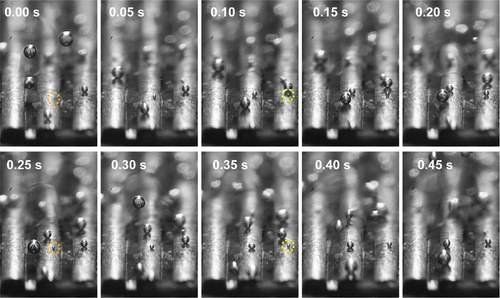
Figure 7. Measured departing bubble diameter at various heat fluxes for MFA samples.
Discussion
Despite the similarity of our findings with those of Cook et al. [Citation11] regarding the benefits of MFA surface structuring, in our study nucleation sites were mostly observed on micro-fin tops, while fewer were located on micro-fin side walls and a very small fraction occurred inside the channel. This difference indicates that the specific design of the MFA surface can significantly influence where bubbles form, which in turn can impact the effectiveness of heat transfer. Cook et al. [Citation11] used MFA structures fabricated by a CNC machine with cutting tools known as end mills, whereas in this study it is created on copper strips using a roll molding method, and the geometry is trapezoidal.
Moreover, the bubble growth mechanism was different than the mechanism described by Walnuj et al. [Citation28] in which nucleation occurred at the channel corner and bubbles grew in a vertical direction along the channel wall. In our case, bubbles did not primarily nucleate at the corner of the channels, and were free to slide horizontally and coalesce. This was attributed to smaller ratio of departing bubble diameter to channel width in our MFAs, as well as the MFA-induced periodic flow patterns discussed in our previous work [Citation26].
These visual observations regarding bubble nucleation location and subsequent behavior also help to explain why the planar CuO NS samples outperformed the hierarchical MFA + CuO NS samples. For both types of planar samples, regions of upward flow of heated fluid from the surface and downward flow of cooler fluid from the pool were not laterally constrained in terms of interactions with the planar sample surface. Regions were free to form according to the local temperature distribution and as critical flow pattern-defining forces dictate. The superior wetting of the CuO NS samples compared to the Cu samples significantly enhanced the rate of heat transfer via faster quenching of the surface upon vapor bubble departure, and the subsequent flow patterns were similarly not laterally constrained along the sample surface.
For MFA-modified surfaces, there was an obvious increase in surface area that did indeed result in improved heat transfer performance compared to the baseline planar Cu samples. However, the fluid flow patterns were strongly influenced by the presence of the micro-fins and their associated micro-channels such that the degree of lateral flow freedom was reduced compared to planar samples. A more detailed discussion of MFA-induced periodic flow patterns may be found in our previous work on unmodified aluminum MFAs [Citation26]. Briefly, within the lower superheat natural convection regime, due to the difference in material thickness the bottom of the micro-channel regions will have a higher temperature than the tops of the micro-fins. We conservatively estimate this difference to be small but not insignificant, on the order of ~0.5 K for Cu based on a simple thermal resistance model. This creates a net upward fluid flow from the hotter micro-channel bottoms and along micro-fin sidewalls which wraps around the top corners due to boundary layer adhesion, as well as an associated downward replenishing flow of cooler fluid from the far-field pool environment directed toward the center of the micro-channels. These periodic, alternating regions of flow have a strong influence on subsequent bubble nucleation location preference and even vapor bubble migration to micro-fin tops from within the micro-channels. When the Cu MFAs are modified to be hierarchical with the addition of CuO NS, they also benefit from the superior wetting and overall heat transfer is enhanced relative to the Cu MFA samples. Further, as shown in the departure diameter for these CuO NS-modified hierarchical samples is measurably smaller than for the Cu MFA samples, which suggests a reduction in adhesion force that promotes bubble departure.
However, the quantitative degree to which these enhancements are effective was observed to be relatively modest compared to the large enhancement from planar Cu vs planar CuO NS. In addition, the planar CuO NS samples outperformed the hierarchical sample despite the greater surface area of the latter. These results indicate that the critical fluid flow length scales and region of influence associated with the high wicking action of the CuO NS must be greater than the spatial period of the MFAs such that the presence of the micro-fins and their associated flow patterns actually disrupt or limit the lateral length scales that would otherwise occur as for the planar samples. This is an important finding, as it is not inherently obvious that the beneficial increase in surface area from the microscale features needs to be balanced with their influence of potentially millimeter-scale flow patterns which become stronger when highly wetting nanostructures are present. From a design perspective, this indicates that there should exist an optimal microscale feature spacing at which lateral flow is not strongly constrained but a significant surface area enhancement is still possible and that this optimal condition will be dependent on the strength of a given nanostructured surface’s wettability. Future scientific investigations are required to explore this dichotomy further and provide sufficient data and understanding to enable true hierarchical surface design and optimization a priori rather than via trial and error.
Acknowledgments
The authors gratefully acknowledge support from the National Science Foundation through cooperative agreement OIA-1541079 and the Louisiana Board of Regents. This material is also based upon work supported by the National Science Foundation under Grant Number 1846165.
Disclosure statement
No potential conflict of interest was reported by the author(s).
Additional information
Funding
References
- K. C. Leong, J. Y. Ho, and K. K. Wong, “A critical review of pool and flow boiling heat transfer of dielectric fluids on enhanced surfaces,” Appl. Therm. Eng., vol. 112, pp. 999–1019, 2017. DOI: 10.1016/j.applthermaleng.2016.10.138.
- A. Moita, E. Teodori, and A. Moreira, “Influence of surface topography in the boiling mechanisms,” Int. J. Heat Fluid Flow, vol. 52, pp. 50–63, 2015. DOI: 10.1016/j.ijheatfluidflow.2014.11.003.
- M. S. El-Genk and H. Bostanci, “Saturation boiling of HFE-7100 from a copper surface, simulating a microelectronic chip,” Int. J. Heat Mass Tran., vol. 46, no. 10, pp.1841–1854, 2003. DOI: 10.1016/S0017-9310(02)00489-1.
- J. L. Parker, Pool Boiling of Dielectric Liquids on Porous Graphite and Extended Copper Surfaces. The University of New Mexico, 2008.
- A. R. Betz, J. Jenkins, and D. Attinger, “Boiling heat transfer on superhydrophilic, superhydrophobic, and superbiphilic surfaces,” Int. J. Heat Mass Tran., vol. 57, no. 2, pp.733–741, 2013. DOI: 10.1016/j.ijheatmasstransfer.2012.10.080.
- Z. Yao, Y.-W. Lu, and S. G. Kandlikar, “Fabrication of nanowires on orthogonal surfaces of microchannels and their effect on pool boiling,” J. Micromech. Microeng., vol. 22, no. 11, pp.115005, 2012. DOI: 10.1088/0960-1317/22/11/115005.
- L. L. Manetti, A. S. O. H. Moita, R. R. de Souza, and E. M. Cardoso, “Effect of copper foam thickness on pool boiling heat transfer of HFE-7100,” Int. J. Heat Mass Tran., vol. 152, pp. 119547, 2020. DOI: 10.1016/j.ijheatmasstransfer.2020.119547.
- K. Pratik, A. Nammari, T. S. Ashton, and A. L. Moore, “Saturated pool boiling heat transfer from vertically oriented silicon surfaces modified with foam-like hexagonal boron nitride nanomaterials,” Int. J. Heat Mass Tran., vol. 95, pp. 964–971, 2016. DOI: 10.1016/j.ijheatmasstransfer.2016.01.006.
- K.-H. Chu, R. Enright, and E. N. Wang, “Structured surfaces for enhanced pool boiling heat transfer,” Appl. Phys. Lett., vol. 100, no. 24, pp.241603, 2012. DOI: 10.1063/1.4724190.
- S. H. Kim, et al. “Boiling heat transfer and critical heat flux evaluation of the pool boiling on micro structured surface.” Int. J. Heat Mass Tran., vol. 91, pp. 1140–1147, 2015. DOI: 10.1016/j.ijheatmasstransfer.2015.07.120.
- D. Cooke and S. G. Kandlikar, “Effect of open microchannel geometry on pool boiling enhancement,” Int. J. Heat Mass Tran., vol. 55, no. 4, pp.1004–1013, 2012. DOI: 10.1016/j.ijheatmasstransfer.2011.10.010.
- B. Doran, et al. “Spatially periodic vapor bubble activity during subcooled pool boiling on 1D aluminum alloy micro-fin arrays.” Int. J. Heat Mass Tran., vol. 180, pp. 121760, 2021. DOI: 10.1016/j.ijheatmasstransfer.2021.121760.
- A. Das, P. Das, and P. Saha, “Performance of different structured surfaces in nucleate pool boiling,” Appl. Therm. Eng., vol. 29, no. 17–18, pp.3643–3653, 2009. DOI: 10.1016/j.applthermaleng.2009.06.020.
- M. Roodbari, H. Alimoradi, M. Shams, and C. Aghanajafi, “An experimental investigation of microstructure surface roughness on pool boiling characteristics of TiO2 nanofluid,” J. Therm. Anal. Calorim., vol. 147, no. 4, pp.3283–3298, 2022. DOI: 10.1007/s10973-021-10666-w.
- H. Seon Ahn and M. Hwan Kim, “A review on critical heat flux enhancement with nanofluids and surface modification.” J Heat Transfer, vol. 134, no. 2, 2012. DOI: 10.1115/1.4005065.
- G. Liang and I. Mudawar, “Review of pool boiling enhancement by surface modification,” Int. J. Heat Mass Tran., vol. 128, pp. 892–933, 2019. DOI: 10.1016/j.ijheatmasstransfer.2018.09.026.
- A. Mehralizadeh, S. R. Shabanian, and G. Bakeri, “Effect of modified surfaces on bubble dynamics and pool boiling heat transfer enhancement: a review,” Thermal. Sci. Eng. Prog., vol. 15, pp. 100451, 2020. DOI: 10.1016/j.tsep.2019.100451.
- U. Sajjad, A. Sadeghianjahromi, H. M. Ali, and C.-C. Wang, “Enhanced pool boiling of dielectric and highly wetting liquids-a review on enhancement mechanisms,” Int. Commun. Heat Mass Transf, vol. 119, pp. 104950, 2020. DOI: 10.1016/j.icheatmasstransfer.2020.104950.
- Z. Cao, et al. “Pool boiling heat transfer of FC-72 on pin-fin silicon surfaces with nanoparticle deposition.” Int. J. Heat Mass Tran., vol. 126, pp. 1019–1033, 2018. DOI: 10.1016/j.ijheatmasstransfer.2018.05.033.
- K.-H. Chu, Y. Soo Joung, R. Enright, C. R. Buie, and E. N. Wang, “Hierarchically structured surfaces for boiling critical heat flux enhancement,” Appl. Phys. Lett., vol. 102, no. 15, pp.151602, 2013. DOI: 10.1063/1.4801811.
- A. M. Gheitaghy, H. Saffari, and M. Mohebbi, “Investigation pool boiling heat transfer in U-shaped mesochannel with electrodeposited porous coating,” Exp. Therm. Fluid Sci., vol. 76, pp. 87–97, 2016. DOI: 10.1016/j.expthermflusci.2016.03.011.
- A. Jaikumar and S. G. Kandlikar, “Enhanced pool boiling heat transfer mechanisms for selectively sintered open microchannels,” Int. J. Heat Mass Tran., vol. 88, pp. 652–661, 2015. DOI: 10.1016/j.ijheatmasstransfer.2015.04.100.
- M. M. Rahman, E. Olceroglu, and M. McCarthy, “Role of wickability on the critical heat flux of structured superhydrophilic surfaces,” Langmuir, vol. 30, no. 37, pp.11225–11234, 2014. DOI: 10.1021/la5030923.
- M. Misale, G. Guglielmini, and A. Priarone, “HFE-7100 pool boiling heat transfer and critical heat flux in inclined narrow spaces,” Int. J. Refrigerat., vol. 32, no. 2, pp.235–245, 2009. DOI: 10.1016/j.ijrefrig.2008.06.003.
- B. Lu and W. J. Meng, “Roll molding of microchannel arrays on al and Cu sheet metals: a method for high-throughput manufacturing.” J. Micro Nano-Manufact., vol. 2, no. 1, 2014. DOI: 10.1115/1.4025978.
- B. Doran, et al., “Experimental determination of the role of increased surface area in pool boiling from nanostructured surfaces,” Exp. Therm. Fluid Sci., vol. 111, pp. 109956, 2020. DOI: 10.1016/j.expthermflusci.2019.109956.
- H. J. Cho, D. J. Preston, Y. Zhu, and E. N. Wang, “Nanoengineered materials for liquid–vapour phase-change heat transfer,” Nat. Reviews. Mater., vol. 2, no. 2, pp.1–17, 2016. DOI: 10.1038/natrevmats.2016.92.
- A. Walunj and A. Sathyabhama, “Comparative study of pool boiling heat transfer from various microchannel geometries,” Appl. Therm. Eng., vol. 128, pp. 672–683, 2018. DOI: 10.1016/j.applthermaleng.2017.08.157.