
ABSTRACT
Historic earthen structures are a significant portion of the built heritage worldwide and are associated with intangible building techniques, wide material availability and low-cost construction. Nonetheless, dueto their low mechanical properties and, often poor connections, historic earthen structures are susceptible to early structural damage, and even collapse in areas of high seismic hazard. Inaddition, the lack of maintenance can further reduce structural performance and durability. The Getty Conservation Institute (GCI)’s Seismic Retrofitting Project (SRP) aims to research, designand test low-tech retrofitting techniques, as well as to implement maintenance programs, enhancing the performance of historicearthen buildings in seismic areas where the most advanced equipment, structural skills and materials are not easily available. Results: Accounting for recommendations from national building codes, conservation principles and local practices, the complete design, assessment and implementation of strengthening for twoprototype buildings in Peru, involved in the SRP, are discussed; the Church of Kuño Tambo and Ica Cathedral. Conclusions: Theretrofitted structures, complied with performance criteria and seismic local demands, with sufficient safety and acceptable levels of repairable damage.
Introduction
The Seismic Retrofitting Project (SRP) is an ongoing project of the Getty Conservation Institute (GCI), part of the Earthen Architecture Initiative (EAI), which involves the collaboration of several partners and organizations, including the Ministerio de Cultura del Perú, the Escuela de Ciencias e Ingeniería of the Pontificia Universidad Católica del Perú (PUCP) and the University of Minho (UMINHO). The main SRP objective is to develop guidelines in countries, where advanced equipment, materials, and technical skills are not readily available, by providing efficient low-tech seismic retrofitting techniques and easy-to-implement maintenance programs for historical earthen buildings, in order to improve their seismic performance, while preserving their historical fabric.
The SRP selected Peru as the ideal location for the work due to its diverse and rich earthen architectural heritage, the current and historical knowledge and professional interest in the subject, the ongoing revision of the NTE-80.Footnote1 Moreover, these rich architectural heritage (both monumental and vernacular) are at high risk of being irrevocably lost due to their seismic vulnerability and Peruvian seismic hazard, as learnt from the 2007 Pisco earthquake (Cancino Citation2011).
All the SRP planned activities can be divided in four phases, covering (1) feasibility and research; (2) analysis, testing, and design; (3) dissemination; and (4) implementation. Each phase outcomes get evaluated systematically by the partners as well as by external peer reviewers, as shown in .
Figure 1. Overview of the four phases of the SRP
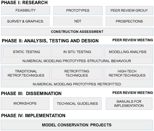
In phase 1, the SRP team identified and structurally assessed four (4) building typologies that are priorities for application of seismic retrofit techniques based on level of significance, where solutions are most needed, and which modes of failure and their reinforcement techniques will have the most widespread application in Peru and other countries in Latin America (Cancino et al. Citation2012). These were: the Temple of Santiago Apostol of Kuño Tambo, Ica Cathedral, Casa Arones, and Hotel el Comercio.
In phase 2, PUCP conducted an extensive laboratory testing campaign to characterize material properties and the behavior of the main structural systems (Vicente and Torrealva Citation2014). Finally, in-situ inspection and non-destructive tests (namely, sonic and dynamic identification tests) were performed by the University of Minho to evaluate the structural damage, the level of interaction between structural parts and the elastic properties of masonry (Lourenço, Karanikoloudis, and Greco Citation2016).
Subsequently, Finite Element (FE) models were developed and nonlinear static and dynamic analyses were conducted to investigate the structural response of the prototypes in terms of dynamic characteristics, lateral load capacity and failure mechanisms. The result obtained from the seismic assessment pointed out the need for strengthening measures for two of the prototype buildings: the Church of Kuño Tambo and Ica Cathedral. Information on Casa Arones and Hotel el Comercio have been published in Greco and Lourenço (Citation2016) and in Barontini and Lourenço (Citation2016), respectively. Structural damage was composed mainly from local out-of-plane failure modes, which were mainly activated by the lack of connectivity between structural parts. Detailed results have been published (Ciocci, Sharma, and Lourenço Citation2017; Karanikoloudis and Lourenço Citation2018).
Here, the strengthening design and assessment for the Church of Kuño Tambo and Ica Cathedral are discussed. Strengthening measures, according to conservation principles, were kept to the minimum necessary, to guarantee safety, durability, and the least damage to the historic fabric. Other factors influencing the design methodology adopted, included the state of the art research performed by GCI and PUCP on traditional, low-tech, yet highly effective, methods that have been used for retrofitting structures. Consequently, complementary laboratory tests were performed within the experimental campaign conducted by PUCP in order to investigate the behavior of the selected strengthening systems (Torrealva and Vicente Citation2014). Finally, the efficiency of the remedial techniques was evaluated through FE models.
A 3D macro-modeling FE approach was adopted for the adobe, fired brick, and base course stone masonry structural parts. Timber elements were modelled as beams, or as trusses when axial action was dominant. Nonlinear material laws were accounted for adobe masonry, brick masonry, and stone masonry (Ciocci, Sharma, and Lourenço Citation2017; Karanikoloudis and Lourenço Citation2018). A total strain rotating crack model, which accounts for compressive and tensile softening behavior was adopted, including the fracture energy concept (Lourenço Citation1998). As needed, in specified timber elements, a limitation in terms of force capacity was defined using the Von Mises yield stress criterion.
The proposed strengthening scheme included additional stiffness elements, but also measures for consolidation and increased durability. The main objective was to achieve high level of connectivity between structural parts, ensuring the so-called “integral behavior” (Lourenço et al. ). The strengthening scheme consisted mainly of internal and external bracing using timber elements, by means of bond beams, U-beams, tie beams, anchors, and corner keys, together with consolidation measures in damaged and deteriorated adobe and base course masonry parts. Additional capacity was provided by adobe buttressing (adequately tied with timber keys), partial replacement of adobe with fired brick pilasters and localized use of geogrid sheets, for protection against disproportionate collapse.
As part of phases 3 and 4, the SRP started the implementation of the seismic retrofitting plan in the Church of Kuño Tambo. Also, dissemination of the used methodology to design retrofitting techniques that can be implemented in earthen historic structures of similar typology, played a key role in SRP. Therefore, the GCI organized a set of workshops for midcareer professionals of the Ministry of Culture, held in Cusco and the Church of Kuño Tambo in August and November 2017.
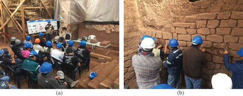
In the workshops, composed by theoretical and practical sessions, the participants (specialized masons, architects, engineers, archaeologists, sociologists and wall painting conservators) were exposed to the theory of conservation and a value-based approach to develop retrofitting projects. Practical issues of retrofitting techniques, such as the design of buttresses, the function of corner keys and interventions on the roof structure were also discussed and observed in situ. Field sessions were also organized, where the participants joined activities related to testing (i.e., thermographic imaging or sonic and dynamic tests) and to practical aspects of underpinning (). The concept related to historic mortars composition and performance was also approached, together with guidelines for the consolidation and cleaning of the wall paintings, such as those present in the Church of Kuño Tambo. Special emphasis was placed in the description of the mix used for the consolidating earth-based grout injections, by showing samples of different materials composing the mix. Similar workshops will be planned and then conducted at the Ica Cathedral when construction starts.
Figure 2. SRP workshop: (a) participants attending the non-destructive testing demonstration; and (b) participants applying different mixes of mortar on stone masonry
Seismic hazard in Peru and South America
The concept of seismic hazard is complex, involves entire continents, and is associated with immense socio-economic impacts. Peak ground acceleration (PGA) spatial distribution maps, with a 10% probability of exceedance within 50 years (i.e., a return period of 475 years), have been updated in many countries as existing knowledge increases and are part of national seismic codes. Currently, RNE E0.30 (Citation2016) divides the Peruvian country into four regions, assigning design values of PGA from 0.10–0.45 g, with the Church of Kuño Tambo and Ica Cathedral being in regions associated with a PGA of 0.25 g and 0.45 g, respectively.
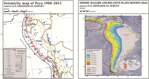
The rich tectonic activity of the South American coastal arc is characterized by the subduction of the Nazca plate beneath the South American plate, with the convergence extending over 7000 km. With rates of 65–80 mm/yr, the western edge of South America is under the influence of a rich volcanic and earthquake activity (). In the proximity of the subduction zone, in shallow depths of 10–60 km, interplate slips produce numerous large earthquakes with very high moment magnitude (Mw), often followed by devastating tsunamis (Hayes et al. Citation2014). As a result, Peru is one of the most active seismic areas of the world and the site of one of the largest known earthquakes, the 1868 Arica event (Mw 9.0). Recent significant earthquakes have shaken South central Peru, including the 2001 Arequipa and 2007 Pisco events with a moment magnitude of 8.4 and 8.0, respectively (Wong et al. Citation2012).
Figure 3. Seismic activity in South America: (left) historical earthquake database in Peru, for the period of 1900–2013 AD, with a magnitude range 5.5≤ Mw> 8.0, as compiled from the U.S. Geological Survey (Hayes et al. Citation2014); (right) seismic hazard map of 2014, with values of PGA in the range of 0–1.0 g and relative plate motion values (Hayes et al. Citation2014)
The 2007 Pisco earthquake occurred off the coast of Central Peru, with its epicenter located at approximately 110 km from Ica (13.35 S and 79.51 W), at a focal depth of 39 km (USGS). It caused severe damage to 58,581 houses and 13,585 additional houses were affected to some degree, with a total damage estimated of US$ 450 million (Taucer, Alarcon, and So Citation2009). Felt throughout much of the country, the cities of Pisco and Ica suffered the most. In Pisco nearly 80% of the adobe buildings were severely damaged and destroyed, while 32% of the historical and cultural monuments completely collapsed. In the city of Ica, 23% of the historic sites were affected by a high degree of damage, including Ica Cathedral (Blondet, Vargas, and Tarque Citation2008).
Seismic vulnerability of earthen historic structures
The seismic performance of masonry buildings is highly influenced by the redistribution of seismic forces between vertical elements, transferring out-of-plane loading in walls transversal to seismic action to in-plane loading in longitudinal walls, and is enhanced by additional bracing, offered by floors, ring beams, and joists (Lourenço et al. ).
Earthen historic structures mainly consist of heavy and thick walls, with corresponding high inertia forces. Buttressing and bracing systems are often found absent, insufficient, weakly connected or in poor condition. Given also the low mechanical properties (in tension and compression) and limited ductility of adobe, the overall structural response, under a seismic event, is not uniform and is characterized by low out-of-place capacity of individual structural parts (rigid blocks). The connections between orthogonal walls are therefore fragile and walls are subjected to early separation (Lourenço et al. ; Tolles Citation1996). Under a seismic action, structural damage patterns are associated with out-of-plane and in-plane failure modes, as shown in .
Figure 4. Failure mechanisms in earthen structures, induced by earthquakes: (a) collapse of the main façade due to rocking in the Church of Guadalupe, Ica 2007 (Cancino et al. Citation2011); (b) horizontal and diagonal shear cracks induced by rocking motion of independent structural parts in the church of Santísima Trinidad, Cusco 2014; (c) corner separation (Tarque Citation2008); (d) shear cracks near openings (Tarque Citation2008); (e) overturning failure of the corner of a lateral wall (Tolles Citation2006); and (f) out-of-plane overturning of entire adobe walls (Cancino et al. Citation2011)
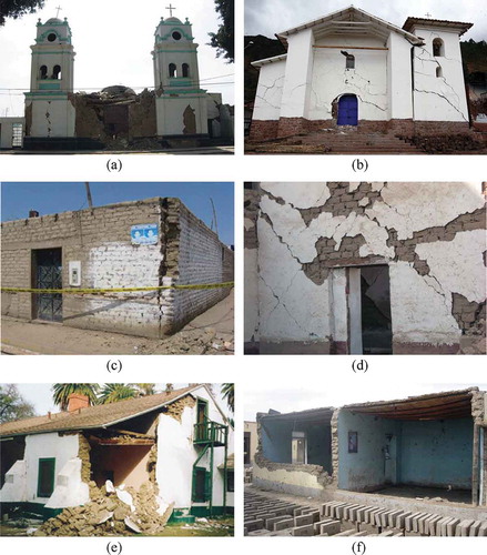
Out-of-plane failure modes involve unrestrained lateral walls of large spans. When the direction of the seismic loads is perpendicular to the wall’s main axis, horizontal flexural hinge lines are formed at the base or intermediate heights, together with vertical cracks close to the corners. Given the level of connectivity of intersecting walls, the presence of additional lateral restraint, out-of-plane mechanisms can involve smaller or larger portions of the walls (). The out-of-plane resistance of individual masonry walls is in direct relation to their slenderness ratio and, in some cases, the compressive strength in the area of the rotation axis (Tomaževič Citation1999). During the evolution of lateral loads, that area is often crushed (toe crushing) (617 C.S.LL.PP Citation2008; NTC Citation2008). Depending on the magnitude of the seismic action, the progression of damage in earthen buildings, with low and insufficient diaphragmatic stiffness, can be idealized as follows: connections between orthogonal walls are subject to early separation; horizontal flexural hinge lines are formed at rotation levels, at the base of walls or intermediate heights; lateral deformations close to mid-span increase continuously and corresponding flexural cracks progress in elevation and thickness; stresses in the compressed part of the rotation plane keep increasing; the material at the base is crushed under compression as part of the structure enters the softening phase; and crack patterns are united and large structural parts exhibit disproportional collapse modes at an exponential rate. In contrast, when bracing and confinement are provided, if out-of-plane failure modes occur, they are more ductile and consist of diagonal cracks due to bending at the corners and in the wall’s free span. Damage is more distributed in areas and higher lateral capacity values are reached (Lourenço et al. ).
Due to bending and shear, in-plane structural damage is characterized by horizontal, vertical, and diagonal cracks. Damage mechanisms (i.e., rocking, sliding, diagonal tension, and toe crushing) depend mainly on the geometry of the wall (height/width ratio and openings), boundary conditions, and compressive stresses. In cases of perforated earthen walls, many shear cracks are formed in the proximity of the openings and spandrels, being easily repairable. In-plane shear damage can also be the result of interaction between structural elements with different stiffness, such as the main facades of cathedrals, circumscribed between bell towers.
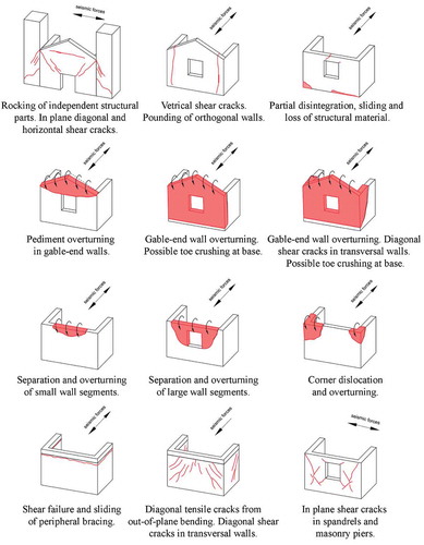
Lastly, partial disintegration and collapse of structural walls is also possible, whereas lack of maintenance and deterioration increase this possibility. Under the effect of seismic loads, many areas are subject to large displacement reversals, leading to partial disintegration of the material. Micro-cracks are intensified under long-term exposure to environmental agents and even sudden collapse in parts can occur (Angelillo, Lourenço, and Milani Citation2014; Karanikoloudis and Lourenço Citation2018). Typical structural damage patterns in earthen structures, under seismic forces, are given in .
Figure 5. Typical failure mechanisms in earthen structures
Assessment under current conditions
The Church of Kuño Tambo
The Church of Kuño Tambo is a religious structure of the 17th century, representative of churches built in the Andes during the Spanish Viceroyalty. It is a single nave church with an elevated presbytery and altar. Adjacent to the north side are the sacristy and baptistery. The walls and buttresses are of adobe masonry, having large thicknesses (1.6–1.9 m), with wall paintings on the interior finishes. The roof is a single gable timber roof, with layers of canes, mud, and straw, and clay roof tiles. The structure is built on a rubble stone base course plinth with earthen mortar, over a sloping natural rock, with varying layers of compacted clay (Cancino and Lardinois Citation2012).
The present damage appears to be inflicted partly by earthquakes and settlements, amplified by erosion due to improper drainage, lack of use and inadequate maintenance, and consequently abandonment. The system of six existing timber ties, along the span of the nave and altar, at eave level, is discontinuous and the level of confinement is poor. In the east façade, damage consists of vertical cracks at the corners, along the entire thickness and elevation. The south wall exhibits outward displacements, small cracks, and loss of material in exterior areas. Also, the baptistery exhibits several vertical cracks, located in the sidewalls and at the northeast corner. The dynamic behavior of the church, as identified from ambient vibration tests, is characterized by out-of-plane and out-of-phase bending modes, for the lateral and gable walls of the nave, as shown in (Lourenço, Karanikoloudis, and Greco Citation2016). These configurations demonstrate the low level of connectivity at the corners, which approximates true cracks, and the ineffectiveness of the existing tie beams.
Figure 6. The Church of Kuño Tambo: (a) selected capacity curves for the principal direction; (b) crack pattern of east facade (left) and gable-end wall of baptistery; (c) first mode shape from dynamic in-situ tests, with geometric interpolation; (d) FE model in 3D view; and (e) plot of maximum principal strain distribution at load step near collapse
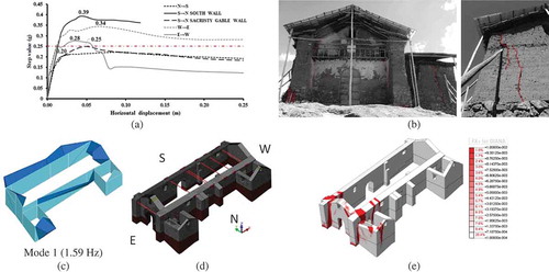
The dispersion of material properties, from literature, laboratory testing, and in-situ sonic testing was accounted by assigning them lower and upper bound values. shows the range of material properties with assigned nonlinearity. According to the pushover nonlinear analyses performed under a mass proportional lateral load, damage patterns are well correlated with the present damage and strengthening is needed in multiple directions, since the overall capacity does not reach the required peak ground acceleration (0.25 g), as shown in . (For more information see Karanikoloudis and Lourenço Citation2018.)
Table 1. The Church of Kuño Tambo: Mechanical properties of structural elements (Lourenço, Karanikoloudis, and Greco Citation2016)
Ica cathedral
The Cathedral of Ica is a highly complex structure, typical of churches erected in the urban coastal area of Peru during the Spanish Viceroyalty. Inspired by the Jesuits typology of the church of Gesu in Rome designed by Vignola, the rectangular plan consists mainly of a choir loft, a main nave, a transept, an altar, and two lateral aisles. Two sub-structures are evident: an external masonry envelope and an internal timber frame. The main façade built in a neoclassical style, is made of fired brick masonry with a thickness of 2.25 m and is flanked by massive bell towers on both sides. The lateral walls are of adobe masonry, over a base course constructed with fired brick and rubble stone masonry. The entire timber frame system, which is comprised by a series of pillars, pilasters, and a complex vaulted roof system, is made of Cedar, Sapele, and Huarango, with a traditional rendering technique of cane reeds nailed with leather strips, mud plaster, and gypsum, known as quincha (Ciocci, Sharma, and Lourenço Citation2017).
As previously mentioned, Ica Cathedral was affected by the 2007 Pisco earthquake which provoked partial collapse of the timber-vaulted roof system, as well as extensive cracking of the adobe walls. A later seismic event in 2009 (5.8 Mw) aggravated the already damaged condition with the collapse of the main dome.
According to Lourenço, Karanikoloudis, and Greco (Citation2016), the first experimental vibration mode (2.84 Hz) corresponds to the dominant mode in the transversal direction of the longitudinal side walls of the Cathedral (). Both the longitudinal walls of the nave experience a first order out-of-plane excitation with higher intensity in the northern wall, on the transept area. A model updating process was conducted considering only the masonry envelope, and the updated modulus of elasticity adopted for the different types of masonry are presented in , along with nonlinear parameters.
Table 2. Ica Cathedral: Mechanical properties of structural elements (Lourenço, Karanikoloudis, and Greco Citation2016)
Figure 7. Ica Cathedral: (a) Selected capacity curves for two principal directions; (b) crack pattern of east facade (right) and collapsed main dome and barrel vault (left); (c) first mode shape from dynamic in-situ tests, with geometric interpolation; (d) FE model in 3D view; and (e) plot of maximum principal strain distribution at load step near collapse
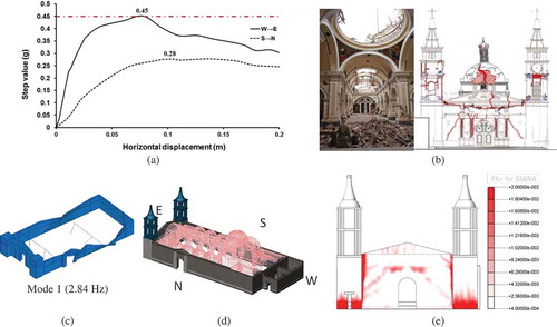
The structural behavior of Ica Cathedral is highly influenced by the connections between the external masonry envelope and the internal timber structure, resulting in a higher lateral capacity, when compared to the value obtained from the masonry envelope alone. Out-of-plane stiffness values at early stages are governed by the response of the timber sub-structure. Yet, high values of stresses were obtained for timber connections at ultimate limit state (ULS), justifying the partial collapse of the vaulted roof and the central dome. According to the pushover analyses carried out under mass proportional lateral load in the longitudinal direction, the out-of-plane failure mechanism, observed for the façade, corresponds to a lateral capacity of 0.45 g. Cracks in the pediment and at connection areas with the choir loft are well correlated with damage observed in-situ, as shown in . The out-of-plane capacity of the north lateral wall is 0.28 g, much lower than the capacity demand of 0.45 g for the region. Several flexural cracks were observed along the transversal adobe wall at the interface with the rubble stone base course, together with vertical cracks at the connection with the transept, confirming again the existing damage (Ciocci, Sharma, and Lourenço Citation2017) (Lourenço et al., Citation2017).
Traditional strengthening techniques
Philosophy, implementation, and guidelines
A strengthening plan has to align with conservation principles, namely minimal intervention, authenticity, and reversibility (ICOMOS Citation2003). The strengthening philosophy and implementation, through traditional techniques, is long proven and present in many historic earthen buildings, although often disregarded in current strengthening practices. It involves the combination of additional elements, such as buttresses and bracing elements, i.e., corner keys, horizontal keys, bond beams, and anchored tie beams. Material compatibility, consolidation, and sufficient care in timber connection details are also of importance. Many practices are already incorporated, as parts of guidelines and recommendations, in seismic building codes and standards for new earthen buildings, such as Peru, Nepal, India, and New Zealand ().
Table 3. List of technical norms and national codes for the design and evaluation of earthen buildings and strengthening components
Repair measures mostly involve the replacement of highly deteriorated adobe and base course masonry parts. The extent of replacement should be clarified from damage mapping and limited, so as to preserve the historic fabric. Interlocking between old and new masonry parts should also be properly established. Reestablishment or the addition of buttresses can efficiently address low or compromised out-of-plane capacity and minimize lateral deflections, especially in walls of large spans. The design verification of buttressing, in terms of size, number, and covering span, can be easily performed with simple analysis tools, such as limit analysis (617 C.S.LL.PP Citation2008; NTC Citation2008). Even if current design guidelines for buttresses in new earthen construction, regarding the spacing, are more suitable for slender walls, a minimum thickness and length, equal to the thickness of the adjoining wall, is recommended (IS 13827 1993). Connectivity between the existing earthen walls and the new buttresses can be ensured by inserting horizontal timber elements at various heights.
For ensuring connectivity in corners between orthogonal walls, orthogonal or diagonal timber keys can be used (Ortega et al. Citation2017). The insertion should be made at horizontal planes of various elevations, involving mostly the upper parts of walls. For existing cracks, several processes are applicable, such as partial replacement of material, stitching, repointing, and grout injections, with earth-based grouts (Silva et al. Citation2014).
Additional lateral restrain, in the case of longitudinal parallel walls, can be offered by means of tie beams. Such a system should be placed at the level of the top eaves, embedded favorably along the thickness of the walls. These elements are subjected to both tension and compression, given the dynamic nature of seismic loads. Thus, an adequate anchoring system is needed and, usually, a double system of vertical timber anchors, attached to the interior and exterior surfaces of each wall, is proven effective.
Last, the implementation of an internal horizontal timber frame system, located at the top level and passing throughout the whole thickness of earthen walls, can enhance substantially the capacity under lateral forces (Cancino et al. Citation2016; Ortega et al. Citation2017; Tomazevic Citation1999). This bond-beam or U-beam can also serve as support system for roof rafters (wall plates). Moreover, the whole system can be connected with a system of tie beams, plates, and anchors, forming a combined internal and external timber frame system. For the tying system to perform efficiently, timber elements need to be confined in masonry and subjected to normal vertical stresses, from overlapping masonry parts and roof loads, so that friction or shear action is available (Tomazevic Citation1999).
Many of the above-mentioned strengthening techniques were implemented in the Church of Kuño Tambo and Ica Cathedral, with detailing schematics, as shown in and .
Figure 8. Detailing of traditional strengthening techniques, implemented in the Church Kuño Tambo: (a) cross section of new buttress, with horizontal timber keys, new interlocking, and geo-mesh; (b) detail of horizontal timber key between buttress and adjoining wall, with vertical key anchors to enhance connectivity (in red); (c) timber embedded corner keys in elevation and continuous bond beam at top eave; (d) detail of combined timber frame system, with bond beam, tie beam and vertical timber anchors; (e) timber embedded elements in elevation and horizontal planes; (f) and (g) implementation of timber keys in new adobe buttress during construction phase; and (h) implementation of tie beams and bond beam system, during the constructions phase (‘Kuñotambo’ Citation2017)
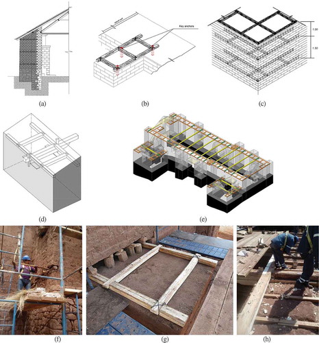
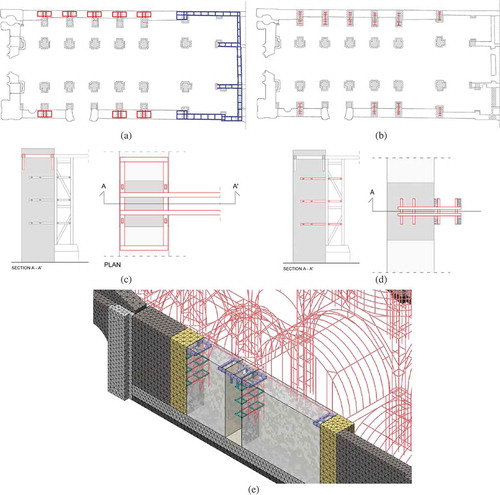
Figure 9. Detailing of traditional strengthening techniques, implemented in Ica Cathedral: (a) U-beam at top eaves, in parts with low out-of-plane resistance, configuration with two longitudinal timber beams and transversal timber blockers (in blue). Upper anchoring system in the lateral wall of the nave (in red); (b) lower anchoring system in the lateral wall of the nave (in red); (c) connection between masonry wall and timber floor. Tying system with tie beams, vertical and horizontal timber anchors; (d) connection between masonry wall and timber pillar, with horizontal timber anchors; and (e) configuration embedded timber strengthening elements, in 3D view
Decision process through a principle-based matrix
The decision process to conclude on specific retrofitting techniques to be performed on a historic earthen structure is case dependent and complex. Many retrofitting techniques, can be accounted as more efficient, matching closely with local practices, material availability, technical skills, and available equipment. In case of decorative assets, such as wall paintings, the decision on strengthening measures is much more complex. Also, preserving authenticity can be in conflict with high levels of structural safety. In order to account all the above, an integrated approach, specifically oriented for a multidisciplinary group of experts, was developed in the SRP, through a principle-based matrix. Here, guiding principles, strengthening solutions and architectural values are paired and prioritized, according to conservation principles, technical specifications, and economic restrictions (Cancino et al. Citation2016).
For the Church of Kuño Tambo and Ica Cathedral, the principle-based matrix is dichotomized with conservation and engineering principles. Conservation principles involve mostly minimal intervention, reversibility, authenticity, and maintenance. Engineering principles are grouped in aspects of structural and human safety, durability, feasibility, and economic viability. For each conservation/retrofitting decision and pair of principles, the project team assigned relative importance factors. After reaching consensus, each principle is given a number, the sum of the relative importance factors. In Ica Cathedral, the strengthening of the north lateral wall, with the addition of brick masonry pilasters within the volume of the adobe wall, prevailed over the principle of minimal intervention, because higher importance was given to safety (). In the case of the Church of Kuño Tambo, the high relative importance of the wall paintings, in terms of authenticity, defined the engineering decision on the implementation of corner keys only from the exterior side of the adobe walls. Moreover, it forced the conservation team to decide on pre-consolidating the paintings, in order to minimize any effect during the implementation of the strengthening ().
Figure 10. Principle-based matrix for conservation and engineering principles. Implementation for: (a) Ica Cathedral; and (b) the Church of Kuño Tambo (Cancino et al. Citation2016)
Evaluation through pull-out capacity tests
An extensive laboratory testing campaign on material characterization and capacity of individual strengthening elements was also conducted by the Pontificia Unviersidad Católica del Perú (PUPC, Pontifical Catholic University of Peru), within the framework of the SRP project (Vicente and Torrealva Citation2014).
A key issue on the concept of strengthening implementation is to understand the interaction and potential failure mechanism of an earthen-timber composite structure. The introduction of a single timber tie, anchored externally in an adobe wall, activates the masonry in a combination of shear and tensile stresses. Given the assumption that the anchoring is strong enough to withstand failure, the predominant failure mechanism is the tensile failure of adobe masonry in a plane of about 45°, surrounding the tie-anchor system, known as cone failure (Vinci Citation2014). In case of more embedded elements, forming a timber frame, as in the case of timber keys, placed in various heights of intersecting walls, the cone covers a wider area. Results from pull-out tests on timber ties and orthogonal timber keys, anchored in adobe masonry wallets of various thicknesses, conducted at PUCP (Torrealva and Vicente Citation2014), show the formation of cone failure and justify the above reasoning.
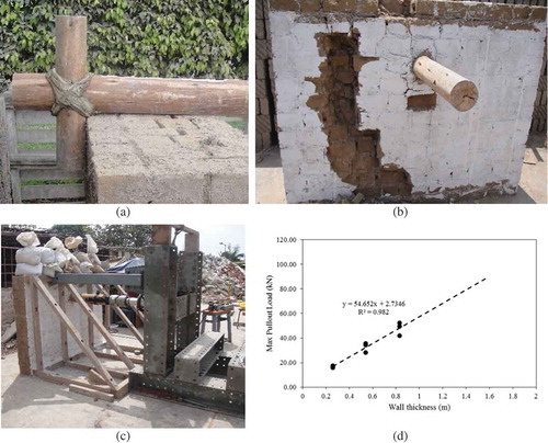
As shown in , a single tie beam (diameter Φ17.8 cm) is anchored externally with a vertical key 55 cm long (Φ10.2 cm) in adobe wallets of varying thickness, within a range of 26–83 cm. The results from pull-out tests on single timber ties, exhibit a linear regression and the capacity depends on the thickness of the adobe wall specimen (). Yet, in reality, earthen walls in parallel configuration, connected with a system of timber ties, will behave much differently: the ties will be activated mainly due to the relative stiffness between the lateral walls and, given the boundary conditions, the confinement level of timber ties, the pull-out capacity and cone failure will never be obtained. Instead, a combination of flexural cracks at mid height and vertical separation cracks will dominate the response and potential failure.
Figure 11. Experimental results on pull-out tests from PUCP: (a) tie beam and anchor of testing assembly; (b) cone failure; (c) pull-out testing procedure; and (d) maximum pull-out test results versus wall thickness, and linear regression trend (Torrealva and Vicente Citation2014)
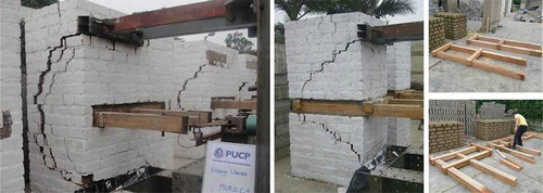
In the case of pull-out tests in adobe wallets with embedded orthogonal timber keys, the cone failure is extended around the timber frame. Here, main beam sections are 12.5x12.5 cm, while the thickness of the wall is 80 cm. As shown in , two different testing assemblies replicate the orthogonal timber key, between two transversal adobe walls. Maximum pull-out capacity was obtained within a range of 27–37 kN. In reality, one cone failure will be formed in the part with the weakest connection.
Figure 12. Experimental results on pull-out tests from PUCP: (a) tie beam and anchor of testing assembly; (b) cone failure; (c) pull-out testing procedure; and (d) maximum pull-out test results vs. wall thickness, and linear regression trend (Torrealva and Vicente Citation2014)
Assessment under strengthening
Both case studies, under the implemented strengthening scheme presented in and , were assessed under mass proportional lateral loading in principal directions. Nonlinearity was accounted for all introduced masonry typologies. For selected timber strengthening elements, bounds of sectional resistance were calculated considering tension and compression at yield and buckling, and were assigned by a Von Mises yield stress criterion. Here, it needs to be stressed that for the assessment of strengthening, as well as for the current state, nominal values of material properties were used. The process of addressing seismic vulnerability and strengthening in historic structures needs to be based on average values of strength or at least lower partial safety factors rather than those used for modern structures (Tomaževic and Lutman Citation2007). Otherwise, the design is bound to be conservative, leading to excessive and even unnecessary strengthening measures.
Church of Kuño Tambo
In November 2017, the strengthening and rehabilitation project for the Church of Kuño Tambo, as developed within the SRP, started its implementation by the Dirección Desconcentrada de Cultura – Cusco, a branch from the Ministry of Culture of Peru (‘Kuñotambo’ Citation2017).
Three new adobe buttresses, with rubble stone base, were designed for the south lateral wall of the nave. From applicable kinematic mechanisms under horizontal equivalent seismic forces, the maximum capacity, for the ULS, is 0.32 g, higher than the PGA demand for the Cusco region of 0.25 g (NTE-0.30 2016). For each buttress, horizontal timber keys are placed, in three elevations, at a distance of 1.50 m, with the middle tie placed at mid height of the adobe masonry. Timber keys are inserted until half the thickness of the lateral walls and are configured as shown in . The buttresses are partly wrapped with geogrid sheets, in order to prevent disproportional collapse under seismic loads.
On the top eaves of the walls and in the corner junctions, timber embedded elements are placed, in order to enhance connectivity and deformability, using orthogonal bond beams and corner keys, respectively. Both elements are inserted either from upper or exterior parts of the walls, by removing adobe courses, and are composed by two sets of timber beams, connected transversally with timber blockers. The bond beam and the two orthogonal corner keys were inserted according to the configuration presented in .
Last, a system of eleven tie beams was designed to offer lateral restraint, mostly to the weak south lateral wall of the nave. A double vertical anchoring system was designed, attached to the interior and exterior surfaces of the walls, which proved efficient under tension and compression, and fulfilled the criteria described above for the decision process. In order to increase the anchoring and pull-out capacity of the system, the tie beams are connected to the overlying bond beams ().
The chosen timber species for the strengthening elements are Eucalyptus Globulus, with strength values of timber class B (RNE E.10 2006). It is important to mention that all timber connections are designed as half-lapped pinned connections, with leather straps, chosen from traditional local practices. A square section of 20 × 20 cm2 is chosen for the tie beams, while for the bond beam, horizontal and orthogonal timber keys, elements with 15 × 15 cm2 section are chosen. The anchors are placed as wedges, in holes made at mid-section of the tie beams. Their upper section 7.6 x 15.2 cm2 and the lower is 7.6 x 7.6 cm2. Their length varies from 80–90 cm.
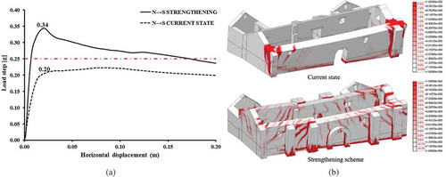
Due to the addition of new buttresses and timber frames, the structure presents a stiffer response, with a shift towards higher frequencies. The first out-of-plane mode for the lateral walls of the nave is now 4.41 Hz (eigenvalue analysis), vs. 1.59 Hz in the current state (dynamic tests). Nonlinear pushover analyses, under mass proportional lateral loading, were performed in all principal directions and the overall performance has greatly improved. The redistribution of seismic loads between transverse and longitudinal walls is now ensured, and the capacity reached is higher than the design requirement from the Peruvian seismic code, with a minimum safety margin of 1.5. In the direction of the weakest capacity (N→S), the strengthening scheme presents a substantial higher capacity of 0.34 g, increased by 70%, compared to that of the current state. As shown in , an evident change on the failure mechanism occurs from the out-of-plane overturning of the entire south wall. The bond beams, corner keys and buttresses increase the stiffness and allow the lateral walls to deform in out-of-plane bending, while activating the transversal walls. Cracking at a load step near collapse, is more widely spread, with smaller crack widths, compared to the large cracks of almost 10 cm of the current state (Karanikoloudis and Lourenço Citation2016).
Figure 13. The Church of Kuño Tambo: (a) load-displacement diagram, at the top of the south wall. Note the seismic demand of 0.25 g (in red); and (b) distribution of maximum principal tensile strains for 20 cm of lateral displacement for the model at current and strengthening state. (Note that the results are from the numerical models with material properties updated by in-situ sonic tests.)
Ica Cathedral
For Ica Cathedral, the strengthening proposal includes mainly the replacement of existing masonry with new brick masonry in selected parts of the structure, timber anchoring systems, and a timber collar beam.
A new brick masonry wall was proposed at the north-western corner of the structure, connected to the adjacent existing walls by proper interlocking. Moreover, new brick masonry columns were recommended at the location of every connection between the internal timber structure and the masonry envelope, along the longitudinal walls. Embedded in these new brick masonry columns, timber anchoring systems were proposed to improve the connection between the two sub-structures. As shown in , each timber anchoring system is composed of keys and ties, which are connected by means of half-lap joints with nails. Located at four levels along the height of the walls, the timber members at the lower levels have a cross section of 7.5 x 7.5 cm2, while a cross section of 15 × 15 cm2 is adopted for the elements at the higher level. In order to improve the resisting mechanism, vertical keys embedded downward in new brick masonry were also proposed at the uppermost level of the anchoring system. shows the U-shape timber collar beam which was proposed to be located at the back of the structure. It is composed of timber elements with a cross section of 15 × 15 cm2 which are joined with nailed or pegged half-lap connections. Finally, it should be mentioned that a steel anchoring system was also proposed to improve the connection between the front façade and the internal timber structure. More details can be found in Ciocci, Sharma, and Lourenço (Citation2017b).
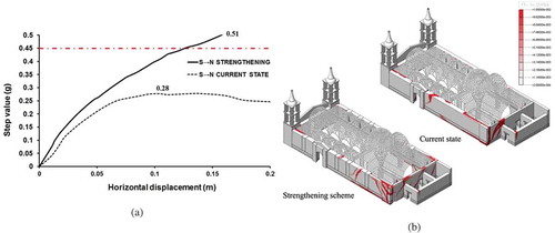
The results obtained from the pushover analysis performed applying mass proportional loading in the N→S direction show a ductile progression of flexural cracks in the northwestern corner (). The value of lateral load that could be applied to the model is higher than the seismic demand recommended for the region of Ica, with an increase of more than 60% when compared to the current state. In the other direction, the lateral capacity increases by 15% when compared to the current state, reaching a value equal to 0.45 g. The failure mechanism is identified in this direction is the out-of-plane overturning of only the southern bell tower, replacing the out-of-plane overturning of the whole front façade including the bell towers that was observed for the model without strengthening. As a result, the implemented strengthening techniques, which mostly improve the quality of the connections between the two sub-structures, reduce effectively the out-of-plane vulnerabilities and increase the capacity of the structure, higher than the seismic demand.
Figure 14. Ica Cathedral: (a) load-displacement diagram, at the top of the north wall. Note the seismic demand of 0.45 g (in red); and (b) distribution of maximum principal tensile strains for 20 cm of lateral displacement for the model at current and strengthening state
Conclusions
Historic earthen structures are a significant portion of the built heritage worldwide, with similarly identified structural characteristics and performance levels. In areas with high seismic hazard and in the absence of bracing and buttressing, these structures are usually characterized by structural discontinuities, low lateral capacity, and potent fragmentations in corner junctions. Given their low mechanical properties, usual lack of maintenance and structural alterations, historic earthen structures are bound to perform inadequately in strong earthquakes, in the absence of corrective measures.
Based on recommendations from national building codes, conservation principles and local practices, traditional strengthening techniques can improve the integrity of earthen structures, increase the out-of-plane capacity and redistribute seismic loads between transversal and longitudinal walls, ensuring the so called “integral behaviour”. Commonly used, traditional strengthening techniques involve the use of buttresses, together with systems of timber strengthening elements, such as bond beams, anchors, corner keys, and tie beams.
Under the Seismic Retrofitting Project of the Getty Conservation Institute, extensive inspections, surveys, in-situ and laboratory testing, and nonlinear structural analyses of earthen historic structures assessed the current state revealing structural deficiencies. For two case studies, the Church of Kuño Tambo and Ica Cathedral, a complete design and assessment of the above-mentioned strengthening solutions have been carried out, and the project methodology and the resulting retrofitting techniques are currently being disseminated for local practitioners in Peru. The strengthening proposal was developed by a multidisciplinary team, involving national and international engineers, architects, and cultural heritage authorities. For the retrofitted structures, performance criteria and seismic local demands were met, with sufficient safety and acceptable levels of repairable damage. Furthermore, energy dissipation under lateral loading increased and a better redistribution of seismic loads between transverse and longitudinal walls was achieved.
Acknowledgments
This work was carried out with funding from the Getty Conservation Institute (GCI) as part of its Seismic Retrofitting Project. This work is also partially financed by FEDER funds through the Competitivity Factors Operational Programme - COMPETE and by national funds, through FCT – Foundation for Science and Technology, within the scope of the projects POCI-01-0145-FEDER-007633 and UID/ECI/04029/2013.
Notes
1 This technical norm–commonly known as Norma del Adobe—was created to regulate seismically resistant new adobe constructions and was added for the first time to the Peruvian National Building Code in 1977. The NTE-80 was originally designed by a group of architects and engineers who were members of the Norma del Adobe committee (NORMA) created at the Servicio Nacional de Capacitación para la Industria de la Construcción (SENCICO — National Service Training for the Construction Industry). SENCICO is a governmental agency part of the Ministry of Housing and Construction that among its functions develops norms, standards, and regulations for building design, construction materials and technologies in order to improve construction quality, costs, and live safety assurance. The NTE-80 was reviewed for the first time in 1999 and is currently expanded to include a section on interventions on historic earthen buildings.
References
- 617 C.S.LL.PP 2008. Istruzioni per l’applicazione delle «Nuove norme tecniche per le costruzioni», Ministero delle Infrastrutture, Rome, Italy, (in Italian)
- Angelillo, M., P. B. Lourenço, and G. Milani 2014. Masonry behaviour and modelling. Mechanics of Masonry Structures CISM International Centre for Mechanical Sciences Volume 551, doi:1-26.(doi:10.1007/978-3-7091-1774-3_1)
- Barontini, A., and P.B. Lourenço 2016. Seismic Assessment of Hotel El Comercio (Current Conditions), Peru, Report 2016-DEC/E-10, Universidade do Minho – TecMinho, Guimaraes, Portugal
- Blondet, M., J. Vargas, and N. Tarque 2008. Observed behavior of earthen structures during the Pisco (Peru) earthquake of August 15, 2007. In: proceedings of the 14th world conference on earthquake engineering, 14WCEE, Beijing, China. (http://www.iitk.ac.in/nicee/wcee/article/14_01-1031.PDF)
- Cancino, C. 2011. Damage assessment of historic earthen buildings after the August 15, 2007, Pisco, Peru earthquake. Los Angeles, CA: Getty Conservation Institute. http://hdl.handle.net/10020/gci_pubs/damage_assessment.
- Cancino, C., D. Torrealva, E. Vicente, J. García Bryce, M. Soto, E. Cruz, and K. Wong 2016. The cathedral of Ica and the church of Kuño Tambo in Peru: Two retrofitting projects following a principles-based conservation approach, structural analysis of historical constructions: Anamnesis, diagnosis, therapy, controls, Proceedings of the 10th International Conference on Structural Analysis of Historical Constructions, SAHC 2016, pp. 410–17.
- Cancino, C., and S. Lardinois. In collaboration with D’ Ayala, D., Fonseca Ferreira, C., Torrealva Dávila, D., Vicente Meléndez, E., Villacorta Santamato, L, 2012. Seismic retrofitting project: assessment of prototype buildings. 2 vols. Los Angeles, CA: Getty Conservation Institute. http://hdl.handle.net/10020/gci_pubs/assess_prototype.
- Ciocci, M. P., S. Sharma, and P. B. Lourenço 2017b. Ica Cathedral, Peru: Safety assessment and strengthening. Proceedings of the 13th Canadian Masonry Symposium, 13CMS, Halifax, Canada.
- Ciocci, M.P., S. Sharma, and P.B. Lourenço 2017. Engineeringsimulations of a super-complex cultural heritage building: IcaCathedral in Peru, Meccanica Volume 53(7),1931-1958. (doi:10.1007/s11012-017-0720-3)
- Greco, F., and P. B. Lourenço. 2016. Seismic assessment of casa arones (current conditions), Peru. Report 2016-DEC/E-08, Portugal: University of Minho.
- Hayes, G. P., G. M. Smoczyk, H. M. Benz, A. Villaseñor, and K. P. Furlong. 2014. Seismicity of the Earth 1900–2013, seismotectonics of South America (Nazca plate region). US: U.S. Department of the Interior, U.S. Geological Survey.
- ICOMOS. 2003. ICOMOS charter- principles for the analysis, conservation and structural restoration of architectural heritage. Charenton-le-Pont, France: International Council of Monuments and Sites.
- IS 13827:1993 1993. Improving earthquake resistance of earthen buildings: Guidelines. New Delhi: Bureau of Indian Standards.
- Junta del Acuerdo deCartagena PADT- REFORT’. 2000. Manual de diseño para maderasdel grupo andino, Lima, Peru. (in Spanish).
- Karanikoloudis, G., and P. B. Lourenço. 2016. Seismic assessment of Kuño Tambo Church (strengthening proposal), Peru. Report 2016-DEC/E-10, Portugal: University of Minho-TecMinho, Guimaraes.
- Karanikoloudis, G., and P. B. Lourenço 2018. Structural assessment and seismic vulnerability of earthen historic structures, Application of sophisticated numerical and simple analyticalmodels. engineering structures. 160, 488-509. (doi:10.1016/j.engstruct.2017.12.023).
- Kuñotambo’ 2017. Seismic Retrofitting Project. Case Study: Kuñotambo, Getty ConservationInstitute. (http://www.getty.edu/conservation/our_projects/field_projects/seismic/case_study_kunotambo.html)
- Lourenço, P. B., G. Karanikoloudis, and F. Greco 2016. In-situ testing and modeling of cultural heritage buildings in Peru. Proceedings of the 10th International Conference on Structural Analysis of Historical Constructions, SAHC 2016, pp. 850–57.
- Lourenço, P. B., N. Mendes, and L. F. Ramos, and D. V. Oliveira 2011. Analysis of Masonry Structures Without Box Behavior,International Journal of Architectural Heritage, 5: 4-5,369-382,(DOI: 10.1080/15583058.2010.528824)
- Lourenço, P. B., S. Sharma, M. P. Ciocci, F. Greco, and D. V. Oliveira 2017. Seismic assessment of a complex earthen structure: Ica Cathedral (Peru), Proceedings of the 16th World Conference on Earthquake Engineering, 16WCEE.
- Lourenço, P.B. 1998. Experimental and numerical issues in themodelling of the mechanical behavior of masonry. Proceedings ofthe 2nd International Seminar on Structural Analysis of HistoricalConstructions, International Center for Numerical Methods inEngineering, Barcelona, Spain.
- NBC 204 1994. Nepal NationalBuilding Code - Guidelines for earthquake resistant buildingconstruction in earthen buildings, Kathmandu, Nepal.
- NTC 2008. Nuove norme tecniche per le costruzioni e circolare esplicativa. Decreto Ministeriale Infrastrutture 14 gennaio 2008-Circolare 2/02/2009 N°617/C.S.LL.PP. DEI, Roma. (in Italian)
- Ortega, J., G. Vasconcelos, H. Rodrigues, M. Correia, and P. B. Lourenço. 2017. Traditional earthquake resistant techniques for vernacular architecture and local seismic cultures: A literature review. Journal of Cultural Heritage. doi:10.1016/j.culher.2017.02.015.
- RNE E.010 2006. Reglamento nacional de edificaciones: Norma técnica E.010 “Madera”. Decreto Supremo N° 011-2006-vivienda (05 Mar 2006). Ministerio de Vivienda, Construcción y Saneamiento, Peru. (in Spanish)
- RNE E0.20 2006. Reglamento Nacional de Edificaciones: Norma Técnica E.020 “Cargas”. Decreto Supremo N° 011-2006-vivienda (05 Mar 2006). Ministeriode Vivienda, Construcción y Saneamiento, Peru. (in Spanish)
- RNE E0.30 2016. Reglamento nacional de edificaciones: Norma tecnica E.030 “Diseño sismorresistente”. Decreto Supremo N° 003-2016-vivienda (24 Jan 2016). Ministerio de Vivienda, Construcción y Saneamiento, Peru. (in Spanish)
- Silva, R. A., D. V. Oliveira, L. Schueremans, T. Miranda, and J. Machado 2014. Shear behaviour of rammed earth walls repaired by means of grouting, Proceedings of the 9th International Masonry Conference, IMS.
- Tarque, S. N. 2008. Seismic risk assessment of adobe dwellings. Master Thesis, University of Pavia, Italy.
- Taucer, F., J. Alarcon, and E. So. 2009. 2007 August 15 magnitude 7.9 earthquake near the coast of Central Peru: Analysis and field mission report. Bulletin of Earthquake Engineering 7(1):1–70. doi:10.1007/s10518-008-9092-3.
- Tolles, E. L. 1996. Survey of damage to historic adobe buildings after the January 1994 Northridge earthquake. Los Angeles, US: Getty Conservation Institute.
- Tolles, E. L. 2006. Seismic retrofit applications of getty seismic adobe project technology to historic adobe buildings, Proceedings of the Getty Seismic Adobe Project 2006 Colloquium, The Getty Conservation Institute, Los Angeles, US.
- Tomaževič, M., and M. Lutman. 2007. Heritage masonry buildings in urban settlements and the requirements of eurocodes: Experience of Slovenia. International Journal of Architectural Heritage 1(1):108–30. doi:10.1080/15583050601126186.
- Tomazevic, M. 1999. Earthquake-resistance design of masonry buildings. London: Imperial College Press, (Series on innovation in structures and construction).
- Torrealva, D., and E. Vicente 2014. Experimental behaviour of traditional seismic retrofitting techniques in earthen buildings in Peru. Proceedings of the 9th International Conference on Structural Analysis of Historical Constructions, SAHC 2014,Mexico City, Mexico.
- Vicente, E. F., and D. E. Torrealva 2014. Mechanical properties of adobe masonry of historical buildings in Peru. Proceedings of the 9th International Conference on Structural Analysis of Historical Constructions, SAHC 2014, Mexico City, Mexico.
- Vinci, M. 2014. I tiranti in accaio nel calcolo delle construzioni in muratura. in Italian, Palermo, Italy: Dario Flaccovio Editore.
- Wong, I., M. Dober, S. Pezzopane, P. Thomas, and F. Terra 2012. Seismic hazard above the south america subduction zone in Southern Peru. Proceedings of the 15th World Conference on Earthquake Engineering, 15WCEE, Lisbon, Portugal.