
 ?Mathematical formulae have been encoded as MathML and are displayed in this HTML version using MathJax in order to improve their display. Uncheck the box to turn MathJax off. This feature requires Javascript. Click on a formula to zoom.
ABSTRACT
Concerning strengthening techniques for existing masonry walls, the trend is toward the use of Fibre Reinforced Mortar (FRM) with both a significant increase of the mortar strength, and a drastic thickness reduction of the added external layers. In the present analysis, the focus is posed on some new lime mortar types which possess a very high strength in tension, although the elastic modulus remains in a normal range, leading so to a considerable toughness increase. The G-FRM system is composed with a glass fibre mesh which must possess a tensile resistance larger than the one of the mortar area including it, and this allows introducing some ductility in the composite. A total of 14 diagonal compression tests of masonry walls reinforced with G-FRM have been completed at LISG (Structural Engineering and Geotechnics Laboratory, University of Bologna), encompassing different FRM combinations. More precisely, the walls were reinforced with three different lime mortar compounds with layer thicknesses of 12, 15 and 30 mm, and reinforced with two different glass fibre meshes and two different arrangements of steel micro-wire strips. The performed tests showed that the interpretation of the observed behaviour needs a sound theoretical basis of the experimental setup, avoiding the simple analysis reported in standards and codes. A finite element model of the experimental setup was prepared, able to identify the features of the observed behaviour. Following this suggestion, a new theoretical model based on Mohr-Coulomb plasticity was defined and applied to the interpretation of a large database of experimental tests with a very good agreement.
1. Description of the work
The earthquake mitigation in central Italy requires the exploitation of techniques able to increase the shear strength of weak masonry walls, while maintaining the architectural features and the ecologic nature of the historic brick and stone constructions. Furthermore, advances in conservation philosophy deny any drastic change of behaviour of existing monuments, so that very high strength materials and very stiff additions are considered unsuitable.
Among the many remaining possibilities, the use of thin structural coatings or plasters, made with high strength lime mortars obtained from natural binders cement free, and reinforced with meshes composed with non-corrodible materials, is steadily increasing its market share and importance.
This combination, indicated with the acronym FRM (fibre-reinforced mortar), actually has evolved in a practically cement free material and has a very high compatibility with ancient masonry. It is used as a structural coating for masonry walls, with thickness in the range 10–30 mm on each face, and in general contains meshes or unidirectional strips of non-corrodible compatible fibre such as basalt, glass, or stainless steel. The two layers of FRM reinforcing the faces of a wall are in general fastened through the wall thickness by means of connectors produced with glass fibre ropes or bundles of steel micro-wires.
In the present investigation carried out at the LISG Laboratory in the University of Bologna, three types of mortars were tested, with three different reinforcement solutions. In detail, the mortars included the reference mortar used in composing the walls (REF), two high strength mortars (BTF, BTG) and one high adhesion mortar (BTC). All the mortars were provided by Weber Company, are a premixed product complying with REACH rules and contain mainly NHL 5.0 lime, pozzolanic cement, sand, additives.
The studied reinforcements were two different glass fibre meshes (GA and GB), and a steel unidirectional micro-wire strip (SS). The mortar compressive strength was in the range 10–15 MPa, while the used reinforcement materials were chosen in order to satisfy a strength hierarchy criterion with stable behaviour after mortar cracking.
In the paper, the experiments are discussed in detail in order to set out a rational procedure for the interpretation of the tests. Since the proposed procedure does not contain any experimentally derived or interpolated factor, it is then tested against two wide experimental investigations discussed in the literature.
The very good prediction capability of the presented formulas points out the significance of the procedure as a basis for a reinforcement rational design.
2. Short historic notes of the use of FRCM and FRM composites
The idea of a thin cement layer containing a reinforcing mesh is dating back to the birth of reinforced concrete, as it was patented by Joseph Monier in 1867 (Adams and Matthews Citation1911). This idea, which is at the basis of FRM and FRCM coatings too, was later expanded and advanced by Pier Luigi Nervi with his famous “ferrocement” (Nervi, Citation1965).
One of the first proposals of mesh-reinforced coatings as viable seismic mitigation systems was presented by Jabarov, Kozharinov, and Lunyov (Citation1980). Diagonal compression tests of masonry panels with ferrocement reinforcing layers were presented by Prawel, Reinhorn, and Qazi (Citation1988).
At the beginning of the twenty-first century, a rapid change of technology introduced the new high performing fibre materials such as carbon and glass-reinforced polymers (FRP, see for instance CNR DT 200/2004, Citation2004). In the case of masonry walls however, thermo-hygrometric reasons promoted the use of inorganic binders in place of organic resins, with techniques more conforming to the Venice Charter of 1964 (ICOMOS Citation1965).
Many research groups developed extensive investigations both experimental and theoretical on shear resistance of masonry panels reinforced with externally bonded thin layers of fibre mesh-reinforced mortars; among the most recent contributions Babaeidarabad, De Caso, and Nanni (Citation2014) and Gattesco and Boem (Citation2015) presented formulas for the design of FRM reinforced masonry panels based on a combination rule of the masonry and reinforcement shear capacities. Garofano, Ceroni, and Pecce (Citation2016) presented finite element models for the analysis of the strengthened panels. Kouris and Triantafillou (Citation2019) developed formulas for the in-plane and out-of-plane design.
The failure modes of masonry panels strengthened with FRM coatings are mainly of two types: the mortar undergoes cracking and then the fibres connecting the crack faces fail in tension, or the coatings detach from the masonry in a way similar to composite debonding. The second failure mode is brittle and must be avoided, and therefore normally the coatings are connected through the wall by means of fasteners.
Thus, a very important complementary research line is considering the characterization procedures for the tensile capacity of the fibre-reinforced material. The main problem is the set-up of the tensile test allowing for the better definition of the reference values to be used in the design. This topic has been discussed in depth by Arboleda et al. (Citation2015), Donnini and Corinaldesi (Citation2017), and Gattesco and Boem (Citation2017).
In what follows the data presented by Gattesco and Boem (Citation2015)and Gattesco, Boem and Dudine (Citation2015) will be used as an independent check of the proposed interpretation of the FRM reinforced masonry panels under diagonal loading. The comparison shows clearly the high predictive capability of the proposed theory.
3. Material characterization and specimen preparation
3.1. Characterization of the materials
The experimental evaluation of the material mechanical properties was performed in agreement with the EN 1015-11:2007 (Citation2007) and EN 1015-12:2002 (Citation2002) procedures by casting mortar prisms of 40 · 40 · 160 mm3 and mortar reinforced plates of thickness less than 10 mm and size 100 · 500 mm2. In addition, direct tensile tests of the fibre glass wires were executed in order to examine the nominal properties indicated by the producer. Some non-standard material tests were also carried out by using non-destructive test methods as proposed in Marastoni et al. (Citation2016), with a very good agreement with the standardized procedures. In and the nominal and experimental results of the tests carried out on the materials are reported. In what follows the symbols f, E, N, ε will denote strength, elastic modulus, axial force and strain. The subscripts m and f will refer to mortar and fibres. The subscripts c, t, f, k, u, ex will stand respectively for compressive, tensile, flexural, characteristic, ultimate, experimental values. The characteristic values for mortar and fibres fmk, fftk, Emk, Efk are extracted from the product data sheets.
Table 1. Mechanical properties of the investigated mortars.
Table 2. Mechanical properties of the used reinforcement.
As is evident from , the ratio of tensile to flexural strength is approximately 0.8, while the ratio of tensile to compressive strength is very near to 0.25. The experimental properties are very similar to the nominal ones, and particularly the tensile strength is large in comparison to ordinary lime mortars due to additives.
For what concerns the reinforcement fibres, an evident overvaluation of the nominal properties emerged from the investigation. This is due to the inclusion in the nominal reinforcement area of the resin containing the fibres. However, the strength of the resin is very low in comparison to the fibres and then the real properties are considerably lower than the nominal ones.
The test of the combination of each mortar type (BTF, BTG and BTC) with the fibre mesh selected for its reinforcement (GA, GB, GA or SS) was carried out in two different setups ( and ). First of all direct tensile tests of reinforced layers of 100 mm width and thickness corresponding to the defined combination (15, 30 and 12 mm) were performed on six specimens of each type. Then, four-point flexural tests of masonry stacks reinforced with mortar layers were completed. The stack section was 120 × 120 mm2 (half bricks), its length was approximately 400 mm and the shear arm was 150 mm. The reinforced mortar had a section of 100 × 8 mm2.
Figure 1. View of the testing set-up for the reinforced mortar plates.
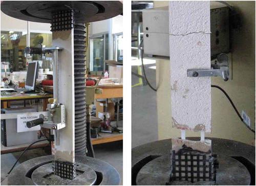
Figure 2. View of the loading set-up for the flexural test of the reinforced masonry stacks.
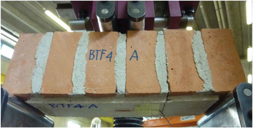
The flexural test was used in substitution of the direct shear test in order to determine the bonding capacity of the FRM to the bricks. In none of the experiments the mortar detached from the masonry prism, although no fastener was applied to the FRM layer. The failure occurred in any case by tensile failure of the fibre mesh.
4. Execution of the diagonal compression tests
A total of 14 diagonal compression tests were carried out according to the ASTM E 519–15 standard on square walls of side L = 1160 mm and thickness t = 118 mm, with different combinations of mortars and reinforcement meshes. In particular, following the combinations of mortar and reinforcement selected by the producer after the tensile testing of the FRM plates, the tests concerned:
Three reference panels without strengthening coatings, 118 mm thickness, running bond texture,
Three panels as the reference but with BTF coatings of 15 mm thickness and GA reinforcement,
Three panels as the reference but with BTC coatings of 12 mm thickness and GA reinforcement,
Three panels as the reference but with BTG coatings of 30 mm thickness and GB reinforcement,
Two panels as the reference but with BTC coatings of 13 mm thickness and SS strip arrangements along sides or diagonals.
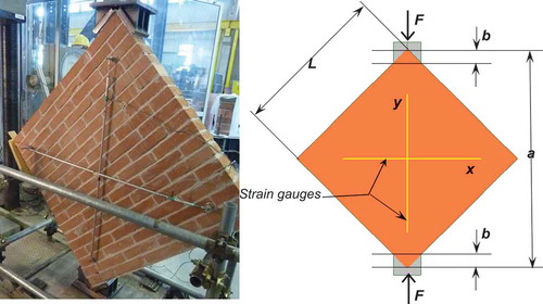
The diagonal compression tests were carried out according to the scheme of . Each panel encompasses 18 rows of bricks and 17 mortar courses. During the tests, the vertical displacement and the strain on the two major diagonals were recorded. The toe depth b on the loaded corners is approximately 100 mm wide.
Figure 3. View of the diagonal test set-up.
The FRM reinforced panels are simply obtained by executing two reinforced mortar layers on the faces of each wall. The two coatings are connected through the masonry thickness by four fibre stringers. The specimens have been set up by standard workers.
The results of the diagonal tests are reported in . Flim is the maximum experimental jack force, εx and εy are the strains recorded by the strain gauges at the peak load, txy, γ and G are respectively average shear stress, distortion and modulus computed according to the RILEM recommendations (Citation1991).
Table 3. Results of the diagonal tests of the 14 experimental walls.
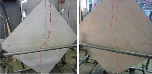
In two characteristic failure patterns are shown. As is evident in the photos, the panels failed with the progressive formation of several tensile vertical micro-cracks in the central zone, ending with a skew-symmetric failure mechanism separating the panel in two parts, from one side of the upper loading plate, to the other side of lower loading plate.
Figure 4. View of the BTC-A and BTG-B panels after the tests.
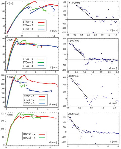
In are presented the diagrams of the vertical load F — vertical shortening δ curves of the various groups. In order to obtain the relevant values of the load–displacement paths, the experimental curves were analysed. In particular, the derivative of the path was extracted and the fit with a piecewise linear representation was obtained. By this way, the peak load, the elastic stiffness, the peak shortening and the post peak softening were evaluated.
Figure 5. Load–displacement curves and derivatives of the tested panels reinforced with G-FRP meshes and steel strips.
5. Interpretation of the observed behaviour
There are many guidelines and studies dealing with the mechanics of the diagonal tests. Among the others, the Documents ASTM E 519 (Citation2015) and the RILEM TC 76 (Citation1991) are two documents that present a complete treatment of the diagonal test results. It is however to point out that masonry is in itself a composite material, and therefore the use of Finite Element Models (FEM), can help in understanding the real strain and stress distributions, as presented in Brignola et al. (Citation2009).
Although RILEM and ASTM formulas look very similar, it is to cite that they give very different values and in some cases they do not agree with the results of FEM analyses. The most diverging quantity is the shear stress value, which in turn leads to a somewhat different shear modulus.
5.1. Interpretation of the diagonal test
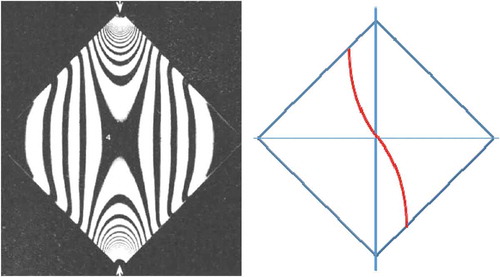
The mechanics of a square plate compressed along a diagonal has always attracted attention. Considering the elastic stress distribution of a homogeneous panel, simply by observing a photo-elastic model (, Broniewska and Mitra Citation1953), the more stressed section is easily detected.
Figure 6. View of the photo-elastic analysis of the diagonal test and skew-symmetric collapse line.
The FEM analysis of the diagonal test can help in interpreting the stress distribution inside the panel. It is however to consider that the masonry is not a homogenous solid, and therefore the deviation of a homogenized material from a masonry bi-material solid is to be assessed.
In the following and two elastic models are presented. They discretize the tested unreinforced panels as a homogeneous macro-model and a micro-model with a real texture and perfect adhesion between mortar and bricks. The comparison shows that the stress patterns are quite similar and allow considering the masonry as a homogeneous equivalent material in the elastic range. In the prepared models, the moduli of brick, mortar and masonry have been set to 6,000 MPa, 2,500 MPa and 4,000 MPa, respectively, according to the series composition formula (Marastoni et al. Citation2016). The thicknesses of brick and mortar courses were set to 50 and 10 mm in agreement with the experimental geometry. In the relevant quantities are compared for a reference load of 100 kN and linear elastic response. In particular the peak and average values of the principal tensile stress σI and tangential stress τxy are listed, as well as the computed shear modulus.
Figure 7. FEM of the homogeneous and composite panels under diagonal loading.
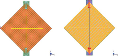
Figure 8. Shear stress distribution under a 100 kN loading of the homogeneous and composite panels.
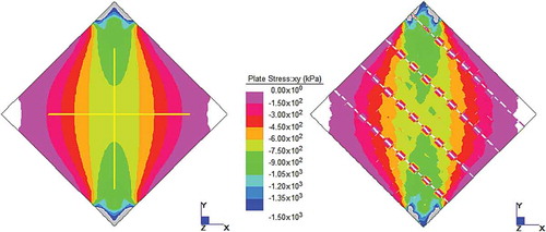
Table 4. Comparison of the results on the centre of FEM models with guidelines (F = 100 kN).
The difference between the two hypotheses is more easily detected by watching at the stress diagrams along the vertical diagonal as in and . It is evident that the mortar courses do introduce only sharp but small local deviations from the distributions of stresses present in the equivalent homogeneous macro-model. Therefore, the use of an average stress value (as in the standards) is allowed.
Figure 9. Distribution of the tensile stresses in the vertical diagonal at 100 kN loading.
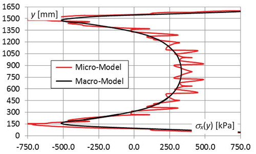
Figure 10. Distribution of the shear stresses in the vertical diagonal of the wall at 100 kN loading.
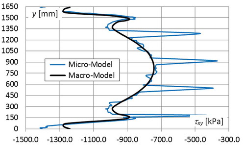
The failure of the panel is in any case occurring by breaking of the symmetry, as in and . Therefore, it is possible to simplify the yield line of obtaining so the Mohr–Coulomb limit equilibrium model of the cracked panel as in .
Figure 11. Limit equilibrium of the internal stresses on the yield line.
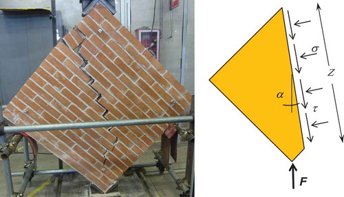
In a compressed section of a material with compressive strength fc and tensile strength ft the maximum shear stress at failure holds:
where fvk0 is the shear strength with null compression stress, defined with the formula:
In (4) c is the cohesion and ø is the friction angle of the Coulomb material considered.
Since both σ and τ are expressed as a function of the load resultant F, the material plastic limit equation (3) allows calculating the limit force Fult.
By setting τ and σ as a function of force F, angle α and length Z of the section, the following equation is obtained:
Since α is lower than 10°, the second term holds 1.0 with a second-order approximation. Therefore, the limit force resisted by the panel is easily computed as a function of fvk0 and the crack geometry. This formula looks very similar to the RILEM one.
5.2. Effect of the FRM coating
FRM layers are materials that link two components in order to balance the behaviour in compression and in tension. The response enhancement is possible only if the tensile capacity of the fibre mesh is overpassing the tensile strength of the mortar:
where fftu is the tensile strength of the mesh wire, fmtk is the characteristic tensile strength of the mortar, tm is the thickness of each reinforced layer, and sf is the grid spacing of the mesh.
If warp and weft possess different capacities, a combination formula must be used in defining the strength at a given inclination over the grid. By considering an orthotropic material several relationships are possible (Liu Citation2001). In the case of failure near to the diagonal of the panel and assuming the simpler Hankinson formula, the average tensile capacity of the fibre mesh is:
where Ntx and Nty are the mesh tensile strengths in x and y directions, θ can be set to π/4 and n is between 2 and 2.5.
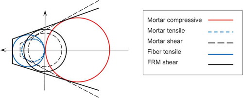
If the tensile strength of the reinforcement fulfils the inequality (7), it can be considered as a sort of “equivalent tensile capacity” fmt,R of the mortar containing it. Thus, the Mohr–Coulomb parameters can be modified according to this equivalent strength, and the new shear strength fvk0,R of the reinforced mortar is easily computed from Eq. 4, simply by properly substituting the tensile strength:
The model for the equivalent strength calculation is presented in .
Figure 12. Mohr–Coulomb representation of the FRM constitutive relationship.
5.3. Calculation of strength and modulus of FRM reinforced panels
As presented in , the ASTM values are in consistent error with the FEM calculation. The RILEM values instead give results in excess of the numerical ones but with a better agreement. By assuming a sufficient ductility of the masonry coated with FRM, the interpretation of the observed panel behaviour is possible with reference to a very simple scheme; in particular, the stiffness of a panel with base L and height H can be determined by summing up the stiffness of the composing layers, by using the formula:
The shear strength of the panel can be obtained in turn by summing up the shear capacity of the bundled layers:
The values obtained through the simple accumulation of the layer’s properties as a parallel system, allow computing the theoretical modulus, stiffness and strength of the tested walls, starting from the mechanical data of the masonry and the data of the FRM coatings applied on it.
In the following and the data of the experiments are interpreted on the basis of the proposed Equations (9), (10) and (11). The analysis of the unreinforced panels is carried out by considering the adhesion capacity of bricks and mortar. The average elastic modulus of the masonry panels is compared with the theoretical one Ewall,th derived from the material properties. The experimental average shear strength of the coated walls fw,ex is compared with the value obtained by the composition formula (11) :
Table 5. Comparison of the experimental and theoretical average wall moduli.
Table 6. Comparison of the experimental and theoretical average shear strength.
6. Verification of the proposed FRM constitutive relation
The proposed theory of FRM shear resistance based on the modified Mohr-Coulomb limit curve is verified against a very large experimental set of data presented by Gattesco, Boem, and Dudine (Citation2015), and Gattesco and Boem (Citation2015). The experimental campaign included brick, cobble stone and rubble stone walls reinforced with different mesh types. Thus, it gives a wide and strong test of the predictive ability of the proposed theory. and report the experimental values and the predicted collapse forces computed from the FRM equivalent shear strength. The observed agreement is very good.
Table 7. Tensile equivalent properties of the mesh according to Eq. 8.
Table 8. Predicted values of the Gattesco, Boem and Dudine (Citation2015) experiments.
It is to mention that even Gattesco and Boem (Citation2015) presented theoretical evaluations that matched very well with the observed behaviour. Their predictions however do include an interpolated efficiency factor extracted from the experimental tests themselves. The present theory on the contrary is able to predict a wide set of situations and results without any empirical modification of the theoretical setup.
For what concerns the data of , the fibre strength evaluated with Eq. 8 for the two fibre sizes S and D are reported in . It is however to point out that in Gattesco, Boem, and Dudine (Citation2015), similar wires at different spacing present non coherent tensile strengths, probably due to a different machining of the meshes. The data of are computed with properties for the S and D wires very similar to the previous one.
Table 9. Predicted values of the Gattesco and Boem (Citation2015) experiments.
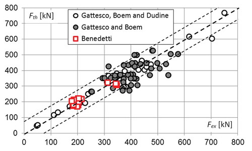
In both and the experimental peak force Fex is compared with the theoretical one Fth obtained by summing up the capacity of the masonry panel Vw with the capacity of the FRM coatings VR. The error is computed as the difference divided by the experimental value.
As is evident from summarizing all the computed results, the proposed theory is precise within a bounded average absolute error of ± 10%, and the largest deviations are on the safe side of the experiments. Moreover, the examined data base encompasses a large range of capacities as well as materials and thicknesses. Finally, the FRM materials are produced by two independent companies with different composition and reinforcement.
Figure 13. Graphical representation of the theoretical versus experimental results of and .
7. Conclusions
The paper presents a wide investigation based on the material characterization and diagonal compression testing of masonry walls strengthened with structural mortar coatings pertaining to the FRM technology. The performed tests allowed for the evaluation of the capacity increase given by those very inexpensive and eco-friendly systems. The shear strength of the masonry walls rose up of more than 100% even with less than 15 mm of strengthening layers on the two wall faces.
The concept of the equivalent shear strength of a mesh-reinforced material has been discussed at the light of the Mohr–Coulomb plasticity criterion. The condition that allows considering FRM plastic in tension has been exploited in terms of relative strength of mortar and reinforcing mesh.
Simple homogenization schemes based on series and parallel element combinations pointed out the effectiveness of the concept based on the fictitious tensile resistance of the reinforced mortar, in predicting the shear behaviour of FRM coatings.
A wide comparison with experimental results discussed in the literature allowed checking the high precision of the proposed evaluation method. The presented experiments encompassed several different combinations of mortars and units, including rubble and cobble stone walls. The presented theory, however, did perform with almost the same precision on all the different experimental setups.
Acknowledgments
The work has been carried out with the support of Saint Gobain PPC Italy under grant DICAM-20160516. The experimental data are property of Saint Gobain and are published according to the contract agreement. The work of the LISG Technicians Roberto Carli, Roberto Bianchi, Mario Marcolongo and Barbara Ravaglia is gratefully acknowledged.
Disclosure statement
No potential conflict of interest was reported by the author.
Additional information
Funding
References
- Adams, H., and E. R. Matthews. 1911. Reinforced concrete construction in theory and practice: An elementary manual for students and others. London, UK: Longmans, Green and Co.
- Arboleda, D., F. G. Carozzi, A. Nanni, and C. Poggi. 2015. Testing procedures for the uniaxial tensile characterization of fabric-reinforced cementitious matrix composites. Journal of Composites for Construction 20 (3):04015063–1:11. doi:10.1061/(ASCE)CC.1943-5614.0000626.
- ASTM - American Society for Testing and Materials. 2015. ASTM E 519–15, standard test method for diagonal tension (shear) in masonry assemblages. West Conshohock, PA: ASTM Standards.
- Babaeidarabad, S., F. De Caso, and A. Nanni. 2014. URM walls strengthened with fabric-reinforced cementitious matrix composite subjected to diagonal compression. Journal of Composites for Construction 18 (2):04013045–1:9. doi:10.1061/(ASCE)CC.1943-5614.0000441.
- Brignola, A., S. Frumento, S. Lagomarsino, and S. Podestà. 2009. Identification of shear parameters of masonry panels through the in-situ diagonal compression test. International Journal of Architectural Heritage 3 (1):52–73. doi:10.1080/15583050802138634.
- Broniewska, C., and M. S. Mitra. 1953. photoelastic method for stress analysis. In Symposium on industrial failure of engineering metals & alloys, 266–75. Jamshedpur, India: National Material Laboratory - CSIR.
- CNR DT 200/2004. 2004. guide for the design and construction of externally bonded FRP systems for strengthening existing structures. Rome, Italy: CNR (National Research Council).
- Donnini, J., and V. Corinaldesi. 2017. Mechanical characterization of different FRCM systems for structural reinforcement. Construction and Building Materials 145:565–75. doi:10.1016/j.conbuildmat.2017.04.051.
- EN 1015-11:2007. 2007. Methods of test for mortar for masonry. Part 11 - Determination of flexural and compressive strength of hardened mortars. Lausanne, SU: CEN.
- EN 1015-12:2002. 2002. Methods of test for mortar for masonry. Part 12 - Determination of adhesive strength of hardened rendering and plastering mortars on substrates. Lausanne, SU: CEN.
- Garofano, A., F. Ceroni, and M. Pecce. 2016. Modelling of the in-plane behaviour of masonry walls strengthened with polymeric grids embedded in cementitious mortar layers. Composites Part B 85:243–58. doi:10.1016/j.compositesb.2015.09.005.
- Gattesco, N., and I. Boem. 2015. Experimental and analytical study to evaluate the effectiveness of an in-plane reinforcement for masonry walls using GFRP meshes. Construction and Building Materials 88:94–104. doi:10.1016/j.conbuildmat.2015.04.014.
- Gattesco, N., and I. Boem. 2017. Characterization tests of GFRM coating as a strengthening technique for masonry buildings. Composite Structures 165:209–22. doi:10.1016/j.compstruct.2017.01.043.
- Gattesco, N., I. Boem, and A. Dudine. 2015. Diagonal compression tests on masonry walls strengthened with a GFRP mesh reinforced mortar coating. Bulletin of Earthquake Engineering 13:1703–26. doi:10.1007/s10518-014-9684-z.
- ICOMOS. 1965. International charter for the conservation and restoration of monuments and sites. 2nd International Congress of Architects and Technicians of Historic Monuments, Venice, 1964.
- Jabarov, M., M. V. Kozharinov, and A. A. Lunyov 1980. Strengthening of damaged masonry by reinforced mortar layers. Proceedings of the WCEE 7, Istanbul, Turkey, Vol. IV. pp.73–80.
- Kouris, L. A., and T. C. Triantafillou. 2019. Design methods for strengthening masonry buildings using textile-reinforced mortar. Journal of Composites for Construction 23 (1):04018070–1:12. doi:10.1061/(ASCE)CC.1943-5614.0000906.
- Liu, Y. J. 2001. Strength criteria for orthotropic materials. Proceedings of ICCE-8, Tenerife, Canary Islands, SP, August 5–11.
- Marastoni, D., L. Pelà, A. Benedetti, and P. Roca. 2016. Combining Brazilian tests on masonry cores and double punch tests for the mechanical characterization of historical mortars. Construction and Building Materials 112:112–27. doi:10.1016/j.conbuildmat.2017.09.120.
- Nervi, P. L. 1965. Aesthetics and technology in buildings. US: Harvard University Press.
- Prawel, S. P., A. M. Reinhorn, and S. A. Qazi 1988. Upgrading the seismic resistance of unreinforced masonry using ferrocement coatings. Proceedings of the 8th IB2MAC, Dublin, IR, pp. 785–91.
- RILEM TC 76-LUM. 1991. Diagonal tensile strength tests of small wall specimens. RILEM, recommendations for the testing and use of construction materials, London: E&FN SPON. 488–89.