
 ?Mathematical formulae have been encoded as MathML and are displayed in this HTML version using MathJax in order to improve their display. Uncheck the box to turn MathJax off. This feature requires Javascript. Click on a formula to zoom.
ABSTRACT
Looseness, deformation, and tenon pulled in the mortise-tenon joint constitute the primary causes of failure in traditional Chinese timber structure building. However, the introduction of the joint damper technology and installation of the fan-shaped shear damper at the mortise-tenon joints of traditional wooden structure solves these issues. Herein, we explored the strengthening effect of dovetail mortise-tenon joints with dampers. We designed six dovetail mortise-tenon joint models, three without dampers, and the other three were installed with dampers. Using the low cycle repeated loading test, we examined the hysteretic response, skeleton curve, stiffness degradation curve, and equivalent viscous damping coefficient curves of the six test models. Consequently, we established that the joint damper effectively controls the joint tenon pulled problem and enhances energy dissipation, strength, and rotational stiffness. Besides, the ultimate bearing capacity of the damper models was nearly four-fold that of models without dampers.
1. Introduction
For ages, traditional timber structures have continued to be built all over the world. This is because wood is naturally available and accessible, easy to process, light, durable, and resilient. Notably, in earthquake-prone areas, including Turkey, Portugal, Italy, Greece, Haiti, India, Japan, and China, timber structures continue to be extensively constructed because of their excellent seismic performance (Aktas et al. Citation2014; Langenbach Citation2007; Poletti, Vasconcelos, and Jorge Citation2014; Ruggieri, Tampone, and Zinno Citation2015; Vintzileou et al. Citation2007). These ancient timber structures are categorized into two main classes. The first category comprises ancient buildings based on specific religious, historical, and cultural values, such as churches, palaces, and temples, etc. A significant number of the structures in this category require repair and strengthening because of weak connections between wooden components caused by decay and deformation of wood. The second class constitutes traditional vernacular architecture constructed using traditional carpentry skills. A considerable number of structures in the latter category are un-engineered and lack architectural planning, therefore, threatened by earthquakes. Different construction methods of traditional timber structures are applied in different locations. Therefore, significant differences exist in their mechanical behavior. For instance, in the Mediterranean region, since the antiquity period, timber has been used to improve the seismic performance of masonry. On the contrary, in Europe, timber is commonly found in floors and roofs of historical architectures(Parisi et al. Citation2015). Based on archaeological findings, the technology of traditional Chinese timber structures involves a longer development process and has a unique architectural style. Regarding this, ancient Chinese timber structures vertically comprise three parts, including, the stylobate, building body, and the roof. The building body and the roof are composed of wooden elements connected using various carpentry joints and erected on the stylobate. For instance, the main hall of Nanchan Temple on Mount Wutai was reconstructed in the Tan dynasty (A.D 782) in Xinzhou city, Shanxi Province, is the oldest (Chen et al. Citation2018).
Carpentry joints play a crucial role in the overall structural response of timber structural systems to applied forces, notably during seismic events. Therefore, numerous scientific studies on the mechanical properties of timber structures, particularly in planning interventions for seismic retrofitting or reinforcement, are centered on joints (Vasconcelos, Loureno, and Poletti Citation2015; Feio et al. Citation2014; Poletti et al. Citation2016; Guan, Kitamori, and Komatsu Citation2008a, Citation2008b). The mortise-tenon joint constitutes the primary carpentry joint in the ancient Chinese buildings and timber structures. Besides, this joint crucially contributes to the maintenance of the overall performance of these structures. Research evidence reveals that most of the structural damages in timber buildings connected using the mortise-tenon joints primarily arise from looseness, deformation, and tenon pulling (Feio et al. Citation2014). These issues cause the whole structure to tilt or even collapse. Therefore, several scientific studies on the factors affecting the overall safety of these structures, including the mechanical properties and working mechanism of the mortise-tenon joints have been conducted (Li et al. Citation2015; Huang et al. Citation2018; Ogawa et al. Citation2016; Xie et al. Citation2018a). Notably, there is increasing research attention on the strengthening of the mortise-tenon joints.
Reinforcement of carpentry joints initially emerged from the need to repair and protect ancient buildings. Regarding this, initial research mainly focused on the effects of traditional reinforcement methods on the mechanical properties of mortise-tenon joints. For instance, (Xie et al. Citation2008) used carbon fiber reinforced polymer (CFRP) sheet and flat steel to strengthen the mortise-tenon joints in the single-story structure and one-bay timber frames. This reinforcement renders good seismic performance to the reinforced timber frames through low-cyclic reversed loading tests. Moreover, (Xu and Qiu Citation2010) selected glued-in bolts and CFRP to strengthen the mortise-tenon joints; and compared with the unreinforced joints to analyze the behaviors of the timber frames of the reinforced joints. A shaking table test analysis on a model of an ancient timber structure palace strengthened using CFRP sheets on its damaged swallow-tailed mortise-tenon joints revealed that the timber frame still had excellent energy dissipation and shock absorption capacity after the joints were strengthened (Xue et al. Citation2012). Additionally, Zhou and Yan (Citation2015)carried out low cyclic reversed loading tests on mortise-tenon joints retrofitted either with an iron hook, CFRP sheets, or steel components to compare the seismic performance of ancient Chinese timber structures strengthened on mortise-tenon joints by different methods, and then suggested the application range of different retrofitting methods. These conventional methods are primarily used to strengthen the mortise-tenon joints of traditional wood structures.
With the development of the damper-damping device with an excellent shock absorption effect, increasing research has focused on the use of the damper in carpentry joints as a method to enhance and improve the seismic behaviors of traditional timber structures. For example, (Lu et al. Citation2014) proposed a strengthening method for mortise-tenon joints by curved steel dampers, and then conducted low-cycle reversed loading tests on five 1/1.67 scaled reinforced wooden frame models to study the structure behaviors. They found that the strength and stiffness of strengthened frames were mostly provided by curved steel dampers. A comparison of the effect of flat steel and damper reinforcement in the straight type of mortise-tenon joints in the Yellow Emperor Temple in Qingcheng Mountain damaged in the Wenchuan earthquake indicated that the seismic performance of the structure was significantly improved by the two strengthening measures, furthermore, the damper strengthening could significantly weaken the seismic responses of the structure without increasing joint stiffness and has the effects of energy dissipation and preventing pulling-out-tenon (Pan et al. Citation2014). The use of friction-type dampers in the reinforcement of the straight mortise-tenon joint of ancient timber structures revealed that the damper reinforcement could provide additional damping of the structure, which helped the joints dissipate seismic energy, and this new damper was applied in engineering practice (Tan Citation2015). A comparison of the cyclic behaviors of low-cyclic reversed loading tests on four 1/3.52 scaled joint models reinforced with shape memory alloy (SMA) wires resulting in moment-rotation hysteresis curves with conventional reinforced joints indicated that the strength, stiffness, and energy dissipation capacity of the mortise-tenon joints strengthened with SMA were improved markedly (Xie et al. Citation2018b). Moreover, a new friction damper was proposed for improving the cyclic response of mortise-tenon joints and the experimental results indicated that the smaller amount of tenon pullout, larger bearing capacity and initial stiffness, and higher energy dissipation capacity simultaneously were exhibited in the strengthened joints (Xue et al. Citation2021).
We developed a new fan-shaped shear damper consisting of steel plates and viscoelastic rubbers and installed it on the wooden dovetail mortise-tenon joint. In the previous study, we carried out a series of experiments on the rotational performance of different tree species joints and different tightness joints strengthened by the dampers (Gao et al. Citation2016; Nie, Tao, and Gao Citation2021). In this paper, we designed three unreinforced dovetail joint models and three other strengthened models and then used low-cyclic reversed loading tests to compare their seismic behaviors.
2. Experimental work
2.1. Test design and model construction
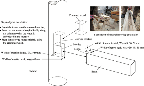
Based on the practices of the traditional Chuandou timber frame in southwestern China, we used Canadian hemlock wood, which is easy to purchase on the market, to design six mortise-tenon joint specimen models. These included three unreinforced dovetail joint models with no damper installed at mortise-tenon joints, and three reinforced dovetail joint models with dampers at the joints. These joint specimen models consisted of a circular column (170 mm diameter, and 1200 mm height) and a rectangular beam (140 mm × 175 mm cross-section, and 1200 mm length). The magnitude of the tightness of these models was fabricated in three ranks (tight, moderate, and loose). The size of the mortise was uniform, and the tightness of the joint model is controlled by changing the size of the tenon (specifically by changing the width of tenon frontal and tenon neck), as illustrated in . The joint models were improved to simulate real stress on the dovetail tenon in the column. Specifically, the upper reserved mortise was installed with a rectangular crammed wood made from the same material and the degrees of tightness. After that, self-tapping screws were used to fix the crammed wood and the column firmly to ensure that the tenon is constrained vertically. The sizes of specimen models are shown in . As shown in , specimens with three degrees of tightness, loose, moderate, and tight, were fabricated separately to consider the influence of different degrees of tightness of the joint on the reinforcement effect of the damper. And the analysis results will be presented in a later article. We also tested the material properties of this batch of wood, and the results are presented in .
Table 1. Details of specimens.
Table 2. Material properties of Canadian hemlock.
Figure 1. Schematic diagram of dovetail mortise-tenon joint model.
2.2. Test performance of our damper
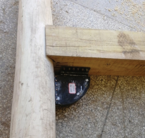
Our new damper consists of two “L” shaped steel plates with a thickness of 5 mm, the long side of the steel plate is cut into a fan shape, the two steel plates are filled with viscoelastic rubber (butyl rubber), and then connect the steel plates firmly with viscoelastic rubber through a high-temperature vulcanization process, as illustrated in . The material properties of damper are listed in . The damper is fixed on the column-beam joint of the timber structure, by using flat end pointed tail bolts with a length of 30 mm and a diameter of 4 mm, as shown in .
Table 3. Material properties of damper.
Figure 2. Damper construction.
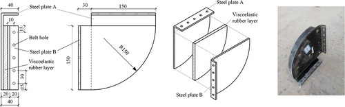
Figure 3. Damper stalled on the column-beam joint.
The three damper specimens were separately subjected to low-cyclic repeated loading tests to understand the energy dissipation mechanism and mechanical properties of the damper, before reinforcing the dovetail joint model test. The displacement control method was used in the test and the loading device is shown in .
Figure 4. Damper test setup.
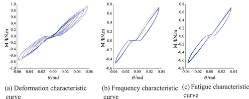
The measured hysteresis curve of deformation characteristic, frequency characteristic, and fatigue characteristic are shown in . The results showed that the pinches-shaped appeared on the hysteresis curves of the three damper specimens, indicating that the degree of fullness is lower than in the spindle-shaped due to the influence of an inevitable slip. However, the damper had a strong plastic deformation capacity and absorbed seismic energy optimally. Our damper is mainly based on the energy consumption of shear deformation, and we named it a shear-type damper for the convenience of recording.
Figure 5. M-θ hysteretic loops of the three damper specimens (a) Deformation characteristic curve (b) Frequency characteristic curve (c) Fatigue characteristic curve.
2.3. Test loading
The test adopted beam end loading, and the vertical-repeated load was applied using the electro-hydraulic servo actuator. The downward push and the upward pull of the actuator constitute positive loading, negative loading, respectively. Two circular steel sleeves were machined and installed on the column foot and column top, respectively, to fix the column foot and the column top and simulate the hinged joint. The steel sleeves were 100 mm deep, and the inner diameter was the same as the diameter of the wooden column. The bottom plate of the column foot sleeve was welded to the steel beam. The steel beam and the reaction floor were connected using the foundation bolt. The design vertical load F of the column top was constantly 10 kN, which was applied to the column using a jack loading device through the column top sleeve. Loading reversals in push and pull direction were symmetric, as shown in .
Figure 6. Wood joint test setup (all dimensions in mm) (a) Test design (b) Overview of the test setup.
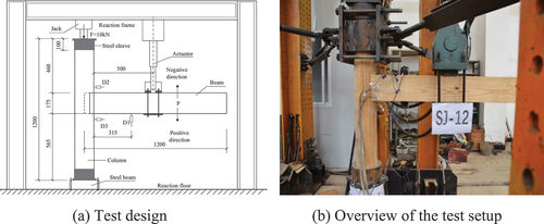
Before applying the reciprocating load, we used a jack to provide a 10 kN vertical load on the column top through the steel sleeve to simulate the stress state of the wooden column in the timber structure. Low-cycle repeated load was applied using an electro-hydraulic servo actuator. We adopted the displacement-controlled loading scheme as shown in . The initial value of the loading displacement was 10 mm; the increment of each stage was 10 mm; the total cycle was 3 times, and the maximum amplitude was 120 mm.
Figure 7. Loading schedule.
Figure 8. The sticking location of the strain gages.
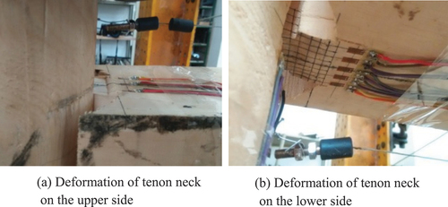
Figure 9. Failure mode of SJ-22 (a) Deformation of tenon neck on the upper side (b) Deformation of tenon neck on the lower side.
2.4. Test measurement
The bending moment as well as the rotational angle acting at the center of the joint and the pullout of the tenon from the mortise were measured in the test. Since the change of the controlled displacement slightly altered the rotation center of the beam, it posed challenges in the measurement of moment and rotation angle. Herein, we adopted the approximate method. The bending moment of the joint was defined by the applied load (P) multiplied by the distance between the center of the actuator and the inner edge of the column (l1 = 500 mm), as shown in ). P was measured using a built-in dynamometer of the electro-hydraulic servo actuator. The bending moment of the joint was expressed as:
We defined the rotational angel using the ratio of the vertical displacement of the beam (Δ) to the distance between the measuring point and the inner edge of the column (l2). A main Linear Variable Differential Transformer (D1) of 750 mm capacity was set under the beam tested to measure the displacement l2. It was located 315 mm away from the inner edge of the column, as shown in ). The rotational angel of the joint was expressed as:
The pullout of the tenon was defined by the length of the tenon drawn out of the mortise, obtained by setting the displacement meters (No. D2 and No. D3) on the upper and lower sides of the root of the beam, as shown in ).
Additionally, the strains of the tenon and mortise were measured during loading to obtain the strain distribution of the joint. The resistance strain gages on the below and both inner sides of the mortise (from No. 1 to No. 9) were used to measure the change of the mortise strain after the tenon extrusion, and the strain gages on the upper and lower of the tenon neck (from No. 10 to No. 19) were used to measure its strain change. The sticking location of the resistance strain gages was shown in .
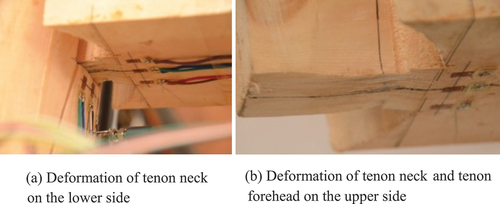
Figure 10. Failure mode of SJ-21 (a) Deformation of tenon neck on the lower side (b) Deformation of tenon neck and tenon forehead on the upper side.
3. Experimental observation
3.1. Unreinforced dovetail joint model
3.1.1. Joint model SJ-22
During the repeated loading process of the joint model SJ-22, the amount of pullout of the tenon was small, about 2 mm for each stage. When loading to the fourth stage, i.e., when the controlled displacement was 40 mm, a slight sound of wood fiber fracture appeared. At the same time, the tenon was pulled out from the mortise. At the end of the fourth stage, the residual pullout of the tenon was approximately 7 mm. In the process of loading to the tenth stage, i.e., when the controlled displacement was 100 mm, the intermittent sound of wooden fiber fracture became louder. At the end of the test, the upper and lower surfaces of the tenon neck had a buckling deformation perpendicular to the wood grain, and the residual pullout of the tenon was about 20 mm, as shown in .
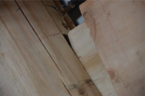
Figure 11. Failure mode of SJ-20.
3.1.2. Joint model SJ-21
There was a wood knurr close to the mortise of the joint model SJ-21. When loading to the third stage, i.e., at a controlled displacement of 30 mm, the sound of wood fiber fracture started appearing, and the pullout of the tenon increased with the loading displacement. In the process of loading to the seventh stage, i.e., at a controlled displacement of 70 mm, the loading displacement increased, the tenon shoulder at the lower part of the tenon was exposed from the mortise, and the residual pullout of the tenon was approximately 15 mm. The breaking sound of wood fiber became louder when it reached the tenth stage of loading, i.e., at a controlled displacement of 100 mm. After completing the loading, the mortise was intact, the residual pullout of the tenon was 31 mm, and the underside of the tenon neck was slightly buckled, as shown in ). The upper side of the tenon neck and tenon forehead was also buckled, as shown in ).
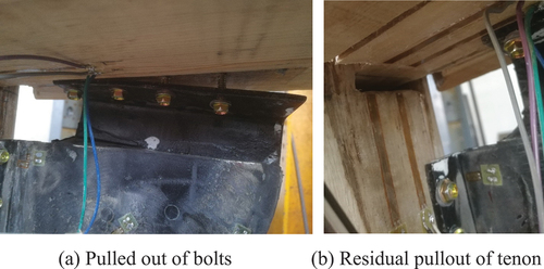
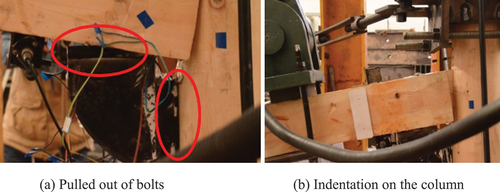
Figure 12. Failure mode of SJ-29 (a) Pulled out of bolts (b) Residual pullout of tenon.
3.1.3. Joint model SJ-20
Defects in the wood knurr in the joint model were observed on the upper and lower sides on the tenon neck and tenon forehead before the test. When loading the second stage (the controlled displacement was 20 mm), the sound of wood fiber fracture began to appear, and an evident pullout of the tenon appeared. Increasing of controlled displacement gradually increased the sound of wood fiber fracture and the pullout of the tenon. When loading to the ninth stage (the controlled displacement was 90 mm), the pullout of the tenon increased suddenly, and the residual pullout of the tenon at the end of the ninth stage was approximately 30 mm. When loading to the tenth stage (the controlled displacement was 100 mm), the pullout of the tenon increased to 50 mm, and the tenon almost fell off from the mortise. Continued loading kept increasing the maximum pullout of the tenon in each stage. However, the tenon reset without falling off due to the fixing effect of the loading position. At the end of the test, the residual pullout of the tenon was about 50 mm, and the joint model lost its bearing capacity, as shown in . Disassembling the mortise-tenon joint after the test, there were many wood chips inside the mortise, and the forehead tenon width was significantly compressed by approximately 2 mm. During the test, there was insignificant deformation on the beam and column.
Figure 13. Failure mode of SJ-38 (a) Pulled out of bolts (b) Indentation on the column.
3.2. Reinforced dovetail joint model
3.2.1. Joint model SJ-29
Joint model SJ-29 was an enhanced version of SJ-22 with basically the same fracture phenomenon of the wood fiber during the loading process. In the first five loading stages, the pullout of the tenon was quickly reset after unloading due to the effect of the damper. However, the damper rubber was misaligned when loading to the sixth stage (the controlled displacement was 60 mm), and about 2 mm pullout of the tenon was not recovered. Increasing the load-controlled displacement increased the amplitude of the dislocation of the damper rubber layer as well as the residual pullout of the tenon. After loading to the eight-stage (the controlled displacement was 80 mm), the first bolt on the outermost side of the damper connecting to the beam was uprooted, and loading to the tenth stage (the controlled displacement was 100 mm), three bolts were pulled out. At the end of the test, four bolts connecting the beam were pulled out and could not reset, as shown in ). The residual pullout of the tenon was approximately 15 mm, as shown in ).
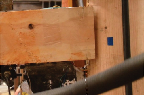
Figure 14. Failure mode of SJ-41.
3.2.2. Joint model SJ-38
The joint model SJ-38 was an enhanced version of SJ-21 with the new type damper, although the wood used to fabricate the model had knurr on the column. There were no defects at the mortise and the tenon. No sound of wood fiber breaking or splitting was heard in the initial stage of loading, and the squeezing sound of the wood was heard in the second stage of loading. At the fourth stage of loading and the controlled displacement was 40, the wood fiber on the tenon emitted a cracking sound and started to break. The two bolts outside the lower part of the beam used to fix the damper began loosening, and the outermost bolt appeared to be pulled out. At the same time, indentations caused by the impact of the beam started to appear on the column. Because the rotational angle and displacement gradually increased during loading, when the maximum displacement reached 60 mm at the sixth stage, the bolts connecting the damper to the column were pulled out by 15 mm. Simultaneously, a residual pullout of the tenon of approximately 10 mm was observed. When the controlled displacement reached 70 mm, a more residual pullout of the tenon of approximately 12 mm was observed. Continued loading, pulled out two bolts connected to the beam when the peak displacement reached 100 mm. Besides, the pullout of the tenon of 20 mm could not be recovered, as shown in ). At the last stage of loading, the peak displacement reached 120 mm, and there was a slight indentation on the column, as shown in ). After loading, the residual pullout of the tenon was about 24 mm, and the beam and column were not damaged.
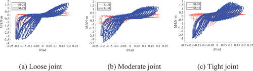
Figure 15. Comparison of hysteresis curves between joint models (a) Loose joint (b) Moderate joint (c) Tight joint.
3.2.3. Joint model SJ-41
The joint model SJ-41 was a compact node. The frictional force that was generated by the lateral squeezing force was more than the restoring force of the joint during the initial installation. Therefore, during the loading process, the unrecoverable residual pullout of tenon started to occur after loading to the third stage (the controlled displacement was 30 mm). At the same time, the rubber layer was distorted, indicating that the damper was involved in the work. The residual pullout of tenon increased with the increase of the load-controlled displacement. When the maximum displacement reached 40 mm at the fourth stage, the bolts connecting the damper to the column were slightly pulled out, and the bolts were reset after unloading. At the end of the test, the pulled-out bolts were reset after unloading, and the residual pullout of the tenon was approximately 15 mm, as shown in . The tests revealed that the joints installed with dampers were restored to a safe state. Therefore, our damper effectively prevents the joint from the pullout of tenon damaging.
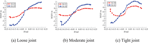
Figure 16. Comparison of the M-θ skeleton curves between the joint models (a) Loose joint (b) Moderate joint (c) Tight joint.
4. Results and discussion
During the test, the strain gages No. 4 to No. 9 arranged inside the mortise were all damaged due to the friction between the tenon and the mortise, so the test data could not be obtained. In addition, most of the other strain gages were unable to obtain reliable data because of the excessive deformation of wood, therefore, there was no strain data analysis in this paper.
4.1. Hysteresis curve
The comparison of the hysteresis curves between the three groups of the reinforced joint and unreinforced joint is shown in .
Figure 17. Comparison of the stiffness degradation curves between joint models (a) Loose joint (b) Moderate joint (c) Tight joint.
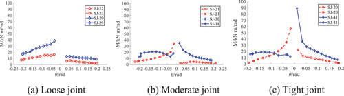
The hysteresis curves obtained from the experiment models had an inverse “Z” shape with pinches. This indicate that the mortise-tenon joints had a significant slippage during the stress process. The pinching effect of the mortise-tenon joint models SJ-22, SJ-21, and SJ-20 without dampers was more than in the SJ-29, SJ-38, and SJ-41 models with dampers, indicating that the damper effectively reduce joint slip. The hysteresis curve showed asymmetry, i.e., the area of the reverse-loaded hysteresis loop was larger than the area of the forward-loaded hysteresis loop, which is determined by the asymmetry structure characteristics of the dovetail joint. The upper part of the tenon was equal to the half straight tenon joint, and the lower part was equal to the dovetail joint with the sleeve shoulder. During negative loading, the lower part of the tenon had a large pressing force with the mortise making it difficult to pull out the tenon. Therefore, this implies there was a large negative stiffness on the hysteresis curve and a higher bearing capacity. Regarding the area of the hysteresis loop, it gradually increased with the increase of the rotational angle. At the same controlled displacement, the area of the negative hysteresis loop was large than the area of the positive loop due to the asymmetry of the dovetail joint. The energy consumption capacity of the dovetail joint was better when loaded upward. From the slope of the unloading section of the hysteresis curve, the slopes of the joint models SJ-29, SJ38, and SJ-41 with dampers on the mortise-tenon joint were smaller than in the joint models of SJ-22, SJ-21, and SJ-20. This indicated that the damper effectively controlled the falling speed of the bearing capacity and enhanced the deformation recovery ability of the joint model. In summary, comparing the hysteresis curves of the joint models, we infer that installing dampers on the mortise-tenon joints can effectively increase the energy consumption of the joint, but whether or not installing a damper at the joint has little effect on the working mechanism of the mortise-tenon joint.
4.2. M-θ skeleton curve
The skeleton curves obtained from the test are shown in .
Figure 18. A diagram showing the calculation of he.
The curves present a comparison of the three groups of the joint models reinforced with dampers and unreinforced. Due to the asymmetric structure of the dovetail joint, the same as the hysteresis curve, the skeleton curve of the dovetail joint models showed a significant difference between the positive and negative loading. To simulate the actual working of the dovetail joint in this study, the upper and lower parts of the tenon had different structure forms. The large head and small neck in the lower part of the tenon caused a strong bite between the mortise and the tenon. Therefore, it showed a high negative bearing capacity on the skeleton curve. Comparing the skeleton curves of the joint models with and without the dampers on the mortise-tenon joints, we observed that in addition to the compact joint model SJ-21 showing strong “S” shaped features, the remaining two models, SJ-22 and SJ-21 without a damper had weak “S” shaped features. However, the joint model M-θ skeleton curves of mortise-tenon joints with dampers had some elasticity. The mortise-tenon joint models with dampers SJ-29, SJ-38, and SJ-41 had about four-fold the ultimate bearing capacity of the models without dampers SJ-22, SJ-21, and SJ-20. The slope of the skeleton curve was also much smaller then the former. This indicates that the damper effectively improves the ultimate bearing capacity of the joint and increases the joint strength.
4.3. Stiffness degradation curve
Stiffness degradation refers to the phenomenon that stiffness decreases with the increase of loading cycles and controlled displacement. Under cyclic loading, joint stiffness is represented by secant stiffness K. The forward secant stiffness and the reverse secant stiffness
of the specimens under repeated loads at all stages are calculated according to EquationEquation (3)
(3)
(3) and (Equation4
(4)
(4) ), respectively. Notations
and
represent the peak forward bending moment of the first cycle of the ith stage load and the rotational angle corresponding to the bending moment. Notations
and
represent the peak reverse bending moment of the first cycle of the ith stage load and the rotational angle corresponding to the bending moment. The forward and reverse stiffness degradation curves of each mortise-tenon joint model calculated by EquationEquation (3)
(3)
(3) and (Equation4
(4)
(4) ) are shown in .
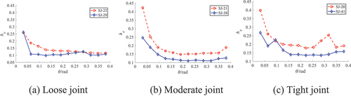
Figure 19. Analysis of equivalent viscous damping coefficient curves in the joint models (a) Loose joint (b) Moderate joint (c) Tight joint.
From the comparison of the stiffness degradation of the joint models, the initial stiffness of the joint models with the damper was greater than that in the joint models without dampers except for the joint models SJ-38 and SJ-41 with dampers under negative loading. However, as the load-controlled displacement increased, the stiffness of the joint models showed a consistent trend, i.e., the later stiffness of the joint models with the damper was greater than that in the joint models without dampers. The above phenomenon indicates that the stiffness of the joint model increases after the damper is installed. At the same time, except for the joint models SJ-38 and SJ-41, the stiffness of the other joint models was generally less than that in the negative loads because of the asymmetric structure of the dovetail joint. By comparing the stiffness degradation curves of the joint models, we established that the minimum stiffness value of the joint models without dampers was close to zero as the load-controlled displacement increased. This indicates that the bearing capacity of joint models without dampers is almost lost after loading. However, the joint models with dampers had a large residual stiffness at the end of loading. This implies that the installation of the dampers enhances the stiffness of the joint model and ensures the safety redundancy of the joints.
4.4. Energy dissipation capacity
In the low-cycle repeated loading test, the mortise-tenon joint absorbed energy when loaded and released energy when unloaded. However, the energy absorbed and released by the joint during a cyclic loading process was not equal. The difference is attributed to the energy consumed by the structure or component in a cycle. It was relatively intuitive to calculate the area enclosed by the hysteresis loop to analyze quantitatively the energy dissipation capacity of the mortise-tenon joints of the timber structures. In this study, the equivalent viscosity was used to quantitatively evaluate the difference between the energy absorbed when the joint is loaded and the energy released when it is unloaded. The equivalent viscous damping coefficient he was expressed as follow:
In EquationEquation (5)(5)
(5) , SAFBE is the area of the hysteresis loop, which is the shaded area shown in .
is the sum of the areas of triangle CEO and triangle EDF.
The energy dissipation capacity of the mortise-tenon joint was analyzed by comparing the change of the equivalent viscous damping coefficient he with the rotational angle as shown in . It can be seen that the equivalent viscous coefficients he of the mortise-tenon joint models SJ29, SJ-38, and SJ-41 with dampers are smaller than those of joint models SJ-22, SJ-21, and SJ-20 without dampers, except for individual points. In particular, for the joint models SJ-21 and SJ-38, the two viscous damping coefficient curves show an obvious regularity of almost parallel changes. In addition, together with , we note that the mortise-tenon joint models SJ-29, SJ-38, and SJ-41 with dampers are larger in the area of the hysteresis loops than the models SJ-22, SJ-21, and SJ-20 without dampers, indicating that the overall energy consumption of the joint models with dampers exceeds that of the joint models without dampers. However, the capacity of energy consumption of the former models is weaker than the latter. Because this fan-shaped damper consumes energy mainly through shear deformation, the viscous damping energy consumption of the joint model is reduced although installing the damper on the mortise-tenon joint increases the stiffness and strength of the joint. Besides, the results shown in indicate that regardless of whether the joint model is equipped with a damper or not, the equivalent viscous damping coefficient he decreases as the rotational angle θ increases during most previous stages of the tests. This is because the joint damping is mainly provided by wood embedding and friction when the rotation angle is small, therefore, the equivalent viscous damping coefficient decreases with the increase of the rotation angle. In the later stages of the tests, the tenon has been mostly pulled out from the mortise, and the joint damping is provided by the damper, so the equivalent viscous damping coefficient increases with the increase of the rotation angle.
5. Conclusions
A new type of fan-shaped damper that strengthens the mortise-tenon joint of Chinese traditional timber structures is presented here. Three reinforced and unreinforced joint specimens were fabricated and low-cycle repeated load tests were carried out. The hysteresis behavior, stiffness degradation and energy dissipation capacity of the joint models under various loading stages were studied using a comparative method. From the experimental results obtained, the following conclusions can be made.
(1) The final residual pullout of the tenon for loose, moderate, and tight joint models without and with dampers are 20 mm/15 mm, 31 mm/24 mm, and 50 mm/15 mm, respectively. Installing fan-shaped damper on the mortise-tenon joint models can reduce the final residual pullout of the tenon by 22.5%–70%, effectively controlling the damages caused by pullout of the tenon.
(2) The hysteresis loop area of the joint model with damper is about 2–3 times larger than that of the joint model without damper, and the hysteresis curve becomes fuller and smoother after installing the dampers on the joint model. Moreover, the joint model with dampers exhibits better recovery ability during the unloading process.
(3) The installation of the damper enhances the strength and stiffness of the joint model. The ultimate bearing capacity of the joint model with damper is about 4 times higher than that of the joint model without damper.
(4) The energy consumption of the fan-shaped damper mainly comes from the shear deformation of the rubber layer, which decreases its energy dissipation capacity of viscous damping. The viscous damper coefficient of the joint model with damper is smaller than that of the joint model without damper.
(5) This study mainly provides qualitative results, the performance of the fan-shaped shear damper and its contribution to the mortise-tenon joint of timber structure should be further quantified.
Acknowledgments
The authors gratefully acknowledge the financial support of the National Natural Science Foundation of China (Grant No. 51168025 and 51868032), Yunnan Provincial Department of Education Fund Project (Grant No. 2019J0194 and 2021J0160). The test was conducted in the Research Center of Seismic Engineering Technology, Kunming University of Science and Technology, which is gratefully acknowledged.
Disclosure statement
No potential conflict of interest was reported by the author(s).
Additional information
Funding
References
- Aktas, Y. D., A. Turer, U. Akyuz, B. Erdil, and N. S. Guchan. 2014. Seismic resistance evaluation of traditional ottoman timber-frame himis houses: Frame loadings and material tests. Earthquake Spectra 30 (4): pp. 1711–32. doi:10.1193/011412EQS011M.
- Chen, J. Y., T. Y. Li, Q. S. Yang, X. W. Shi, and Y. X. Zhao. 2018. Degradation laws of hysteretic behaviour for historical timber buildings based on pseudo-static tests. Engineering Structures 156: pp. 480–89. doi:10.1016/j.engstruct.2017.11.054.
- Feio, A. O., P. B. Lourenco, and J. S. Machado. 2014. Testing and modeling of a traditional timber mortise and tenon joint. Materials and Structures 47 (1): pp. 213–25. doi:10.1617/s11527-013-0056-y.
- Gao, Y. L., Z. Tao, L. Y. Ye, M. Yang, H. X. Su, and W. Z. Yu. 2016. Shaking table tests of mortise-tenon joints of a traditional Chuan-Dou wood structure attached with viscoelastic dampers. China Civil Engineering Journal 49 (2): pp. 59–68. doi:10.15951/j.tmgcxb.2016.02.007.
- Guan, Z. W., A. Kitamori, and K. Komatsu. 2008a. Experimental study and finite element modelling of Japanese “Nuki” joints — Part one: Initial stress states subjected to different wedge configurations. Engineering Structures 30 (7): pp. 2032–40. doi:10.1016/j.engstruct.2008.01.003.
- Guan, Z. W., A. Kitamori, and K. Komatsu. 2008b. Experimental study and finite element modelling of Japanese “Nuki” joints — Part two: Racking resistance subjected to different wedge configurations. Engineering Structures 30 (7): pp. 2041–49. doi:10.1016/j.engstruct.2008.01.004.
- Huang, H., Y. T. Wu, Z. Li, Z. W. Su, and Z. X. Chen. 2018. Seismic behavior of Chuan-Dou type timber frames. Engineering Structures 167: pp. 725–39. doi:10.1016/jengstruct.2017.10.072.
- Langenbach, R. 2007. From “opus craticium” to the “Chicago frame”: Earthquake-resistant traditional construction. International Journal of Architectural Heritage 1 (1): pp. 29–59. doi:10.1080/15583050601125998.
- Li, X. W., J. H. Zhao, G. W. Ma, and W. Chen. 2015. Experimental study on the seismic performance of a double-span traditional timber frame. Engineering Structures 98: pp. 141–50. doi:10.1016/j.engstruct.2015.04.031.
- Lu, W. D., W. Sun, J. J. Gu, D. L. Deng, and W. Q. Liu. 2014. Experimental study on seismic performance of timber frames strengthened with curved steel dampers. Journal of Building Structures 35 (11): pp. 151–57. doi:10.14006/j.jzjgxb.2014.18019.
- Nie, Y. W., Z. Tao, and Y. L. Gao. 2021. Experimental study on dovetail mortise-tenon joints with viscoelastic dampers in traditional timber structures. Journal of Building Structures 42 (1): pp. 125–33. doi:10.14006/j.jzjgxb.2019.0077.
- Ogawa, K., Y. Sasaki, and M. Yamasaki. 2016. Theoretical estimation of the mechanical performance of traditional mortise–tenon joint involving a gap. Journal of Wood Science 62 (): pp. 242–50. doi:10.1007/s10086-016-1544-9.
- Pan, Y., C. Wang, L. Tang, L. J. Li, and P. F. Geng. 2014. Comparative research on flat steel and damper strengthening of straight type of tenon-mortise joints. Journal of Southwest Jiaotong University 49 (6): pp. 981–86. doi:10.3969/j.0258-2724.2014.06.008.
- Parisi, M. A., and M. Piazza. 2015. Seismic strengthening and seismic improvement of timber structures. Construction and Building Materials 97: pp. 55–66. doi:10.1016/j.conbuildmat.2015.05.093.
- Poletti, E., G. Vasconcelos, J. M. Branco, and A. M. Koukouviki. 2016. Performance evaluation of traditional timber joints under cyclic loading and their influence on the seismic response of timber frame structures. Construction and Building Materials 127: pp. 321–34. doi:10.1016/j.conbuildmat.2016.09.122.
- Poletti, E., G. Vasconcelos, and M. Jorge. 2014. Full-scale experimental testing of retrofitting techniques in Portuguese “pombalino” traditional timber frame walls. Journal of Earthquake Engineering 18 (4): pp. 553–79. doi:10.1080/13632469.2014.897275.
- Ruggieri, N., G. Tampone, and R. Zinno. 2015. In-plane versus out-of-plane “behavior” of an Italian timber framed system—the borbone constructive system: Historical analysis and experimental evaluation. International Journal of Architectural Heritage 9 (6): pp. 696–711. doi:10.1080/15583058.2015.1041189.
- Tang, L. N. 2015. Study of mechanical model of column base connection and vibration strengthening in ancient timber structures. Master Dissertation, Southwest Jiaotong University, Sichuan, China.
- Vasconcelos, G., P. B. Loureno, and E. Poletti. 2015. An overview on the seismic behaviour of timber frame structures. In Historical earthquake-resistant timber frames in the Mediterranean area, ed. N. Ruggieri, G. Tampone, and R. Zinno, Switzerland: Springer, Cham 119–132 . doi:10.1007/978-3-319-16187-7_10.
- Vintzileou, E., A. Zagkotsis, C. Repapis, and Z. Ch. 2007. Seismic behaviour of the historical structural system of the Island of Lefkada, Greece. Construction & Building Materials 21 (1): pp. 225–36. doi:10.1016/j.conbuildmat.2005.04.002.
- Xie, Q. F., H. T. Zhao, J. Y. Xue, K. Yao, and Y. Sui. 2008. An experimental study on the strengthening of mortise-tenon joints in ancient Chinese wooden buildings. Chian Civil Engineering Journal 41 (1): pp. 28–34. doi:10.15951/j.tmgcxb.2008.01.007.
- Xie, Q. F., L. P. Zhang, S. Li, W. J. Zhou, and L. Wang. 2018a. Cyclic behavior of Chinese ancient wooden frame with mortise–tenon joints: Friction constitutive model and finite element modelling. Journal of Wood Science 64 (): pp. 40–51. doi:10.1007/s10086-017-1669-5.
- Xie, Q. F., L. P. Zhang, W. J. Zhou, L. Wang, and T. G. Zhou. 2018b. Cyclical behavior of timber mortise-tenon joints strengthened with shape memory alloy: Experiments and moment-rotation model. International Journal of Architectural Heritage 13 (8): pp. 1209–22. doi:10.1080/15583058.2018.1501116.
- Xu, M. G., and H. X. Qiu. 2010. Experimental study on seismic behavior of mortise-tenon joints in Chinese ancient timber buildings. Journal of Building Structures 31 (S2): pp. 345–49. doi:10.14006/j.jzjgxb.2010.s2.044.
- Xue, J. Y., C. W. Wu, X. C. Zhang, and Z. D. Qi. 2021. Experimental and numerical study of mortise-tenon joints reinforced with innovative friction damper. Engineering Structures 230 (6): p. 111701. doi:10.1016/j.engstruct2020.111701.
- Xue, J. Y., Y. Sui, H. P. Ge, H. T. Zhao, X. C. Zhang, and F. L. Zhang. 2012. Shaking table test of joints strengthened with CFRP sheet in Chinses ancient timber structure. Journal of Building Structures 33 (8): pp. 143–48. doi:10.14006/j.jzjgxb.2012.08017.
- Zhou, Q., and W. Yan. 2015. Aseismic behaviors of ancient Chinese structures strengthened by different methods. Studies in Conservation 60 (6): pp. 384–92. doi:10.1179/2047058414Y.0000000137.