
ABSTRACT
This article offers a new approach to analysing the medieval vaults of Norwich cathedral cloister, which at first appearance seem to be of a consistent design, yet detailed inspection and analysis reveals this not to be the case. Whilst previous scholars have recognised the presence of inconsistencies, their focus has been on chronology, patronage as well as the iconographic programme of the extraordinary range of sculpted bosses. Our approach is based on accurate digital surveying and analysis methods and comparison with similar data obtained from other sites. This enables us to understand the design of the cloister vaults in plan, including bay proportions and the nuances of the tierceron star arrangement of ribs. We then employ a representation technique termed the ‘middle plan’ to identify and analyse specific design runs and their breaks in a greater level of detail than previously achieved, including analysis of geometric data to explain different processes that were likely used to create the curvatures of individual ribs. In doing so, we have identified methods not previously described, which reveal the inventiveness of medieval masons faced with a series of complex constructional issues and enabling them to achieve a range of visual effects.
1. Introduction
Cloisters, the circulatory passageways linking the communal buildings of monasteries and some secular cathedrals, offer some of the longest sequences of vaulting, usually following a unified design, and also a site for experimentation in vault design (Monckton Citation2006). The 49 bays of stone vaulting in the cloister of Norwich cathedral in England are particularly intriguing: constructed over a period of 133 years by a succession of patrons and master masons, at first glance all the vault bays appear to share the same tierceron star design, yet closer inspection and analysis reveals many subtle variations, which have captured the attention of scholars since the pioneering work of the architectural historian Robert Willis (1800–75). Willis (Citation1842), focused his analysis on a representation which he termed the ‘middle plan’, where the points of intersection between rib curvatures and a horizontal section line at approximately half the height of the vault are joined together to form a two-dimensional shape, with the total height of the vault defined by the distance from the top of the abacus up to the lower edge (intrados) of the ridge ribs ( top centre). This enabled a comparative visual analysis of individual vault bays and their connecting tas-de-charge blocks. A starting point for this article was a paper written for the Seventh International Congress on Construction History (Webb, Hillson, and Buchanan Citation2021), which provided an initial analysis of the vaults in the east walk, based on a laser scan survey of the entire cloister with subsequent digital analysis. This article will extend both Willis’s findings and our initial paper by investigating the vaulted bays in all four walks of the cloister at Norwich, specifically to identify where design changes were made, how these were achieved via different geometrical processes, and to suggest reasons why changes were made. Our aim therefore is not to attempt to add our own timeline to the much-debated chronology of the cloister (although our findings do support some previous sequences over others), but instead to demonstrate the complexities of the different designs in play as well as the transitions required from existing bays to new ones, given the many pauses in the cloister’s construction. We also aim to reveal similarities and differences between the design of the cloister vaults at Norwich and other examples of English medieval vaulting in order to shed light on the range of design techniques used by medieval masters.
Figure 1. (a) Bay 10 mesh model highlighting walls (red), window tracery (green), vault tas-de-charges (dark blue) and vault ribs and webs (light blue), which could all have been constructed separately. At half the height of the vault a red line cuts through the black vault rib intrados lines, with their intersection shown as black dots in isometric (a), elevation (b) and plan (c).
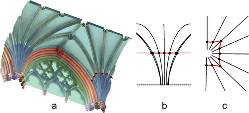
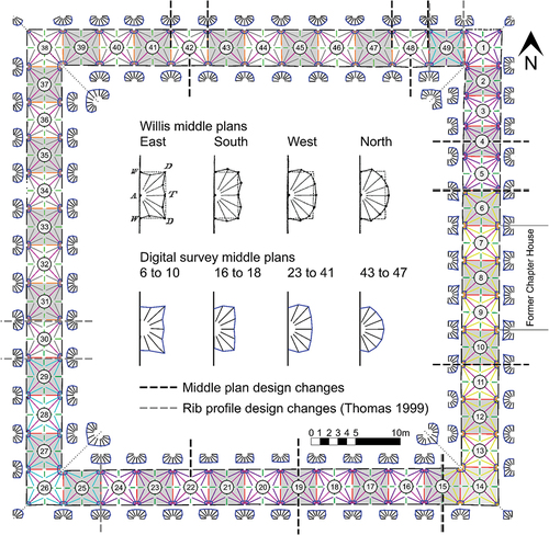
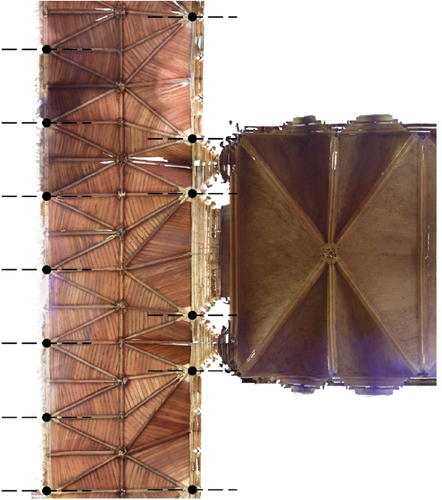
Figure 2. Norwich cloister vault plan with middle plans shown at an increased scale adjacent to bays and changes in middle plan design indicated by dashed black lines across relevant bays. Original middle plans for each run drawn by Willis (Citation1842) are shown top centre, with our equivalent digital survey data shown bottom centre. Ribs are colour coded according to rib profile variations as recorded by Thomas (Citation1999), with changes in rib profile design indicated by dashed grey lines across relevant bays.
2. Norwich cathedral cloister
The foundation stone of Norwich cathedral was laid by Bishop Losinga c.1096 according to the cathedral’s First Register (Saunders Citation1939, 50–51). As a monastic cathedral, the church was adjoined by a cloister and associated buildings, completed by the 1140s (Fernie Citation1996; Heywood Citation1996). In 1272, a dispute between the townspeople and the priory resulted in riots and fires which caused substantial damage to the church and surrounding buildings (Stewart and Willis Citation1875). Whilst the rebuilding of the chapter house and cloister to the current Gothic design has long been associated with this event, Harris (Citation2019) highlights that there are no specific mentions of damage or destruction of the Romanesque cloister in the accounts of the riot given by a monk and a townsperson, respectively. Given the quarter century that passed before building work commenced on the current Gothic design in 1297, along with a lack of evidence of fire damage in the remaining twelfth-century cloister stonework, Harris suggests that the possibly damaged Romanesque cloister was instead demolished slowly and progressively over the 133-year construction period of the Gothic cloister.
After the riots, a replacement chapter house with its entrance on the east cloister walk was completed in 1293 (Woodman Citation1996). The entrance features three arches, facing into the cloister on their west side, suggested by Woodman as the entrance to a vestibule. This would be similar to that approaching the chapter houses at St Werburgh, Chester and Westminster Abbey, both Benedictine monasteries like Norwich. The chronology of the cloister, whilst helped by information in the First Register and a series of financial accounts, is complicated by the duration of construction and apparent use of the same design throughout. Additionally, each of the different architectural components, from window tracery, walls and vaulting elements (), could have been constructed independently and at different stages, thus inviting a range of interpretations from architectural historians. Crucially, this also includes the vaulting, whose tas-de-charge stones, the blocks forming a three-dimensional volume at the lowest part of the vault, must be designed and installed before the individual rib voussoirs departing therefrom. The voussoirs could be constructed at a later period either to the same geometry initiated in the tas-de-charge, or as we shall discuss, to an amended design. The First Register suggests the Gothic cloister was constructed 1297–1430, stating that work began with the three eastern bays 7 to 9 () which formed the entrance to the chapter house, with inscriptions to the west of the entrance ascribing the work to Bishop Ralph Walpole (1289–99) and to the north of the chapter house noting the patronage of Richard Uppshall (who had also built the chapter house). Bishop John Salmon (d.1325) was said to be responsible for the five bays leading towards the church (2 to 6) and the entrance to the church (presumably including bay 1) and towards the entrance to the infirmary (10 to 14) and ‘to the bays in which the towels hung’, identified as the first 10 bays in the south (15 to 24), completed by 1329–30 according to the communar’s rolls (Fernie Citation1993). Binski (Citation2014, 109) and Hawkins (Citation2020, 26) suggest that the use of foliate bosses in bays 7–14 places them earlier than the figurative bosses in bays 1–6. Work then continued slowly and intermittently on the lower components of the bays, completing in c.1394, although authors offer different readings of the sequencing of the various components (Fernie Citation1993; Woodman Citation1996; Sekules Citation2006; Binski Citation2014, Hawkins, Citation2020). All agree the vaulting from bay 25 onwards was a later addition, started in 1411–12 until completion in the north-east corner around 1430. The work is associated with a number of named masters. The vaulting in the east and south ranges may have been undertaken by members of the prolific Ramsey family, also documented as working at St Stephen’s, Westminster, probably at Ely cathedral and at the cathedral of St Paul’s in London, where the now lost cloister was under construction in the 1330s (Harvey Citation1984; Maddison Citation2000; Whittingham Citation1980). Other named masons associated with vaulting include Hervey Lyng (bays 25–26) and James and John Woderuf, who were contracted to vault bays 27–29 in 1420–22. Some carvers responsible for bosses are also named but are hard to associate with particular specimens (Hawkins Citation2020).
3. Methods
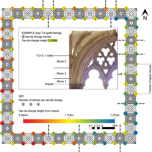
Our first objective was to establish a hypothesis for the two-dimensional bay design in plan, as the starting point before any rib designs can be projected into three dimensions. Our second objective was to produce middle plans for every bay in the cloister, in order to better understand where design changes occurred. This would allow us to expand on the work of Willis (Citation1842), who was able to demonstrate design differences between all four walks of the cloister at Norwich based both on the middle plan and on data tables capturing rib arc geometries, which he used to propose some of the methods involved in their design. Whilst Willis’s findings prove informative to this day, they do not tell the whole story of the vault design in the cloister. It is unclear whether he surveyed every bay of vaulting, and, as our investigation suggests, this appears unlikely given the range of results we have found. A better understanding of design changes was aided by documenting the number of stones forming each tas-de-charge, as well as the height from the impost at which the tas-de-charge becomes individual rib voussoirs (). Our third objective, linked again to Willis's methods, was to capture individual rib arc geometries for every rib in the cloister enabling us to hypothesise their three-dimensional design processes.
Figure 3. Plan of Norwich cloister highlighting the number of stones which complete each tas-de-charge, as well as the height at which individual rib voussoirs depart from the tas-de-charge. These can be compared with bay breaks (black dashed lines) establishing potential design changes from the middle plan study ().
Digital surveying and analysis methods are central to achieving all of these objectives. Our primary tool is terrestrial laser scanning, where a laser pulse is emitted from the scanner and the distance between it and the solid surface it hits is recorded as an x, y, z coordinate in space; an automated process that is repeated hundreds of thousands of times for each scan. In May 2019, we visited Norwich to laser scan the vaults using a Faro Focus 3D X330 at a resolution of 1/4 with a quality of 4×, giving a point spacing of 6.1 mm at a 10 m distance. Raw point clouds were processed enabling the creation and export of mesh models and point clouds; two standard 3D model outputs of laser scan data. Within the 3D models, we identify intrados lines; the innermost curvature of a rib, usually along the lowest exposed edge of the profile. These were traced for every vault rib in the cloister using the software Rhinoceros 3D, in most cases by taking sections through the mesh model, but occasionally by creating a control point curve at mesh vertices. When testing different hypotheses, these are always compared back to the traced intrados lines for verification. Our research relies on the intrados line as the extrados line, the outermost curvature of a rib, at Norwich, as at most English sites surveyed, is usually hidden by infill rubble or brick backing. A study of the webs, the fabric in-between each vault rib, could extend our investigation further but is outside the scope of this article.
The digitally traced intrados lines are viewed in plan to aid our first objective of understanding the two-dimensional bay plan. We also use orthophotos, where point cloud data is viewed orthographically, to cross reference and double check. The intrados lines assist our second objective of creating middle plans, as the intersection between these and a plane at half the height of the vault from impost level to ridge rib intrados in elevation forms the middle plan pattern, which reveals potential design changes across bay runs ().
To aid our third objective, best fit arcs are taken through the traced intrados lines to enable geometric data of radii and arc centre points in relation to the impost level (the point at which a rib departs from the vertical) to be extracted. Similarly, the best fit arcs are extended where necessary to form notional apex heights, which are covered by boss stones in the built vaults. Measurements outlining the geometry of every rib in every bay, including the number of arcs per rib, are added to a data table to initiate analysis of rib designs in three-dimensions.
To further assist with the elements of objective three, we used total station surveying, a laser measuring method that pinpoints individual points in three-dimensional space. Here, we surveyed mortar joints of ribs of particular importance for our analysis of identified bay runs to be discussed in section 6. Viewing the junctions through the total station’s telescopic lens enabled very thin joints, often camouflaged by their similarity to the adjacent stonework in the laser scan data, to be accurately documented (Maira Vidal Citation2017; Wendland Citation2019). Total station was therefore critical in enhancing understanding of some of the more complex methods of arc design.
4. Bay design in plan
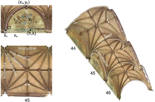
Investigating the two-dimensional design of the bays in plan involves both the bounding dimensions and proportions, as well as the rib patterns. The boundary of each bay is defined using the intrados line of the longitudinal and transverse ribs ().
Figure 4. Mesh model of north bay 45 highlighting rib types in plan and 3D, as well as the annotation system for bay design in elevation including the springing point (O), springing profile length (xs), length in plan or span (xa), apex height (ya), apex (xa,ya), centre (h,k) and radius (r).
4.1. Bounding bay proportions
The Norwich cloister bays are square or near-square in plan (), with notable exceptions in the east walk. Starting at the entrance to the former chapter house, bays 7 to 9 are consistent in their proportions, with an average transverse (east-west) dimension of 4.165 m and an average longitudinal (north-south) dimension of 3.909 m, creating near-square bays. Harris (Citation2019) suggests a perfect square was not possible in many cases based on the decision to reface parts of the original Romanesque fabric into the new Gothic design. These three bays outside the former chapter house complicate the design as they are not central to the overall cloister grid (Fernie Citation1993). Moving southwards in the east walk, the average longitudinal (north-south) dimension of 3.91 m continues for bays 9 to 12, with only longitudinal (north-south) bay 13 being slightly squeezed to a dimension of 3.745 m, where it meets the corner bay 14 in the south-east. However, moving north in the east walk is more problematic, as repeating bays of the same length do not so easily meet north-east corner bay 1. The masons decided to add five bays here, resulting in an extra fourteenth bay to the east when including the corners. To create these five bays, the masons took a transitional approach, with bay 6’s longitudinal dimension of 4.04 m being slightly larger than the original run of 3.91 m, followed by 3.745 m in bay 5, 3.437 m in bay 4, 3.424 m in bay 3 and finally 3.305 m in bay 2. Harris (Citation2019) states that this transitional approach was unlikely to have been required in the previous Romanesque cloister, since the probable design included a closely spaced arcade without separate bays.
A similar manipulation of bay sizes can be found at other sites of medieval vaulting in England, for example, the east-west dimensions of the high vault bays in the nave at Exeter decrease as they approach the existing west front (Webb and Buchanan Citation2019). An alternative solution, or perhaps justification for the transitional approach described for Norwich and Exeter, is offered in the near-contemporary cloister of Lincoln cathedral (c.1290–1300). Here a similar layout to Norwich is found, with an entrance to a pre-existing chapter house vestibule to the eastern edge of the east walk. Unlike Norwich, however, it features a different layout from the grid of the inner tracery to the western edge of the east walk. This results in an awkward solution using the ribs of the timber vaulting to connect the two systems, particularly when viewed in plan (). Although the existing vault was substantially modified by J.L Pearson’s nineteenth-century restoration, earlier plans and the surviving bosses demonstrate that the original plan used a similar solution, with different numbers of ribs on each side of the vault (Alexander Citation2006).
Figure 5. Orthophoto plan of Lincoln cathedral east cloister and chapter house vestibule. The western edge of the cloister walk features a different grid pattern from the eastern edge, with the two systems bridged via the vault design in plan.
4.2. Tierceron star design
The majority of vaults designed for square or rectangular bays rely on proportioning systems that can be drawn using only a ruler and a set of dividers. An example of this is the starcut diagram, as termed by Stewart (Citation2009). Here, a line is drawn from one bay corner to the opposite midpoint then back to the adjacent bay corner to form a chevron. This is repeated for all four sides of the bay, which completes the starcut (). Our preconception was that this simple and consistent design in plan was used to create a tierceron star based on quarters throughout all cloister bays at Norwich; however, overlaying this with our traced laser scan data proved a poor match.
Figure 6. Standard starcut design in plan showing potential bay divisions (a) and hypotheses of vault bay designs for the cloisters at Westminster (1/5, b) Wells (circle starcut, c) and Norwich (2/9, d). Orthophotos overlaid with the hypothesis form the lower row.
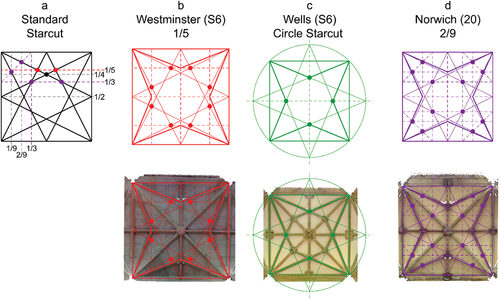
The starcut is a useful geometric device as the intersections of its lines can be used to create different proportions of the bay such as thirds, quarters, fifths (), and even sevenths, ninths and elevenths with additional steps. For the vault design plan of the south and west walks of the cloister at Westminster Abbey (1344–1365), the tierceron star is based on fifths () and we therefore decided to test this system at Norwich; however, it was also a poor match. We next tested the outer circle starcut, a variation of the standard version with chevrons extending beyond the bay boundary (Buchanan, Hillson, and Webb Citation2021), as this was found in the fifteenth-century cloister vaults at Wells Cathedral (). This was also unsatisfactory and for some time our working theory was that the masons aligned the tiercerons to the outer edges of the proposed boss stones at the apexes of the bay’s bounding ribs.
Further testing suggested that tierceron apexes are a very close match at two ninths distance across the bay (). This is a complex fraction compared to other scanned sites in England. Why would the masons at Norwich choose two ninths? One theory relates to an alignment with the boss stone edges as already discussed: these bounding and central bosses are close to one ninth of the width of the bay, suggesting that the bay could have been laid out using a grid of ninths. Our hypothesis for the two-dimensional design of the cloister is therefore square, or near square bays, with a tierceron star design based on a proportion of two ninths ().
Our discussion of the process of designing the vault plan highlights the complexities and nuances in attempting to understand the geometric design principles of medieval vaults; whilst we are confident in our hypothesis, we cannot be entirely certain that these processes were used by the masons in exactly the same way. This is also the case when designing rib curvatures in three-dimensions, which is even more complex than the two-dimensional plan.
5. The middle plan and design changes
Once we were satisfied with the process of designing in plan, we began to consider the design of rib curvatures, first using the middle plan, taken at half the height of the vault. This tends to be close to the point at which vault ribs become individuated voussoirs, emerging from the converged ribs of the tas-de-charge below. In the cloister at Norwich, the average height at the top of the tas-de-charge is 53% of the overall bay height from impost level to the ridge rib intrados, hence working with half the vault height to produce middle plans. This height does vary throughout the Norwich cloister, however, with the minimum being 45% and the maximum being 58% of the vault height. The top of the tas-de-charge as a percentage of the vault height varies at other sites, for example, in bay 13 of the nave vaults at Exeter they sit at 57%, in the east cloister at Wells cathedral they average at exactly 50% and along the western edge of the east cloister at Lincoln they sit at 59% of the vault height.
The middle plan enables comparison of three-dimensional bay designs using a two-dimensional visual analysis of traced intrados lines, from which we are able to categorise bays into different runs on the basis of rib curvature changes (). Middle plans are particularly useful in the study of English late Gothic vaults due to the increased number of ribs these often feature in comparison to simpler vaults such as quadripartite designs. This results in more middle plan edges to compare. Likewise, English Gothic vaults often feature three-dimensional arc designs that have their centres either above, on, or below the impost line, which can greatly affect the pushing forward or backwards of the ribs and consequently the middle plan design (). A lack of these features (for example, some continental vaults which all feature arcs with their centre points on the impost line) may produce less differentiation in middle plans. We can then use rib curvature information to interrogate the three-dimensional design in detail by capturing numeric data such as rib radii (r), arc centre points (h,k), spans (xa), and apex heights (ya), which form the starting point of geometric analysis (Section 6).
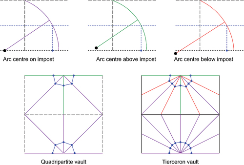
Figure 7. Elevations of three ribs with arc centres on (purple), above (green) or below (red) the impost line. The plans demonstrate middle plans (blue) where all ribs have their arc centres on the impost (lower plan half) compared to ribs with arc centres on, above and below the impost (upper plan half). The more ribs there are, such as in a tierceron vault, the easier the changes are to identify via the middle plan than simpler vaults such as a quadripartite design.
5.1. Willis’s middle plan
Willis (Citation1842) was the first to propose the middle plan as a method of better understanding design changes in vaulting. In relation to Norwich, he discussed the properties of the bays along different cloister walks collectively, based on the middle plan of the central bays of each walk, which we assume therefore are bays 7 to 8 (east walk, no single central bay), bay 20 (south walk), bay 32 (west walk) and bay 44 (north walk) (). For example, Willis’s middle plan of the north walk is nearly semi-circular, from which he identified that most of these ribs were therefore two-centred as opposed to single-centred, with a consistent lower arc radius except for the longitudinal ribs which retire inwards. However, Willis did not identify the extent of the use of two-centred ribs for individual bays in this walk, for instance, he does not discuss potential differences between bay 40, 45, 49 and so on. This offers us an opportunity, more than 180 years later, to compare our comprehensive middle plans to those of Willis, particularly in establishing design breaks or developments between individual bays or runs rather than collective walks. For Section 5.1 and 5.2, the enlarged middle plans in should be consulted alongside the text.
As a first step, we directly compared our results with those in Willis’s diagram (). It is unclear whether Willis based his middle plans on vault ribs springing to the outer or the garth-side walls of the cloister walks. Nonetheless, on both sides of the bay, we see a clear alignment between plans for central bays in the east (bays 7–8), west (either 31–32 or 32–33) and north (either 43–44 or 44–45). Alignment between Willis’s diagram and our data is less clear for the south walk. Bay 20 is central in the south, therefore the tas-de-charge of either 19–20 or 20–21 could be used, both of which feature the same middle plan pattern in our data (). Here, the garth-side walls have a near-rectangular middle plan marking a distinct difference from Willis’s version. The only commonality is that the wall ribs retire inwards slightly. The outer walls are a closer match; however, the transverse rib in our data does not include the distinct retiring inwards of the central dividing transverse rib. Looking further east, the tas-de-charges on both outer and garth-side of 15–16 through to 18–19 represent a clear alignment to Willis’s drawing of a central south bay. It is therefore probable that Willis chose not to use a central tas-de-charge for the south walk which is highly unlikely to have been accidental, given the accuracy of his work. A later set of notes (Stewart and Willis Citation1875) indicates that he did record the middle plans for five bays in the east (6 to 10); however, no mention of multiple bays to the south can be found. Why would Willis decide to demonstrate his theories for the southern walk using a middle plan that is off centre? Perhaps, the inconsistency between outer and garth-side middle plans for 19–20 to 21–22 meant that, given the argument he was proposing, a consistent yet off centre middle plan was more suitable. Similarly, the outer middle plans for 19–20 to 21–22 in the south are consistent with those of the west walk, challenging his theory of distinct middle plans for each walk.
5.2. Design changes
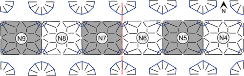
Given that the variation of middle plans in the cloister is not as straightforward as indicated in Willis’s analysis, based mainly on single bays representing entire walks, we looked at the form of the middle plans of all other bays, focussing on those where changes are evident (). These were then compared to previous scholarship to look for correlations and differences. In the east walk, we find two sets of middle plans that are significant given their asymmetry: 5–6 and 10–11 (). The half middle plans facing the centre of the walk, in bay 6 and bay 10, have one design with distinct protruding diagonal ribs as described by Willis to characterise the eastern walk. On the other hand, the half middle plans in bay 5 and 11, that face the corner bays, are more polygonal in their form. We find this asymmetrical type of middle plan at other sites such as the choir aisles at Wells cathedral where the junction between the three eastern and three western bays (N6-N7) features different designs ().
Figure 8. Wells cathedral north choir aisle vault plan with increased scale middle plans. An asymmetrical design is found at N6-N7.
Evidence of asymmetrical middle plans is also found in the outer walls of bays 42 and 48 of the north walk, although these are subtler, yet evidence nonetheless that the masons were creating transitional designs from one bay run to the next. This complicates the suggestion of Fernie (Citation1993), Sekules (Citation2006) and Hawkins (Citation2020) that these tas-de-charges were all built in one campaign. The middle plans indicate a distinct run from bay 23 in the south, through the entire western run and ending in bay 41 in the north, which changes to a new middle plan design in the northern run of bays 43 to 47. Bay 42 is therefore used to transition between these two distinct designs. The relative chronology of the two designs is indeterminate. Likewise, the same scenario occurs in bay 48 (and bay 49), which has the challenge of joining itself to the built fabric of an earlier campaign in the north east corner.
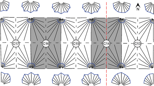
Symmetrical middle plans are the norm in medieval architecture, given the prevalence of one design being repeated from bay to bay. Besides asymmetrical middle plans, also indicates where symmetrical middle plan designs change from one bay to the next, for example, moving from one design to the south of bay 4, to another in the north, or from one middle plan to the east of bay 19, to subtly different designs in the west. In these scenarios, the threshold between the change in design occurs within the bay itself, with the central transverse ridge rib acting as a transition point. On the other hand, a change in design takes place across the bounding transverse ribs in asymmetrical middle plans. The high vaults of the nave at Exeter cathedral (c.1290-c.1340) provide an example of this, as the first bay west of the crossing was built with the same tas-de-charge stones in all four corners (C13), which is reflected in the middle plans of this bay. Moving westwards, the next bay has a different middle plan in the west (C14), suggesting the existing tas-de-charges from the first bay were retained, with the change in design taking place along the transverse (north-south) ridge line of C14 ().
Figure 9. Exeter cathedral nave high vault plan with increased scale middle plans. A design change is clear within bay C14.
At Norwich cathedral cloister, middle plan discrepancies in the corner bays (1, 14, 26 and 38) are less problematic, as these need to adapt to changes in the bay direction as well as entrances to other areas of the cathedral and precinct. It is therefore unlikely that different middle plans for the corner bays represent design changes as such, as they cannot be directly compared to the majority of bays which progress laterally. Nevertheless, observing how the middle plans progress through all four corner bays, it is clear that the design of the half middle plan immediately preceding the corner is the same as that which immediately succeeds it. For example, the rounded half of the middle plan to the south of bay 13 reappears in the eastern half of bay 15, despite the portions of the middle plans internal to bay 14 containing a different design to address the unique constraints of that bay (). This suggests that the medieval masons intended to continue with established designs once corner bays were completed.
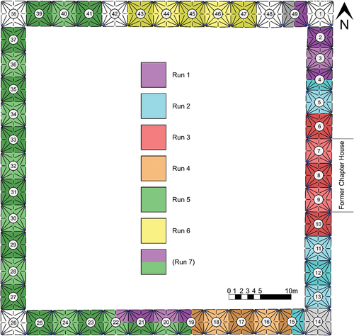
Considering the changes in middle plan evident in , excluding transitional and corner bays, the cloister at Norwich appears to include six distinctly different design runs, or seven if including the southern run of 19–20 to 21–22 which has different middle plans for the outer and garth-side walls ().
Figure 10. Norwich cloister vault plan with colour fills indicating the extent of individual design runs found in our analysis.
The above discussion presents three scenarios faced by medieval masons in addressing design changes along bay runs, which are demonstrated via the east walk (): either a bay boundary design change (, option one and two) or a mid-bay design change (, option three). If we assume that an existing bay is built with a tas-de-charge designed symmetrically between bays, option one would be to alter this on the new side of the bay division, creating an asymmetrical design (, option one). This could be effected by removing stone if the change in design allowed for this, for instance, if arc centre points are raised (), this can create a steeper curvature near the springing point, depending on the geometric properties of that rib. For example, overlaying the existing symmetrical middle plans straddling bays 6–7 with the asymmetrical ones in 5–6 demonstrates a match to the southern side and a subtraction to the diagonal ribs on the northern side. It is therefore possible that the stonework to the tas-de-charges on the north sides of bay 5–6 reworked a design that was already in place, suggesting option one was used (). Our research in the fourteenth-century choir aisles at Wells cathedral also indicates examples of option one, where the design changes between the three south eastern and south western bays the lower tas-de-charge block’s design is altered by removing stone, supported by evidence of the possible remains of a rib profile of the previous design. The upper tas-de-charge block appears to have been partially removed and replaced by cutting the block between the transverse rib and outer tierceron in the side of the new bay, as indicated by a vertical mortar joint where the new partial block has been added (Buchanan, Hillson, and Webb Citation2021, 197–198). In the cloister at Norwich, we have found no evidence of vertical mortar joints indicating the removal and replacement of partial blocks, suggesting the only way in which option one was implemented was when existing stonework could be removed to form a new altered design.
Figure 11. Photographs of vault tas-de-charges adjoining the cloister garth in the east walk at Norwich cathedral, bays 3 to 7.
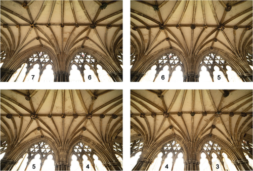
Figure 12. Orthophoto elevation montages highlighting three scenarios faced by medieval masons in addressing design changes along bay runs.
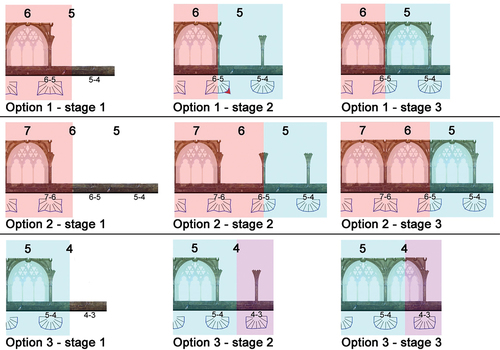
In scenarios where ribs feature new designs that push further forwards into the bay than the existing design, material would need to be added rather than subtracted. This makes option one difficult, unless a change were made via the removal and replacement of an upper tas-de-charge block as seen at Wells. Option two is therefore to inherit the existing design and complete an extra bay of the previous geometry by creating an asymmetrical tas-de-charge design at the next transverse bay boundary, featuring the previous design to one side and the new one to the other (, option two). This seems less preferable, however, as such a solution is only possible over two bays rather than one. Evidence for option two is vague in the cloister at Norwich; perhaps, this occurred in the northern run where incremental change between middle plans across more than one bay is evident (41 to 43 and 48 to 49), or in bays 6 and 10 which we will discuss. Another solution when dealing with additions would be to make a mid-bay change as described for option three. This is perhaps the simplest as it absorbs the change in design within a single bay, as long as the ribs from either side of the bay meet at the same transverse ridge rib height dividing them (, option three). This results in symmetrical middle plans for both rib sets within each side of the bay, for example 4–5 to 3–4.
The above middle plan data revealing potential runs via design changes can be compared with chronologies suggested by Fernie (Citation1993), Woodman (Citation1996), Sekules (Citation2006), Binski (Citation2014) and Hawkins (Citation2020). Additional cross referencing is provided by observations of impost to tas-de-charge heights and the number of stones forming each tas-de-charge block (, as well as the vault rib profile survey of Thomas (Citation1999). Here, changes in rib profile designs are indicated by different colours in with potential breaks based on this indicated as grey dashed lines. Willis downplayed variations in rib profiles of the cloister as they tend to adhere to an original design throughout (Stewart and Willis Citation1875, 159). However, Thomas’s recording of subtle differences shows three variations of transverse ribs, two types of ridge rib, four tierceron rib profiles and a single diagonal rib profile. In many cases, these profile changes align with our studies of middle plans (), for example, there is a clear change of tierceron rib profile and middle plan between bays 5 and 6. A change in rib curvatures at this point was also identified by Fernie (Citation1993); however he, Woodman (Citation1996) and Binski (Citation2014) use the First Register documentation to argue for a break between bays 6 and 7. Our data suggests that the vault of bay 6 might have been part of the earliest run, especially as the tas-de-charge to the north of 5–6 could have been amended as described in option one above ( option one), or perhaps demonstrations that option two was used to mediate the change in design ( option two, ). Like our data, Fernie (Citation1993) and Woodman (Citation1996) identify changes between bays 10 and 11. Binski (Citation2014) identifies that the vault bosses from bay 7 southwards have foliage decoration in contrast with the figurative sculpture from bay 6 northwards. Given the change in three-dimensionality already mentioned, this suggests that the bosses were carved independently of the voussoirs.
Our findings and those of Thomas (Citation1999) also complicate previous research into design changes in the north east corner, where Fernie (Citation1993) and Sekules (Citation2006) suggest a break in the vaulting at 49–1, whereas the rib profiles and middle plans suggest that the change was made gradually, starting from bay 48 (), as argued by Woodman (Citation1996). The most likely scenario here, given that the early 14th-century tracery and arches of the earlier campaign are evident in the south of bay 49, is that a tas-de-charge was included to the south of 48–49 as part of the initial building campaigns, and a new one added to the north of 48–49 as construction neared completion in the 1420s. This theory is supported by studies of the tas-de-charges themselves, as shown in . To the south of 48–49, the departure height of individual rib voussoirs from the tas-de-charge is noticeably higher than the north of 48–49, further evidence that they may have been part of different sequences.
All previous scholarship identifies a break between bays 14 and 15, which our data supports. Woodman (Citation1996) notes a change between bays 19 and 20, and our data supports a design change in bay 19 as discussed previously, further supported by distinct differences between tas-de-charge to individual voussoir departure heights of outer and garth-side blocks (). Excluding corner bays, the middle plans from bay 23 to 41 are uniform, therefore despite the evidence of a documented change in master mason and rib profiles, the three-dimensional design of the vaults remained consistent (). This single design of run five from bay 23 to 41 does suggest that it was constructed continuously, potentially allowing the same centering and stonecutting tools to be reused. On the other hand, breaks such as that found around bay 41 are evidence that work may have stopped for enough time to require the timber centering and stonecutting templates such as the bevel to be remade, hence one possible reason for a subsequent change in design, for example as seen in run six from bay 43 to 47. Sekules (Citation2006) and Hawkins (Citation2020) argue that the south, west and north garth walls were constructed as one mid-fourteenth century campaign based on the sculpture of the keystones. If this is correct (see below), the tas-de-charge must have been set into the wall later. Our data suggests the end of run five lies somewhere between bays 40 and 42, with Fernie (Citation1993) suggesting a change between 40 and 41, and Woodman (Citation1996) between 41 and 42. This disagreement might be explained by the existence of two identically asymmetrical middle plans to the outer wall for bay 42 (), which has no constructional rationale and suggests a pragmatic response to miscommunication between master and cutting masons. On the other hand, a simpler mid bay transition occurs to the garth-side wall for bay 42. Scan data helps clarify the complexities of transitioning from an existing design to a new one. Our research extends previous knowledge by seeking to understand the geometrical processes used to generate the rib curvatures required by the complex sequencing described above.
6. Rib curvatures
Traced intrados line data, converted to best-fit arcs, enables us to scrutinise the underlying geometry of vault ribs in three dimensions. For each rib, the number of arcs making up its curvature is recorded, followed by statistics for each arc. All of the vault ribs in the cloister at Norwich, except the ridge ribs, notionally begin at the bay corners as defined by the two-dimensional plan. In reality, however, springing points (O) begin a slight distance (xs) in from the bay corner to account for the depth of the tas-de-charge stones that sit on top of respond capitals (). Consequently, for each rib the true span distance (xa) is the springing point (O) to the end of the rib in plan. In the cloister, the starting plan of the ribs is usually a half circle centred on the bay corner, but not always. Therefore, the springing point (O) of each rib can be found at the intersection of each line drawn to create the ribs in plan and the circle used to form the starting plan (). The first three runs situated in the east all have a starting plan that is pushed forwards by approximately 0.035 m, whereas runs four and five predominantly in the south and west walks have starting plans centred exactly on the bay corner. The starting plan of the sixth run in the north walk is pushed backwards by approximately 0.04 m giving less space for the ribs (). It is unclear why these slight adjustments may have taken place, or whether they were simply minor errors during construction. Nonetheless, they are significant as the pushing forwards or backwards of the circle centre point effects the middle plan position above it.
Figure 13. Starting plans based on a circle centred on the bay corner (a), pushed forwards (b) and backwards (c), demonstrating the effect on the springing points (O) and springing profile length (xs) for each rib.
As springing point (O) and span (xa) are predetermined based on the two-dimensional plan, these are therefore always known elements when analysing three-dimensional design methods. The three main statistics recorded to analyse three-dimensional design are the arc radius (r), its centre point (h, k) in relation to the impost at the abacus line of column capitals, as well as its apex height (ya) which is a notional point where rib arcs converge and are usually covered by a boss stone (). The averages of these data types across specific bay runs assist in determining which design methods were likely used, enabling us to look for known and unknown geometry (). Hypotheses are usually based on a bay towards a centre of a run to avoid those which may begin to transition as they near a different run, and averages for the fifth run exclude bays 23 to 25 in the south and 39 to 41 in the north due to the added complexity of changes in direction. Studies of design changes via the middle plan in section 5 have revealed the extent of six design runs, therefore each of these are referenced in the sections below (). The numbering of the runs does not indicate chronological priority, and the rationale for choices is discussed in section 7. The middle plan is used as a moderating device, where both the hypothesised and original representations derived from the traced intrados lines are overlaid and compared (). This is in addition to the actual and hypothesised rib curvatures themselves, which are overlaid and compared as part of the research process. Our analysis indicates that many methods and combinations of geometric design are featured in the vaults of the cloister at Norwich, including both single-centred and two-centred ribs, as well as three-centred arches ().
Figure 14. Rib curvature methods of geometric design for the six established bay runs shown as quarter bay plans. The block background colour represents each bay run as shown in . For ease of comparison, each plan is aligned with the transverse rib running across the page (horizontal
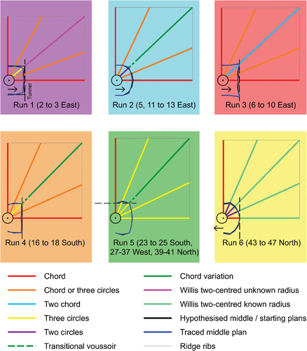
Table 1. Average geometric data in metres for ribs across bay runs in the cloister vaults at Norwich cathedral. ‘Arc/lower arc’ refers to either a single-centred rib (arc) or the lower arc in a two- or three-centred rib (lower arc). Where two- or three-centred ribs occur, their geometry is recorded as ‘upper arc’.
6.1. Single-centred ribs
Many ribs in English medieval vaults are single-centred, and different methods of geometric design offer solutions depending on which of the three main factors are unknown and thus need to be generated, in addition to having already identified the springing point (O) and span (xa) via the two-dimensional design process (Buchanan, Hillson, and Webb Citation2021):
To generate an unknown radius, the ‘chord method’ is used, based on a known apex and arc centre point usually located at impost level.
To generate an unknown arc centre point, the ‘three circles method’ is used, based on a known apex and radius.
To generate an unknown apex, the ‘two circles method’ is used, based on a known radius and arc centre point usually located at impost level.
The cloister at Norwich cathedral, like many sites of medieval vaulting in England, features a horizontal ridge line. This does include some undulation, for example rising to meet the higher level of the cathedral at entrances in the north-west (bay 38) and north-east (bay 1), as well as minor variations where apexes above tracery are slightly higher, such as run three in the east walk, resulting in a minor incline from bay centres to longitudinal apexes along the transverse ridge rib. Observations on site and in the laser scan data also revealed that the longitudinal rib apex does not correlate with the transverse ridge rib height, even though they connect together via a boss stone.
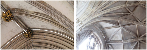
This design is found consistently throughout the cloister at Norwich, with the point at which the transverse ridge rib meets the longitudinal rib apex being approximately 0.1 m lower (). In , this lower point at the junction of the longitudinal rib apex and transverse ridge rib is labelled as ‘transverse ridge’ under the apex height data, for example in run five the longitudinal rib apex is 2.263 m, with the transverse ridge rib joining the same boss stone at a lower height of 2.156 m. This feature can be found at other sites, for example in the south transept vaults of Gloucester cathedral, which includes ribs which intersect at different levels, giving prominence to different elements (). Despite these nuances, our data indicates that the chord method and three circles method of geometric design are often found for single-centred arcs, given that they both rely on a known apex, as found in the cloister.
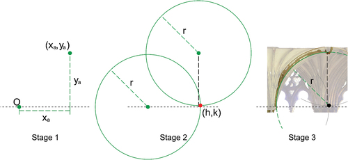
Figure 15. Norwich cathedral cloister eastern bay 7 highlighting the longitudinal rib apex joining the boss stone at higher height than the transverse ridge rib (left) and Gloucester cathedral south transept showing ribs converging at different levels.
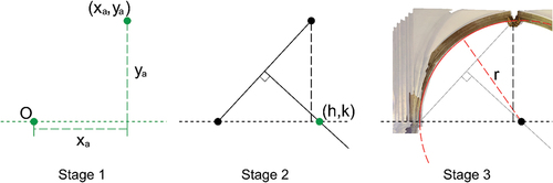
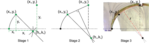
The chord method is prominent, particularly in runs one to four of the east and south walks which were designed and built first. This works first by drawing the known springing point (O), span (xa) and apex height (ya) in elevation (, stage 1), then connecting the springing point to the apex (xa,ya) with a straight line. From this line, a perpendicular bisector is created, and where this crosses the impost line gives us the arc centre point (h,k) (, stage 2), which is used to determine the unknown rib radius and complete the arc design (, stage 3). We are confident that the chord method was used for all longitudinal ribs in every bay of the cloister, and all transverse ribs in bay runs one to four (). This is most likely given that these bounding ribs appear to be used as design generators for other ribs, which is reflected in where they have distances from their centres to the impost close to 0 m. On the other hand, ribs with centre points away from the impost tend to rely on known elements from other ribs such as apexes and radii.
Figure 16. The chord method of arc design shown for a transverse rib of bay 8 (east), with the rib elevation shown as an orthophoto behind (stage 3).
The chord method is viable for both sets of tiercerons in runs one to four; however, it is also possible that the three circles method could be used here, given how similar their radii are to the transverse ribs in the eastern bay runs one to three and the longitudinal ribs in southern run four, which were likely designed first as bounding bay ribs (). The similarity of radii is significant, as it indicates that this could be transferred from one rib to another, and thus becomes a known element alongside the apexes, which we have already established are known for all single-centred ribs in the cloister. Transferring radii is advantageous for construction as it means that rib voussoirs can all be cut to the same curvature, for example the average radius of the longitudinal ribs in southern run four is 2.269 m, which is very similar to the transverse tiercerons (2.233 m) and longitudinal tiercerons (2.311 m). However, the rib profile of the longitudinal ribs and both sets of tierceron ribs still differ in this example as well as others (see Thomas’s rib profiles in ). Yet repeating the same rib curvature for multiple ribs does still decrease the complexity of construction, with only the rib profile template changing, instead of both this and the rib curvature template.
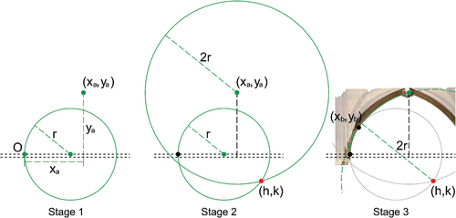
The three circles method works by first drawing the known springing point (O), span (xa) and apex height (ya) in elevation (, stage 1), followed by two circles of the known radius (r) with their centres on the springing (O) and apex (xa,ya) (, stage 2). The lower of the two crossing points of these circles gives us the missing arc centre (h,k), which is used to construct an arc of the known radius (r) and thus complete the rib (, stage 3). It is not possible to pinpoint exactly whether the chord or three circles method was used for the tiercerons in bay runs one to four given how close their arc centres are in relation to the impost (); however, the three circles method is more convincing for the transverse rib and both sets of tiercerons in run five, predominantly in the west walk, given that arc centre points sit further below the impost for both sets of tiercerons (). These rely on a radius generated using the chord method from the longitudinal rib ( and ). Given the frequent use of the three circles method in bay run five, this perhaps suggests it was also used for the earlier bay runs one to four.
Figure 17. The three circles method of arc design shown for a transverse tierceron of bay 8 (east), with the rib elevation shown as an orthophoto behind (stage 3).
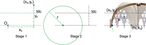
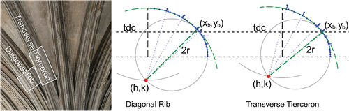
The two circles method has so far been found infrequently at sites of English medieval vaulting, given the prominence of known apexes via horizontal ridge lines. Across 14 sites, we have only found single-centred ribs that use the two circles method in three bays of a single site: the south west choir aisles at Wells cathedral. However, we have proposed the two circles method in the cloister at Norwich for the lower arc of the two-centred diagonal ribs in eastern run two, as well as the lower arc of the two-centred tiercerons and diagonal ribs in run six to the north (). For the geometric process to work a vertical line of intersection is usually required, representing the apex height (ya). However, it is also possible to use a horizontal line of intersection, in the case of bay 12, at 60% height of the vault. This height is based on analysis using Grasshopper, a visual scripting plugin for Rhinoceros 3D, where we generated best fit arcs for lower and upper rib arcs at 5% intervals, with the likely lower apex found when the two radii stabilise. This process suggested that a change in rib radii appeared to be taking place at 55–65% height of the vault in bay 12, which is also the horizontal point of transition between the lower arc forming tas-de-charge stone curvatures (tdc) into a different design for the individual rib voussoirs above, as tested via total station surveying of mortar joints (, stage 1). To find the lower apex using the two circles method, a circle is drawn of the known radius transferred from the transverse rib, for example 2.002 m in run two (), with its centre on the springing point (, stage 2). A second circle is then drawn with its centre at the intersection between the first circle and the impost level, with its circumference passing through the springing point and a horizontal line at 60% height of the bay, thus finding the missing apex xb,yb and completing the lower arc (, stage 3).
Figure 18. The two circles method of arc design shown for a lower arc of diagonal rib of bay 12 (east), with the rib elevation shown as an orthophoto behind (stage 3).
A final geometric process to create a single-centred rib is found in the diagonal ribs of run three of the cloister. These have a known apex (xa,ya) at the centre of the bay (2.084 m) and an unknown arc centre point (h,k) as it sits below the impost (−0.470 m), suggesting that the three circles method could be used. However, this relies on having a known arc radius which needs to be found from another source, for example the transverse rib radius as described for run one to three which could be transferred to the tiercerons using the three circles method. Yet, the diagonal rib radius (2.555 m) is significantly larger than all other ribs in the bay run, and it is therefore improbable that this method was used. Given that these ribs are single-centred, the most likely option is therefore the two chord method, outlined by Willis (Citation1842, 13). To create two chords rather than one, a third point along the proposed arc is required in addition to the springing (O) and apex (xa,ya), defined using the tunnel method, which we have evidence of in the south transept vaults at Pershore Abbey, as well as the high vaults of the choir at Wells cathedral.
Referring back to the middle plan of run three (), a straight line connects the transverse and diagonal ribs, with a slight retiring inward for the transverse tiercerons. This suggests that a longitudinal tunnel is being created, as the traced lines of the transverse and diagonal ribs closely overlay with each other when viewed in elevation across the bay (), hence the viability of the two chord method, which inherits a point from the curvature of a different rib. For this to be achieved, the point of intersection between the transverse rib at half the apex height ya is recorded. This height closely aligns with the top of the tas-de-charge, which is 53% of the vault height, based on detailed total station surveying of rib mortar joints. From this, apex height yb is created then transferred onto the plan to create point α. Next the line drawn to create apex height yb is continued on the plan until it crosses the diagonal rib, creating point β (, stage 1). This point represents the span xb required to form the lower apex, and is marked and then transferred to the diagonal rib in elevation along the overall rib span xa; a process that a mason could easily measure by opening out a set of dividers, or by working directly over the drawing indicated in stage 1 of . In addition to run three, we find the tunnel method in use for the two- or three-centred diagonal ribs of run one, four and five of the cloister, although run five is based on a transverse rather than longitudinal tunnel (). It is also potentially used to establish the two-centred transverse ribs in run six, to be discussed in section 6.2.
Figure 19. Half plan (bay 8, run three) showing a dashed line connecting the transverse and diagonal ribs, with close alignment of these ribs shown in black in the elevation.
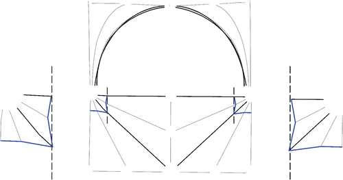
Figure 20. The two chord method of arc design shown for a diagonal rib of bay 8 (east), with the rib elevation shown as an orthophoto behind (stage 4).
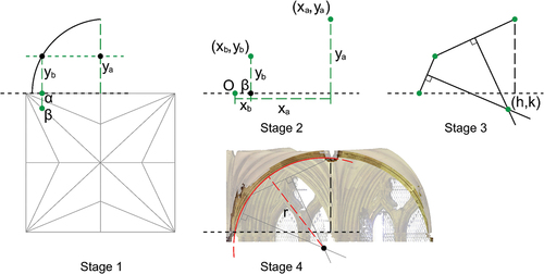
Returning to the two-chord method in run three, starting from span xb, the lower apex height yb is redrawn to find the lower apex xb,yb. This, with springing point O and upper apex xa,ya gives the three points required for this geometric process (, stage 2). Two lines are next drawn connecting the springing (O) to the lower apex (xb,yb), through to the upper apex (xa,ya). Perpendicular bisectors are created for both, with the crossing points of these lines creating the centre point h,k (, stage 3) which is used to draw the missing arc radius of the diagonal rib (, stage 4). The resulting rib does not form a pointed arch, nor is it the true semicircle suggested by Woodman (Citation1996). Instead, the rib flattens out at the apex; a feature covered by the boss.
6.2. Two-centred ribs
Willis (Citation1842, 17) outlined two methods of creating two-centred ribs, both found in the cloister at Norwich. The first is used in the diagonal ribs of run one in the east and results in an upper arc radius (3.164 m for the diagonals) that is independent to that of the lower arc (2.174 m for the diagonals), whereas his second method which appears to be found in all except the longitudinal ribs of run six in the north generates an upper radius (3.006 m for the diagonals) that is about double that of the lower arc (1.562 m for the diagonals). For these two-centred methods the lower arc needs to be designed first, and in the cloister we see examples of all three single-centred rib methods used to generate these (Section 6.1, ).
For Willis’s first two-centred method in the diagonal ribs of run one, the lower arc is first generated using the three circles method (, ). To find the diagonal’s upper arc a line is drawn from the lower arc apex (xb,yb) downwards through the arc’s centre point (hb,kb), creating a perpendicular bisector at the tangent point of the lower arc apex (, stage 1). Next, a chord is drawn connecting the lower (xb,yb) and upper arc apexes (xa,ya), followed by a perpendicular bisector (, stage 2). Where the two perpendicular bisectors intersect gives us the missing upper arc centre point (ha,ka), which is used to complete the upper arc of the diagonal rib and thus, the two-centred rib (, stage 3).
Figure 21. Willis’s two-centred unknown upper radius method of arc design shown for a diagonal rib of bay 3 (east) with the rib elevation shown as an orthophoto behind (stage 3).
In run six in the north walk, the centre point of the lower arc is consistently 0.1 m above the impost line, which is visibly evident on inspecting the springing points on site, resulting in ribs that are slightly stilted. Although the arc centres are theoretically above the impost line, the fact that an intentional decision appears to have been taken to create stilted ribs means that the arc centre in relation to the impost can be considered a known element in this run. After the single-centred longitudinal rib, the two-centred transverse rib is likely to have been designed next, with the lower arc apex defined using the tunnel method based on bays that were already in place to the west and possibly the east (bay 49). Given the known apex this provides, as well as the known arc centre in relation to the impost, the chord method could be used to complete the lower arc of the transverse rib, which then defines a radius which can be replicated for all the tiercerons and diagonal ribs using the two circles method (). There are perhaps other ways in which the lower arc radius could have been defined; however, our best evidence is the tunnel method, given its use throughout the cloister.
To find the upper arc using Willis’s second two-centred method, used for all except the longitudinal ribs in run six, the arc of radius (r) created to form the lower part of the rib is drawn as a circle (, stage 1), followed by a second circle that is double the radius (2 r) of the first, centred on the apex (xa,ya) (, stage 2). The lower crossing point of these two circles gives the centre point (h,k) of the missing upper arc, which is then added and thus used to complete the two-centred rib (, stage 3). Whilst this method appears most likely for run six given the doubling of radii between lower and upper arcs shown in , it is also possible to produce similarly convincing results using Willis’s first two-centred method. The transition point (xb, yb) between lower and upper arcs is fixed in the first, whereas this is unknown in the second method. Therefore, the masons were faced with a choice to either use the first two-centred method, where the transition point was fixed, yet upper arc radii would vary, or to use the second two-centred method, where both radii were defined resulting in an unknown transition point that could move up or down.
Figure 22. Willis’s two-centred known radius method of arc design for a transverse rib in bay 45 (north), with the rib elevation shown as an orthophoto behind (stage 3).
A detailed total station survey of the mortar joints of the ribs on the outer wall side of 45–46 was revealing. All the ribs have short voussoirs at the top of the tas-de-charge, followed by much longer ones (). Testing Willis’s second two-centred method suggested a close alignment between the transition point of the two radii with the upper mortar joint of the short rib for the longitudinal tierceron and diagonal rib in bay 45, and the diagonal rib in bay 46. On the other hand, the transition point for the transverse tierceron in bay 45 and the longitudinal tierceron in bay 46 appear to match the top of the tas-de-charge, with the remaining ribs unconvincing. Whilst inconclusive, this suggests that the masons may have understood that the transition point was higher than the top of the tas-de-charge in some cases, therefore adding a short voussoir completed the lower arc before switching to the new radius of the upper arc. This data, as well as the move towards repeating the same radius across multiple ribs in run five, supports the masons’ use of Willis’s second two-centred method in run six.
Figure 23. The transition point (green dashed line) between lower and upper arcs aligns with the top of the short rib in bay 45 for the diagonal rib, and the top of the tas-de charge for the transverse tierceron. Total station points are shown in blue.
6.3. Three-centred arches
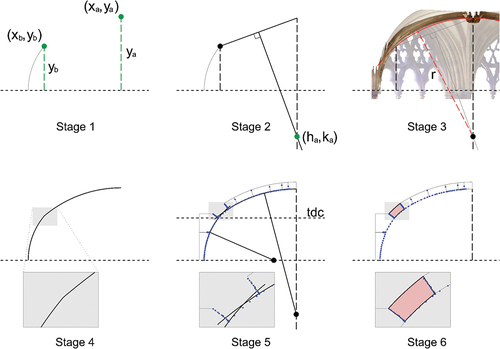
The traced lines and subsequent data for the diagonal ribs in run two, four and five suggested two-centred ribs were used. However, a satisfactory solution for the upper diagonal rib geometry was difficult to find, with neither of Willis’s two-centred methods outlined in section 6.2 offering a good fit. The closest match we could find for the upper diagonal arc in these bays uses a variation of the chord method of geometric design, where the lower apex (xb,yb), upper apex (xa,ya) and arc centre point are known, with the radius unknown (, stage 1). Analysing our data showed that the upper arc of diagonal ribs in these runs had an arc centre point (h,k) significantly below the impost line (−0.8 m in run five for example), yet when trying to identify centre points visually, it became clear that they were located at the centre of the bay vertically. This therefore resulted in the upper arcs being semi-circular when continued across the bay, thus creating a three-centred arch when combined with the lower diagonal ribs. Using the vertical centre line rather than the horizontal impost line, the missing radius was found first by drawing a chord between the lower apex (xb,yb) and upper apex (xa,ya), followed by a perpendicular bisector. Where this crosses the vertical centre line (ya) gives the arc centre point (h,k) (, stage 2), which can then be used to complete the arc (, stage 3). However, a tangent point between the lower and upper diagonal arcs could not be found, resulting in a slight angle being evident between the two rib curvatures (, stage 4). One possibility was that this was a result of settlement and loading after construction was completed; however, we have found no visual evidence of this when inspecting the vaults. Another possibility is that the medieval masons created a transitional voussoir above the tas-de-charge. Total station surveying was used to identify mortar joints for bays representing each run where this transitional voussoir potentially appears in the diagonal rib design (two, four and five), including bay 11 and 12 in run two. This data further supports the use of the chord method variation for the upper arc, with arc centres on the centre line vertically (, stage 5), and crucially, the best fit arcs created through these points appear to replicate a slight angle between the lower and upper arc. This can be seen in the first voussoir after the top of the tas-de-charge stone (, stage 5) and suggests it could have been reshaped to form a smooth transition between the upper and lower arcs (, stage 6).
Figure 24. Modified method of arc design shown for the upper diagonal rib of eastern bay 12, with the rib elevation shown as an orthophoto behind (stage 3) and the total station survey demonstrating support for a transitional voussoir (blue points, stage 5 to 6).
7. Reflections and conclusions
In extending previous research on the cloister at Norwich, we have further demonstrated the complexities of its design and the significance of the middle plan as a tool for investigating this. Rather than Willis’s single run per walk, our investigations have highlighted at least six distinct designs introduced over the 133-year construction period (). Why these differences? Clearly over such a long construction sequence, numerous different master masons were involved. They may have brought different knowledge to the site and had their own preconceptions of the three-dimensional form of a bay and the relative prominence of different ribs. Nevertheless, a new master did not always introduce a change in vault design, as demonstrated by the west walk (part of run five), where the same design was used by at least three different masters.
Design breaks could also represent a significant passing of time, when original centering and stonecutting tools were potentially lost, therefore requiring the creation of new ones. This is another option to explain why design changes were made, and could be explored as part of future research by investigating stonecutting in more detail.
Simplification of construction was also likely to be a factor, with everything potentially constricted by the pre-existing fabric. Although Willis was fascinated by the ‘ingenuity’ demonstrated by designers who reworked existing fabric to new designs (Buchanan Citation2013), his emphasis on stylistic change meant that he underplayed the significance of this aspect of medieval architecture. Our analysis reveals the complex interplay between conservation and innovation at Norwich, found also in the boss sculpture (Hawkins Citation2020), showing how nuanced and rich the process of taking on harder design challenges can be in the interest of saving construction energy (Calder Citation2021).
Another factor is likely to have been aesthetic, considering the experiential qualities of the space. Whilst the tracery of the Norwich cloister was used by Willis as both indicator and exemplar of stylistic change, nevertheless, other than from the cloister garth, the windows are only experienced sequentially so changes matter far less than they would for vaulting, which is experienced as a vista. The retention of the tierceron design, old fashioned by the fifteenth century, retained a visual consistency across the four walks. Although changes to rib curvatures have some impact on the appearance of the vault, they are minor compared to the changes in the tracery. Nevertheless, some solutions may have been selected or rejected on visual grounds.
Although minor changes to rib design such as raising the impost by 0.1 m, or extending a line from the middle plan of a transverse rib to a diagonal rib via the tunnel method might appear trivial, they have a significant impact on the overall design process and visual effect. Medieval masons might have used other methods that we are yet to discover, or maybe the subtle changes in design were more ad hoc in their adoption. However, the fact that subtleties are repeated again and again along different runs suggests this was not the case. Whilst Willis’s middle plan is used as an analytical device in this article, the tunnel method apparently found in several bay runs suggests it might also have been significant as a design device, with the medieval masons understanding that transferring a point from the transverse (or longitudinal) rib to the proposed diagonal rib would result in a prominence on the tunnel aspect of the design, emphasising the longitudinal directionality of the space over the compartmentalisation of individual bays. The range of techniques employed also suggest that the inventiveness of medieval masons was not focused solely on more visible elements such as tracery and boss design, hitherto the primary focus of art historical attention, and that even the form of the tierceron star vault could involve a wide range of geometrical design processes.
In run three, the earliest constructed, the use of the two-chord method resulted in prominent diagonal ribs. These were abandoned in subsequent designs, instead pushing back the diagonal by using either a three-centred rib in runs two, four and five, or a two-centred rib in runs one and six. Runs five to six show the increased importance of consistent rib curvatures, achieved in all but the longitudinal ribs in run six, even though the ribs have two arcs. The shift towards consistent curvatures also suggests that the three circles method might have been used in runs one to four, although we cannot be sure given the similarity of results if the chord method were used.
With limited contemporary documentation (treatises or physical drawings), we cannot be sure about the exact design processes used by medieval designers, therefore such studies involving a process of reverse engineering always include a level of uncertainty. Also, we still do not have sufficient comparative data to associate specific processes with individual designers (Hillson, Buchanan, and Webb Citation2022). However, our analysis based on evidence from digital surveys of the in-situ vaulting does give a strong indication of the different geometric methods that were probably used. The chord method seems to have been the earliest in use and is consistently employed for the longitudinal ribs, which themselves would have been congruent with the wall arches. This supports Sekules’s (Citation2006) hypothesis that the south, west and north garth walls were erected as part of one campaign. The move towards methods enabling a transfer of radii from rib to rib as construction progressed is perhaps more revealing. Although different templates were used for rib section profiles, the clear evidence of a repeated radius for the majority of ribs in run five via the three circles method, and the likely use of Willis’s two-centred known radius method in almost all ribs of run six, suggests an understanding of the simplification of the construction process that these decisions would have brought. The consistent curvatures of the conoids are comparable with those found in fan vaults, fashionable in contemporary England, first found in the cloister of Gloucester cathedral c. 1351–77.
The middle plan has not only assisted in identifying individual bay runs, but also in demonstrating where designs transitioned from one bay to the next, and the different options for how these transitions could be achieved, never the focus of previous scholarship (). Whilst mid bay transitions allowed for a more planned process, bay boundary changes suggest something more abrupt, which might even involve modifying existing fabric. Our findings in the cloister at Norwich reveal similarities with other examples of medieval vaulting, for example mid-bay design transitions in the high vaults at Exeter cathedral and asymmetrical middle plans in the choir aisles at Wells cathedral, which are associated with different master masons. Norwich cathedral cloister is a particularly intriguing case study of the issues involved, given the 49 bays built over a period of 133 years.
Acknowledgments
The research would not have been possible without JR Peterson and Sarah Duffy (University of Liverpool), who helped gather and process the data. Thanks also to Norwich cathedral, particularly Roland Harris, who facilitated access to the site and shared an extensive set of CAD drawings which informed our research (Thomas Citation1999).
Disclosure statement
No potential conflict of interest was reported by the authors.
Data availability statement
The data that support the findings of this study are openly available in the Archaeology Data Service at https://doi.org/10.5284/1091202 reference number 4190.
Correction Statement
This article has been republished with minor changes. These changes do not impact the academic content of the article.
Additional information
Funding
References
- Alexander, J. 2006. Lincoln cathedral cloister. Journal of the British Archaeological Association 159 (1):222–48. doi:10.1179/174767006x133005.
- Binski, P. 2014. Gothic wonder: Art, artifice and the decorated style 1290–1350. New Haven and London: Paul Mellon and Yale University Press.
- Buchanan, A. 2013. Robert Willis (1800-1875) and the Foundation of Architectural History. Woodbridge: Boydell Press.
- Buchanan, A., J. Hillson, and N. Webb. 2021. Digital analysis of vaults in english medieval architecture. London: Routledge.
- Calder, B. 2021. Architecture: From prehistory to climate emergency. London: Pelican.
- Fernie, E. 1993. An architectural history of Norwich Cathedral, 166–67. Oxford: Clarendon.
- Fernie, E. 1996. The building: An introduction. In Norwich Cathedral: Church, City and Diocese, 1096– 1996, eds. I. Atherton, E. Fernie, C. Harper-Bill, and H. Smith, 47–58. London:Hambledon Press.
- Harris, R. 2019. Reconstructing the Romanesque Cloister at Norwich Cathedral. The Antiquaries Journal 99:1–27. doi:10.1017/S0003581519000118.
- Harvey, J. 1984. English mediaeval architects: A bIographical dictionary down to 1550. Gloucester: Sutton Publishing Ltd.
- Hawkins, R. 2020. Questions of sculptural idiom in the later bosses from Norwich Cathedral cloister (c.1411-1430). PhD diss., University of Cambridge. 10.17863/CAM.57362
- Heywood, S. 1996. The Romanesque building. In Norwich Cathedral: Church, City and Diocese, 1096– 1996, eds. I. Atherton, E. Fernie, C. Harper-Bill, and H. Smith, 73–115. London:Hambledon Press.
- Hillson, J., A. Buchanan, and N. Webb. 2022. Tracing the past: A digital analysis of the choir vaults at wells cathedral and ottery saint mary. In The Analysis of Gothic Architecture: Studies in Memory of Robert Mark and Andrew Tallon, ed. R. Bork, Vol. 14. 212–37. Brill.
- Maddison, J. 2000. Ely Cathedral: Design and meaning. Ely: Ely Cathedral Publications.
- Maira Vidal, R. 2017. The evolution of the knowledge of geometry in early gothic construction: The development of the sexpartite vault in Europe. International Journal of Architectural Heritage 11 (7):1005–25. doi:10.1080/15583058.2017.1332254.
- Monckton, L. 2006. Experimental architecture? Vaulting and West Country Cloisters in the late middle ages. Journal of the British Archaeological Association 159 (1):249–83. doi:10.1179/174767006x133014.
- Saunders, H. W. 1939. The first register of Norwich Cathedral Priory. A transcript and translation. In Norfolk Record Society, edited by P.Millican, Vol. 11. 50– 51. Norwich: Norfolk Record Society Publications.
- Sekules, V. 2006. Religious politics and the cloister bosses of Norwich Cathedral. Journal of the British Archaeological Association 159 (1):284–306. doi:10.1179/174767006x147451.
- Stewart, M. 2009. Patterns of eternity: Sacred geometry and the starcut diagram. Stourbridge: Floris Books.
- Stewart, D., and R. Willis. 1875. Notes on Norwich Cathedral. Archaeological Journal 32 (1):16-47 and 155–87. doi:10.1080/00665983.1875.10851672.
- Thomas, P. 1999. Norwich cathedral cloister total station survey. Unpublished data.
- Webb, N., and A. Buchanan. 2019. Digitally aided analysis of medieval vaults in an English cathedral, using generative design tools. International Journal of Architectural Computing 17 (3):241–59. doi:10.1177/1478077119866126.
- Webb, N., J. Hillson, and A. Buchanan. 2021. Two- and three-dimensional geometry in tierceron vaults: A case study of the cloister at Norwich Cathedral. Proceedings of the Seventh International Congress on Construction History, Lisbon, Vol 2, 71–77.
- Wendland, D. 2019. Steinerne Ranken, wunderbare Maschinen: Entwurf und Planung spätgotischer Gewölbe und ihrer Einzelteile. Petersberg: Imhof Verlag.
- Whittingham, A. 1980. Report of the summer meeting of the royal archaeological institute at Norwich in 1979. Archaeological Journal 137 (1):280–368. doi:10.1080/00665983.1980.11078483.
- Willis, R. 1842. On the construction of the vaults of the middle ages. Transactions of the Royal Institute of British Architects 1 (2):1–69.
- Woodman, F. 1996. The Gothic campaigns. In Norwich Cathedral: Church, City and Diocese, 1096– 1996, eds. I. Atherton, E. Fernie, C. Harper-Bill, and H. Smith, 158–96. London:Hambledon Press.