Abstract
There is a need to develop quantitative evaluation for simulator based training in medicine. Photoelastic stress analysis can be used in human tissue modeling materials; this enables the development of simulators that measure respect for tissue. For applying this to endovascular surgery, first we present a model of saccular aneurism where stress variation during micro-coils deployment is measured, and then relying on a bi-planar vision system we measure a catheter trajectory and compare it to a reference trajectory considering respect for tissue. New photoelastic tissue modeling materials will expand the applications of this technology to other medical training domains.
NOMENCLATURE
| C | = |
photoelastic coefficient |
| C T | = |
point belonging to the catheter centerline |
| c x , c y , c z | = |
catheter tip spatial coordinates |
| D | = |
optical path length |
| D XY , D XZ | = |
optical path length images |
| F XY , F XZ | = |
number of pixels belonging to the blood vessel model |
| G XY , G XZ | = |
deformation value |
| Hi | = |
studied trajectory |
| i | = |
index for trajectory number |
| I | = |
number of source trajectories |
| I bmax | = |
maximum of blue light intensity |
| I Gmax | = |
maximum of green light intensity |
| I Gmin | = |
minimum of green light intensity |
| I GN | = |
intensity of the emerging light beam |
| k | = |
index for video frame number |
| Li | = |
source trajectory |
| n | = |
reference trajectory frame number |
| p n | = |
number of points belonging to L i occurring after t n-1 and before t n |
| R | = |
reference trajectory |
| Re | = |
retardation of polarized light |
| SR | = |
sampling rate for a trajectory |
| S x,y | = |
noise indicator for pixel located in column x row y |
| T | = |
number of frames defining a trajectory |
| t n | = |
normalized time |
| x | = |
space coordinate corresponding to image column number |
| y, z | = |
space coordinates corresponding to image row numbers |
| λex | = |
characteristic wave of the quarter-wave plates |
| λG | = |
emerging light beam wave length |
| σ1, σ2 | = |
sides of a biaxial stress field |
| σXY, σXZ | = |
percentage of pixels with stress above threshold value |
| θ | = |
biaxial stress field direction |
1. INTRODUCTION
The technology for simulator based training in medicine is being developed to correspond to the technological advances in minimally invasive surgery. Surgery invasiveness is directly related to the respect for tissue (how much the tissue integrity is preserved during the treatment). Therefore it is desirable to measure the respect for tissue in these simulators to provide a quantitative evaluation during the training. For showing the potential of this measurement technology, in this article we present an overview of the available systems for that purpose in the endovascular surgery domain. To show sensibility, we present a thin walled model of a saccular aneurysm for measuring the risk of rupture that represents the deployment of the release mechanism of a micro-coil, and finally a bi-planar vision system that enables catheter trajectory analysis based on a reference trajectory and that includes respect for tissue by measuring the motion of the catheter tip, deformation of the membrane, and stress variation within the membrane.
The benefits of simulator based training has been shown for endovascular intervention by (Chaer et al. Citation2006) and for endoscopic intervention by (Kunkler Citation2006). They found that the use of simulators during training improves resident's performance, decreases the risk to patient's safety during supervised practice, and reduces the instruction time. Global Rating Index for Technical Skills (GRITS) for medical training were introduced for laparoscopic surgery in (Moorthy et al. Citation2003) and extended later on in (Doyle et al. Citation2007), both of them consider as first evaluation criteria the respect for tissue. The simulators for endovascular intervention may be classified into two groups corresponding to the approach used for human vasculature modeling: hardware or software.
Simulators based on virtual reality environments for blood vessel modeling, reproduce also in software the motion of the catheters and guide wires as well as other intravascular tools deployment. The intravascular devices and blood vessel interaction is transmitted to the operator using force feedback at the insertion port. These ports accept a limited number of standard catheter and guide wires without lubrication. Contrast media injection is simulated by air injection in a secondary port. However inside the virtual reality, a large number of intravascular devices and blood vessel morphologies and diseases are selectable (Chaer et al. Citation2006).
In early stages vasculature modeling in hardware was done using glass (Willems et al. Citation2009). Then merging to softer and transparent materials, models of human vasculature were built from corrosion cast of vascular lumen of diseased human specimen (Gailloud et al. Citation1997). More advanced modeling techniques are based on silicone elastomer, and enable DICOM data fusion, reproduce the human vasculature lumen with 13 µm of accuracy, have an elastic modulus of 2 MPa (human vasculature elastic modulus: 1-3 MPa), and its friction coefficient can be set at 0.042 (Ikeda et al. Citation2005). These simulators offer the advantage that enable to insert any standard intravascular devices into the silicone vasculature, and offer a realistic representation of the interaction between these devices, human blood vessel morphology, and flow circulation. Figure (a) shows the simulation of an embolization using a silicone model of a cerebral aneurysm; flow within the model is visualized by the injection of minute bubbles. This type of simulation does not enable measuring the aneurysm tissue integrity.
Figure 1 (a) Embolization simulation in silicone model of cerebral aneurysm. (b) Birefringence produced by stress on photoelastic membrane with a 0.8 mm diameter guide wire. The guide wire is applying a force of 0.3 N to the membrane.
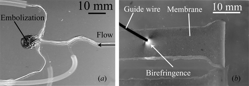
Photoelastic stress analysis, using a transmission polariscope, relates the stress within the material with birefringence that is produced by the phase shift that polarized light undergoes while passing through the studied material. Figure (b) shows a raw image of a membrane (with a 2 mm thickness) placed within the polariscope shown in Figure (c). Birefringence is observed while a force of 0.3 N is applied with a medical use guide wire. Modeling human vasculature with transparent photoelastic materials enables stress visualization and analysis. For including GRITS in endovascular surgery simulation we selected this technology as it enables representation of respect for tissue during the simulation.
2. OVERVIEW OF PHOTOELASTIC STRESS ANALYSIS ON VASCULATURE MODELS
In photoelastic stress analysis, stress is calculated from measurements of light intensity. The polarized light phase shift is called retardation. The difference between the principal stresses on each side of a biaxial stress field σ1, σ2 relates with retardation with the following equation (while the emerging light beam is perpendicular to plane described by σ1, σ2):
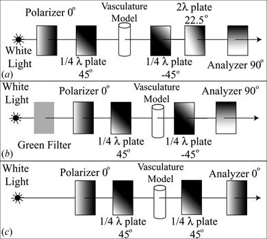
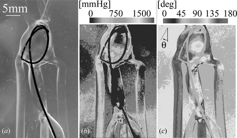
The polariscope shown in Figure (a) was used in combination with single layer models of urethane elastomer for simultaneous measurement of stress magnitude and direction while a guide wire was inserted into the model of a giant aneurysm (Ikeda et al. Citation2006). This configuration maximizes the color diversity produced by the angular components of the stress and gives an excellent contrast between analysis region and intravascular tools. However its accuracy may be compromised by the accuracy of the wave-plates wavelength, Figure .
Figure 3 (a) Photoelastic image of guide wire inserted into a single layer model of a giant aneurysm, and its corresponding: (b) Stress magnitude analysis and (c) Stress direction analysis.
For maximizing the accuracy of the stress magnitude analysis the polariscope shown in Figure (b) was used with multilayer models of vasculature. After measuring the photoelastic coefficient and the blue light transmittance coefficient of urethane elastomer, there was an average error of 3.9% in stress magnitude measurements for the pressure range of 60–200 mmHg (Tercero et al. Citation2010), Figure . In this polariscope the relation between the green light intensity and retardation is described by:
Figure 4 (a) Photoelastic image of multilayer blood vessel model, light brightness is produced by inner pressure within the model. (b) High accuracy photoelastic stress analysis of the model shown in (a). A local maximum of stress appears in the right side of the studied region.
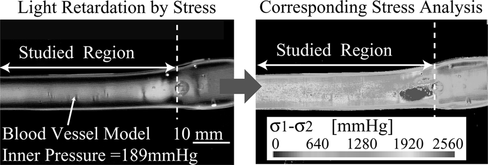
Figure 5 (a) Photoelastic image of saccular aneurysm with bleb. (b) Stress analysis for saccular aneurysm model with bleb and inner pressure of 115 mmHg.
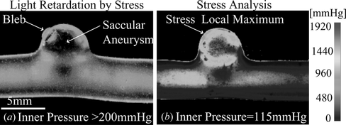
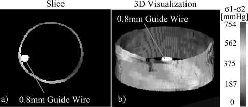
Figure 6 (a) Slice showing the cross-section of the stress field and guide wire reconstructed from sinograms using the Maximum-Likelihood Expectation-Maximization method. (b) Three-dimensional visualization of the stress within the blood vessel and of the guide wire.
3. MATERIALS AND METHODS
3.1. Stress Analysis during Micro-Coil Deployment in Saccular Aneurysm
For showing the potential of this technology for in-vitro measurement of the stress produced by intravascular implants, the deployment of a micro-coil in a saccular aneurysm was studied. The stiffness of the release mechanism of these implants is higher than implant itself. The deployment of such mechanism into the aneurysm has to be avoided during endovascular intervention, as it may compromise the vasculature tissue integrity.
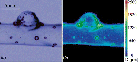
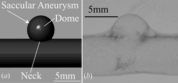
A model of a saccular aneurysm with 4.8 mm height and a neck diameter of 3.6 mm was designed, and then constructed with a thin layer configuration using rapid prototyping, deep coating in urethane elastomer (Nipolan 5120 dyed yellow with I-01-001Y Epoch at 0.1 wt%), and lost wax method. The CAD design of the aneurysm is shown in Figure (a) and the model of the aneurysm under white light source in Figure (b). The model filled with a glycerin solution at 50%, was placed inside a glycerin tank.
Figure 7 (a) Design of the aneurysm morphology. (b) Single layer model of saccular aneurysm built with urethane elastomer under white light source.
For using equation (1) the photoelastic coefficient of the material C should be known and the thickness of the material D and the retardation of the emerging light beam Re must be measured. C = 1.284 × 10⁻⁹ Pa−1 was measured for this material in (Tercero et al. Citation2010). For this material D can measured using the blue light transmittance as described in (Tercero et al. Citation2010). For the polariscope shown in Figure (c), the relation between the normalized green light intensity and retardation is described by:
An image of the model under blue light was captured for measuring the optical path length D. Then the blue filter was exchanged by the polariscope shown in Figure (c), and a micro-coil was delivered within the aneurysm until the release mechanism touched the aneurysm model wall. Images of the process where registered and analyzed.
3.2. Bi-Planar Vision System for Catheter Trajectory Analysis
3.2.1. Vasculature model and vision system
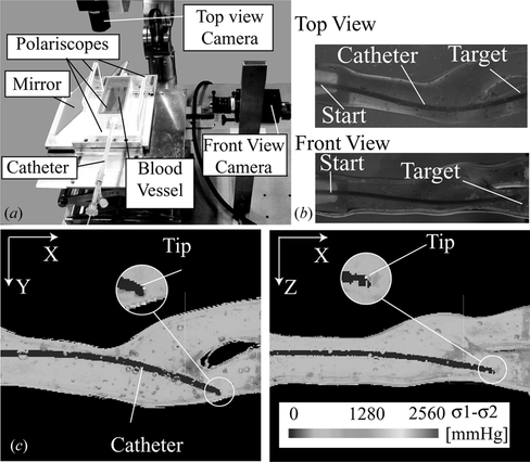
In this experiment we used a multilayer model of a carotid artery constructed in the same way as (Tercero et al. Citation2010), filled and submerged in glycerin. We selected the polariscope shown in Figure (c) for the real time analysis due to the contrast quality and simplifications enabled by the mathematic model. The pressure inside the model remained below 40 mmHg during the experiment. By aligning the model's principal branch axis parallel to the X-axis of both cameras in a stereovision vision system with perpendicular cameras pointing to the model, the progression of the catheter trajectory is principally perceived at X-axis and branch selection at Y and Z axes. Respecting this principle, the cameras were aligned to the tank containing the blood vessel model. A polariscope was placed parallel to each camera plane and having the blood vessel model in between their quarter-wave plates. The beams from a single light source were separated to pass through each polariscope. Toshiba IKTF-2 cameras were used for the stereovision system and Micro Technica MTPCI-DC2 as video capture boards. This enabled to load video frames of 640 × 480 pixels to a dynamic memory array with a maximum delay of 15 ms. The video frames were captured and processed in different computers for each plane; they were synchronized through TCP/IP for exchanging trajectory analysis results. For this analysis we use a region of interest of 640 × 260 pixels containing the entire blood vessel model, Figure (a–b). The pixel size is 111 µm in this experiment.
Figure 8 (a) Bi-planar vision system for real-time catheter trajectory analysis adapted for a carotid artery vasculature model. (b) Example of the captured images with the bi-planar vision system, showing the catheter inserted from the start point to the target branch. (c) Example of the result image of the catheter trajectory analysis done at 3 fps, which includes: photoelastic stress analysis, deformation measurement, and catheter tip tracking.
3.2.2. Filtering
To quantify respect for tissue during endovascular surgery simulation, it is desirable to measure in real time the stress within the blood vessel model wall and its deformation, and then relate those measurements to the actual catheter tip location within the model. For that purpose, first it is necessary to diferentiate from the background of photoelastic images the parts belonging to the blood vessel model and the parts belonging to the catheter, and then locate the catheter tip into the image.
To distiguish between these three regions we use two static images for each plane. For the XY-plane, L
XY,i,k
is the frame number k of a source trajectory video , the optical path length image D
XY
and the first frame of the studied trajectory L
XY,i,0
. The first one is used to calculate the stress value, D
XY
is deduced from the blue light transmittance using the method described in (Tercero et al. Citation2010). For preventing noise in this image we calculate the noise indicator S
x,y
for each pixel of D
XY
:
where D x,y is the optical path length at the pixel located in the row x of the column y (n′ is the mute index for each sum). If S x,y is below 4000 and D x,y is above 200 µm, then D x,y is considered noise and equalled to zero. The same considerations are taken in XZ-plane for S x,z and D x,z .
The second static image is the first frame of the source trajectory, L XY,i,0 is used for comparing the shape and luminace of the studied frame with the original conditions. At L XY,i,0 the catheter in not present and the model has no deformation in all cases, from it the luminance value of the pixels belonging to the model is registered. For L XY,i, k , a pixel belongs to the model if its luminance value is above 56 and identified as deformation if its corresponding pixel in L XY,i,0 belongs to the background. A reduction on the luminance value respect to L XY,i,0 and with values below 68 in the red channel and 55 in the blue were considered as part of the catheter. Respective threshold values of 56, 70 and 65 for L XZ,i,0 and L XZ,i,k in XZ-plane.
3.2.3. Stress and deformation measurement
For the pixels identified as part of the blood vessel model in both planes, stress is calculated using equation (1) for each pixel. The optical path length is obtained from D XY .
The calibration method for the stress analysis presented in (Tercero et al. Citation2010) was used. If we consider that the quarter plates have the same wave length than the emerging beam, the green light intensity relation with retardation can be approximated by equation (3). Using the nomenclature of (Tercero et al. Citation2010), the calibration values for XY-plane are: I bmax = 181.92, I Gmin = 51, I Gmax = 225.5. Similar equations and respective calibration values of 184.78, 29.5, and 225 were used to calculate the stress for XZ-plane. For each frame, during the stress analysis the pixels with stress above 640 mmHg were counted, the percentage of pixels represented by σ XY,i,k and σ XZ,i,k is calculated from the total number of pixels belonging to the model.
The blood vessel membrane deformation is obtained from comparing the area that belongs to the vasculature model in pixels between the two consecutive frames using:
3.2.4. Tip search
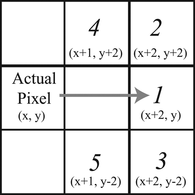
Let's suppose that for frame L XY,i,k-1 the tip was found pixel (c x, k-1 ;c y,k-1 ). For frame L XY,i,k the search starts then at the pixel (c x,k-1 , −40; 0). Every even row in column c x,k-1 will be inspected for a pixel belonging to the catheter, if found then the inspection direction changes following the priorities described in Figure for a radius of 2 pixels. If the pixel located in the direction with highest priority does not belong to the catheter, the following priority is inspected. If the next pixel belonging to the catheter is found, then search moves to that pixel and repeats the inspection in radius 2. If not, the search radius increases to 10 pixels in the same directions and priorities. If there are no pixels belonging to the catheter in both ranges it means that the catheter tip location (c x, k ; c y, k ) was found for frame k. For speeding up the search and enable motion capture during the catheter extraction, if c x,k > 60 the search for L XY,i,k+1 starts at column c x,k −40. For other cases the search starts in column 20. This way the catheter tip coordinates are determined for both planes.
3.2.5. Reference trajectory construction considering respect for tissue
The image processing software described in the previous section was used for stress analysis, morphology extraction, catheter recognition, and catheter tip detection in XY-plane and XZ-plane cameras. A point belonging to a source trajectory is defined as:
Let's name T Li the amount of frames captured between the catheter tip detection at the start point until it reaches the target for trajectory L i . To be compared these trajectories must be normalized in time, the normalized frame rate for each trajectory is obtained from the inverse of T Li and named SR Li . And for all trajectories to be represented at least with a point during a reference trajectory point construction, the reference trajectory normalized frame rate SR R is obtained from:
3.2.6. Three-dimensional approximation of catheter shape and vasculature model morphology
The cylindrical shape of the catheter and the bi-planar vision system enables to approximate the catheter cross-sections parallel to YZ-plane as ellipses which principal axes are parallel to Y and Z axes. For constructing the elliptic approximation we need to measure the length of each one the principal axes of the ellipse and know the location of their intersection. For that purpose, the images obtained from the trajectory analysis (as the ones shown in Figure (c)) were analyzed off-line. Let's define C T (C x , C y , C z ) as a point belonging to the catheter centerline located at the column C x of a pair of corresponding images. A scan is performed in the column C x for each image to detect the borders of the catheter located at B 1y (C x ,c y1 ), B 2y (C x ,c y2 ), B 1z (C x ,c z1 ), B 2z (C x ,c z2 ). The size of the ellipse axes is given by c y2 −c y1 and c z2 −c z1 . The other components of C T are given by C y = c y1 + (c y2 −c y1 )/2 and C z = c z1 + (c z −c z1 )/2. On the same way the elliptical approximation was applied for the blood vessel morphology. The obtained ellipse characteristics were written for each column into a script for Rhinoceros enabling rendering the ellipses, lofting them as a surface and then creating a mesh over them for 3-D visualization of the shape approximation of the catheter and blood vessel morphology.
4. RESULTS
4.1. Stress Analysis during Micro-Coil Deployment in Saccular Aneurysm
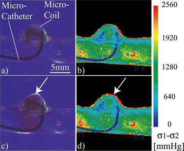
The optical path length measurement and its corresponding source image of blue light transmittance are shown in Figure . From this measurement we can estimate the aneurysm wall thickness in dome area in about 200 µm. Figures (a) and 11(c) show raw images of the embolization used for the stress analysis, where only the coil is deployed and when the coil and the release mechanism are deployed respectively. White arrows point at a local maxima of stress produced by the release mechanism deployment that reaches the 2560 mmHg of the scale (Figure (c–d)), this region has values between 1280 and 1920 mmHg while the coil is deployed correctly (Figure (a–b)).
4.2. Reference Trajectory Construction
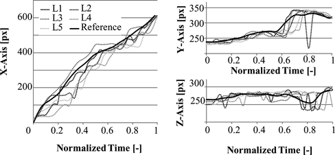
Figure , shows the variation in normalized time for the spatial components of the trajectories L 1 -L 5 and the resulting reference trajectory R obtained by applying equation (11) to these components. The componets of R corresponding to respect for tissue are shown in Figure 15.
4.3. Three-Dimensional Approximation of Catheter Shape and Vasculature Model Morphology
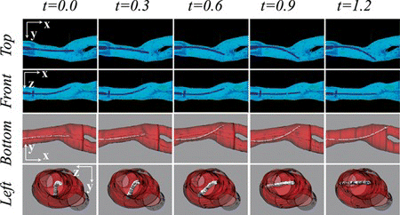
The catheter shape and morphology reconstruction using the elliptical approximation is shown for a sequence of 5 images sets that are shown in Figure . These images corresponds to the moment while the catheter is rotating for a branch selection. The approximation enabled to estimate the interaction between the catheter and vasculature model wall in YZ-plane. This three-dimensional visualization enables to perceive in a comprehensive way the shape of the catheter within the blood vessel model.
4.4. Catheter Trajectory Comparison
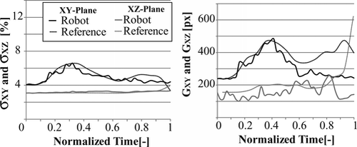
The reference trajectory construction method was used for comparison of different catheter trajectories in bi-planar and mono-vision configurations. For the bi-planar configuration the reference trajectory shown in Figure was used, and the catheter was driven with the robot used in (Tercero et al. Citation2007). In normalized time, the motion of the catheter, and variations of stress and deformation are shown in Figures and . From the trajectory plots we can see that the progression of the catheter in X-axis is smooth and stops between t = 0.5 and t = 0.7 while the rotation for branch selection is performed, at the same time the slope of the plots in Y and Z axes increases. Stress and deformation levels remain below the reference almost along the entire trajectory. The robot takes 14.3 s to complete the trajectory. The average time consumed for analysis each image set using the bi-planar vision system is 318 ms. The tip was detected within a range of 5 pixels from the real position with a 100% success rate in XY and one of 96.55% in XZ.
Figure 14 Plots of catheter tip motion capture with the bi-planar vision system, comparing the robotic manipulation to the reference trajectory.
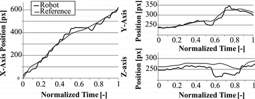
Figure 15 Plots stress and deformation variation with the bi-planar vision system, comparing the robotic manipulation to the reference trajectory.
For the mono-vision configuration, a vasculature model with similar morphology as the one shown in Figure was used. We compare the catheter motion and stress levels variation of a different reference trajectory with trajectories while the catheter was driven by inexperienced human and the robot. The reference trajectory was constructed from a set of five trajectories too. Trajectory and stress variation plots in normalized time are shown in Figure when the catheter is driven by human and in Figure when driven by robot.
Figure 16 Catheter driven by inexperienced person. Catheter tip tracking in normalized time for both axes, stress level variation in normalized time in XY-plane. Arrows point at each trial made by the user in the trajectory plot, and to the stress maxima in XY plane.
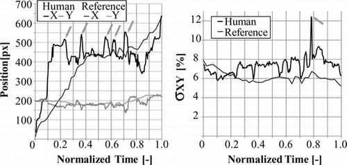
Figure 17 Catheter driven by robot. Catheter tip tracking in normalized time for both axes, stress level variation in normalized time in XY-plane.
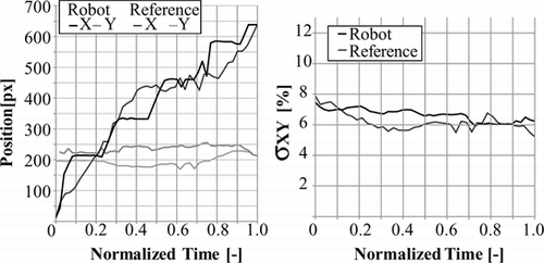
From the comparison of the catheter motion with the stress variation in normalized time we can deduce that: The inexpert user succeeds to enter the correct branch after six trials, the back and forth motion is shown in Figure where the value of c x has local maxima at t = 0.26, t = 0.34, t = 0.52, t = 0.63 and t = 0.77 before reaching the target. At t = 0.70 the inexpert user has inserted the catheter into a branch not leading to the target, and then pulls back the catheter between t = 0.70 and t = 0.84 from pixel (530; 157) to (339; 188), during that motion the stress level reached its global maximum at 12.43% of pixels with stress above 1280 mmHg. The average stress value along the trajectory is 7.31%. During the robotic manipulation, Figure shows a variation of c x corresponding to the stepping motion of the catheter insertion robot, and shows an insertion to the correct branch in the first trial. The average stress value along the trajectory is 6.61% and its global maximum is 7.44%. From the comparison of Figures with t 17, we can say that the configuration and control strategy used in the experiment corresponding to Figure enabled staying closer to the reference trajectory keeping the stress levels near or below the reference trajectory.
5. DISCUSSION
From the overview and experimental data presented in this article we can see that vasculature modeling with photoelastic materials enabled us to visualize the stress produced by standard intravascular tools such as guide wires, guide catheters, micro-coils, and micro catheters. We are able to represent numerical respect for tissue integrity for simulator-based training in endovascular surgery by enabling different kinds of stress analysis. Silicone elastomer is a photoelastic material, with excellent mechanical properties for blood vessel modeling; however its photoelastic coefficient is too low for enabling a practical measurement of stress produced by endovascular instruments to blood vessel models. On the other hand urethane elastomer has a larger photoelastic coefficient improving its sensitivity for measuring the stress produced by human blood pressure ranges or by intravascular tools. Single layer models of urethane elastomer with low wall thickness have shown to have enough sensitivity to produce birefringence with the stress produced by micro-coil release mechanism but it is desired to increase this sensitivity to analyze with more detail the complete coil delivery process. Single layer models of urethane elastomer suffer plastic deformation for pressures in the range of 60–200 mmHg. This plastic deformation is drastically reduced by shielding the urethane layer with silicone elastomer layers.
The 3-D scanner of (Matsushima et al. Citation2011) was able to register the stress produced by the guide wire to the blood vessel wall; however several seconds are necessary to collect the data and calculate the reconstruction of the three-dimensional model of the stress field and guide wire. This enables the study of the stress produced by intravascular tools after being deployed, as a stent delivered in a model of stenosis, but is a limitation for real time analysis of the catheter progress. On the other hand the bi-planar vision system enabled to relate the catheter tip motion capture and respect for tissue parameters at 3 fps, enabling catheter trajectory catheter trajectory analysis and logging for person and device profiling. This processing speed can be increased by reducing the resolution of the analysis, by focusing the analysis to a region of interest or increasing the computing power. This analysis area, time, and resolution should be configured for specific applications.
The presented examples of micro-coil release system deploy and the catheter manipulation by inexperienced person shows that photoelastic stress analysis and the vision system made possible to visualize and identify behaviors that may compromise tissue integrity by misuse and repeated trials to achieve a task. Actually there are at least nine catheters and guide wires driving devices (Govindarajan et al. Citation2010), and an autonomous catheter insertion system to reconstruct catheter trajectories through vasculature phantoms relying on magnetic trackers (Tercero et al. Citation2007). The measurement of respect for tissue while these robotic systems are manipulating the catheter is useful for designing and for demonstration of the reliability of those robotic systems.
Time and Motion is another criterion included in GRITS, in this research the time to reach a predefined target is measurable, and also unnecessary movements were visible in Figure by the inexperienced user, such kind of motion was not visible during both robotic manipulations. However the analysis is focused in the catheter tip, motion of the user hands may give also traces of unnecessary motion. Additional indicators for separating novice and expert may come also from the catheter shape analysis during the simulation and could be achieved using the 3-D approximation of Figure .
To apply the presented methodology for simulator based training, other evaluation criteria of GRITS must be included, such as bimanual dexterity, instrument knowledge, knowledge of the procedure, and flow of operation. For that the vision system must be adapted to enable tracking simultaneously a guide catheter and a guide wire, as well as the consideration of the motion capture of the catheter within the catheter insertion port and motion capture of the operator's fingers.
6. CONCLUSION
In this article two examples where given of how respect for tissue can be represented and measured during endovascular surgery simulation using photoelastic stress analysis and image processing. The applications of the presented system will increase by studying photoelastic materials for modeling large vasculature sections and with high photoelastic coefficient. The research on these photoelastic materials and modeling techniques will enable modeling other organs of human body for simulation systems in other fields of minimally invasive surgery.
ACKNOWLEDGMENTS
This research was done with the partial support of the Global Center of Excellence for Education and Research of Micro-nano Mechatronics of Nagoya University and the A-Step program of the Japan Science and Technology Agency.
REFERENCES
- Chaer , Rabih A. , Brian G. DeRubertis , Stephanie C. Lin , Harry L. Bush , John K. Karwowski , Daniel Birk , Nicholas J. Morrissey , Peter L. Faries , James F. McKinsey , and K. Craig Kent . 2006 . Simulation improves resident performance in catheter-based intervention . Annals of Surgery 244 ( 3 ): 343 – 352 .
- Doyle , Jeffrey D. , Eric M. Webber , and Ravi S. Sidhu . 2007 . A universal global rating scale for the evaluation of technical skills in the operating room . The American Journal of Surgery 193 : 551 – 555 .
- Gailloud , P. , J. R. Pray , M. Muster , M. Piotin , J. H. D. Fasel , and D. A. Rufenacht . 1997 . An in vitro anatomic model of the human cerebral arteries with saccular arterial aneurysms . Surgical and Radiologic Anatomy 19 : 119 – 121 .
- Goldstein , D. 2003 . Polarized Light . New York : Marcel Dekker Inc .
- Govindarajan , Srimathveeravalli , Thenkurussi Kesavadas , and Xinyan Li . 2010 . Design and fabrication of a robotic mechanism for remote steering and positioning of interventional devices . International Journal of Medical Robotics and Computer Assisted Surgery 6 ( 2 ): 160 – 170 .
- Ikeda , Seiichi. , Fumihito Arai , Toshio Fukuda , Makoto Negoro , and Keiko Irie . 2005 . An in vitro patient specific biological model of the cerebral artery reproduced with a membranous configuration for simulating endovascular intervention . Journal of Robotics and Mechatronics 17 ( 3 ): 327 – 333 .
- Ikeda , Seiichi. , Fumihito Arai , Toshio Fukuda , Makoto Negoro , Keiko Irie , and Ikuo Takahashi . 2006 . Patient-specific neurovascular simulator for evaluating the performance of medical robots and instruments Proceedings of IEEE-ICRA 625–630.
- Kunkler , Kevin. 2006. The role of medical simulation: An overview. International Journal of Medical Robotics and Computer Assisted Surgery 2: 203–210.
- Kuske , A. and G. Robertson . 1974 . Photoelastic stress analysis . London : Wiley-Interscience .
- Matsushima , Motoki. , Carlos Tercero , Seiichi Ikeda , Toshio Fukuda , Fumihito Arai , Makoto Negoro , and Ikuo Takahashi . 2011 . Photoelastic stress analysis in blood vessel phantoms: Three-dimensional visualization and saccular aneurysm with bleb . International Journal of Medical Robotics and Computer Assisted Surgery 7 ( 1 ): 33 – 41 .
- Moorthy , Krishna. , Yaron Munz , Sudip Sarker , and Ara Darzi . 2003 . Objective assessment of technical skills in surgery . British Medical Journal 327 : 1032 – 1037 .
- Tercero , Carlos. , Seiichi Ikeda , Tomomi Uchiyama , Toshio Fukuda , Fumihito Arai , Yuta Okada , Yoshinari Ono , Ryohei Hattori , Tokunori Yamamoto , Makoto Negoro , and Ikuo Takahashi . 2007 . Autonomous catheter insertion system using magnetic motion capture sensor for endovascular surgery . International Journal of Medical Robotics and Computer Assisted Surgery 3 ( 1 ): 52 – 58 .
- Tercero , Carlos , Seiichi Ikeda , Motoki Matsushima , Toshio Fukuda , and Makoto Negoro . 2010 . Photoelastic Stress Analysis Error Quantification in Vasculature Models for Robot Feedback Control . IEEE/ASME Trans. on Mechatronics 15 ( 4 ): 520 – 526 .
- Willems , M. C. M. , J. Adam Van der Vilet , V. Williams , L. J. Schultze Kool , D. Bergqvist , and J. D. Blankensteijn . 2009 . Assessing endovascular skills using the simulator for testing and rating endovascular skills (STRESS) machine . European Journal Vascular and Endovascular Surgery 37 : 431 – 436 .
