Abstract
Polarization based interferometers for single snap-shot measurements allow single frame, quantitative phase acquisition for vibration insensitive measurements of optical surfaces. Application of these polarization based phase sensors requires the test and reference beams of the interferometer to be orthogonally polarized. As with all polarization based interferometers, these systems can suffer from phase dependent errors resulting from systematic polarization aberrations. This type of measurement error presents a particular challenge because it varies in magnitude both spatially and temporally between each measurement. In this article, a general discussion of phase calculation error is presented. We then present an algorithm that is capable of mitigating phase-dependent measurement errors on-the-fly. The algorithm implementation is non-iterative providing sensor frame rate limited phase calculations. Finally, results are presented for both a high numerical aperture system, where the residual error is reduced to the shot noise limit, and a system with significant birefringence in the test arm.
NOMENCLATURE
| a y | = |
Amplitude of numerator term |
| a x | = |
Amplitude of denominator term |
| D | = |
Denominator term of phase calculation |
| D t | = |
Transformed denominator term |
| N | = |
Numerator term of phase calculation |
| N t | = |
Transformed numerator term |
| T | = |
Transformation matrix |
| x o | = |
Offset of denominator term |
| y o | = |
Offset of numerator term |
| α | = |
Ellipse orientation angle |
| θ | = |
Real phase value |
| θ′ | = |
Calculated phase value |
| φ y | = |
Phase offset of numerator term |
| φ x | = |
Phase offset of denominator term |
1. INTRODUCTION
Polarization based interferometers for single snap-shot measurements allow single frame, quantitative phase acquisition for vibration insensitive measurements of optical surfaces and have been successfully used on a variety of interferometer types. This technique generally involves the simultaneous acquisition of three or more images on the same camera or multiple cameras, which are phase shifted by polarization. Examples of these types of systems would include the multiple camera system of Smythe and Moore,[ Citation 1 ] and more recently, systems utilizing a micro-polarizer mask on a single camera.[ Citation 2 ]
Application of these polarization based phase sensors requires the test and reference beams of the interferometer to be orthogonally polarized. As with all polarization based interferometers, these systems can suffer from phase dependent errors resulting from systematic polarization aberrations; this is especially true in high numerical aperture systems. This type of measurement error presents a particular challenge because it varies in magnitude both spatially and temporally between each measurement. It typically manifests as “fringe print-through” where a small component of the intensity fringe pattern appears in the measured surface. In this paper, a general discussion of phase calculation error is presented. We then present an algorithm that is capable of mitigating the phase-dependent measurement errors on-the-fly. The algorithm implementation is non-iterative providing sensor frame rate limited phase calculations. Finally, results are presented for both a high numerical aperture system, where the residual error is reduced to the shot noise limit, and a system with significant birefringence in the test arm.
2. GENERAL PHASE CALCULATION ERRORS
Regardless of the technique, all phase calculation processes ultimately return a phase value which is computed as the arctangent of the ratio of two values. These two values will be referred to as the numerator, N, and the denominator, D, terms. Each of these terms is a function of the actual phase value, θ, being measured, and is generally calculated from a set of measured interferograms. The simple relationship between the calculated phase, θ′, and N and D is shown in Equation 1.
A general expression for N and D is given in Equation 2 and 3.
Together, Equation 2 and 3 are the parametric equations for a general ellipse where each {x, y} point on the ellipse is given by {D, N}. The phase calculation process is error free if the following condition holds for all values of calculated phase:
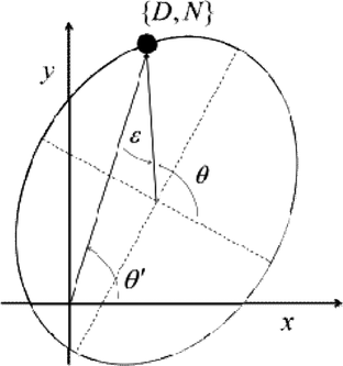
Simply put, the N and D terms must not have any offset, the amplitudes must be equal and the phase must be in quadrature. Associating the {D, N} values with {x, y} coordinate pairs, the conditions for error free phase calculation are seen to be the requirements that all {D, N} coordinate pairs fall on a circle centered at the origin, with amplitude r = ax = ay. In general, however, due to unavoidable errors in the phase calculation process, all {D, N} coordinate pairs will fall on an ellipse centered at {xo, yo}. The error in the phase calculation is equal to the difference between the parameterizing angle, θ, and the coordinate angle, θ′. The relationship between the parameterizing angle and the coordinate angle for a general ellipse is shown in Figure .
Figure 1 General ellipse plot showing the parametric angle, θ, the coordinate angle, θ′, and the difference angle, ϵ =θ′–θ, for a given point {D, N}.
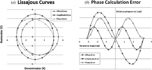
The parameter angle is always equal to the coordinate angle in a circle centered at the origin; this is not the case for a non-centered circle or an ellipse, resulting in the well known single and double frequency print through errors. Lissajous curves are created by plotting the {D, N} coordinate pairs as defined in Equations 2 and 3. Three different curves were created corresponding to an offset error, and amplitude error, and a phase error. These curves are shown in Figure (a). For each of the curves given in Figure , the difference between the parametric angle, θ, and the coordinate angle, θ′, at each point is plotted in Figure (b). Generally, offset, amplitude and phase errors occur simultaneously, and the phase calculation error will be a non-linear combination of these three error sources.
Figure 2 (a) Lissajous plots associated with offset, amplitude, and phase errors where coordinate points given by parametric Equations 2 and 3. (b) Phase calculation error given by the difference between the coordinate and parametric angle of each point in the curves of Figure 2(a).
The use of Lissajous curves in the analysis of phase shifting interferometry has been discussed by Kinnstaetter et al.,[ Citation 3 ] who utilizes Lissajous figures in the analysis of systematic errors; intensity variation, reference phase errors, vibrations, and nonlinearities of the photo detector. Farrell and Player[ Citation 4 ] utilize ellipse fitting and Lissajous figures to calculate the phase difference between interferograms. The idea of using the calculated bias, offset, and phase shift to correct the measured fringe fields which are then used in standard phase shifting calculations is also presented in their paper.
3. ELLIPSE FITTING AND MEASUREMENT TRANSFORMATION
Ignoring a constant phase offset and setting ϕ = (ϕy–ϕx), Equations 2 and 3 may be written as:
Equations 6 and 7 describe a general ellipse with offset {xo, y0}, and semi-major and minor amplitudes of {ax, ay}. The ellipse orientation angle, α, referenced to the x-axis is given by:
Equations 6 and 7 may be rewritten in the form of a general conic as:
A general conic may be described by the following implicit second order polynomial:
F(x, y) is referred to as the algebraic distance of a given point {x,y} to the given conic. For an ellipse, the following conditions must hold:
There are two primary optimization methods for fitting an ellipse to a set of points, {xi, yi} i = 1 …. N. The first method minimizes the sum of the squares of the distances to the given points and is generally referred to as the “geometric fit.” This method is iterative since it involves solving a non-linear least squares problem.[ Citation 5 ] The second method involves minimizing the square of the algebraic distance, F(x, y). Although less robust to outliers, this approach involves the solution of a linear least squares problem and may be directly solved without iteration. Fitzgibbon et al.[ Citation 6 ] first proposed a direct least squares based ellipse-specific method. Due to the potential for computational instability in this approach, a more stable method has been proposed by Halir and Flusser.[ Citation 7 ] Because of its stability and computational efficiency, the direct least squares fitting method of Halir and Flusser has been chosen for the ellipse fitting step in the phase correction computation.
Once the coefficients, {a, b, c, d, f, g}, of Equation 10 are determined, the parametric coefficients, {x o , y o , a x , a y , α}, may be determined from:
Using the best fit ellipse parameters, the measurement numerator and denominator points are transformed to lie on a circle centered at the origin. In other words, the measured parameters are used to remove the offsets, equalize amplitudes and orthogonalize the N and D terms. The transformation can be broken down into 4 steps as shown below.
| 1. | Remove the offset | ||||
| 2. | Rotate the ellipse to align the major and minor axis with x-y axis. | ||||
| 3. | Scale the Numerator values to circularize the data. | ||||
| 4. | Rotate the data back to its original angle. | ||||
These four steps can be represented in matrix form as shown in Equation 17.
4. MEASUREMENT PROCESS
In order to explain the measurement procedure a simplified example will be presented. Once the general idea is cemented a more detailed discussion of alternative approaches, constraints, and limitations will be discussed.
Let's say we have an interferometer that on each measurement returns two interferograms, one phase shifted approximately 90 degrees with respect to the other. The first interferogram in this pair will be designated D(θ), the second N(θ). Using this interferometer we take a series of six measurements , where a phase offset
is introduced between each measurement, Figure (a). Choosing one field point (pixel) in the interferogram, all the {D
i, N
i} points are plotted as shown in Figure (b).
Figure 3 Phase measurement process. (a) On each measurement an interferometer returns two interferograms, each phase shifted approximately 90 degrees with respect to the other. A series of six measurements are made where a phase offset is introduced between the measurements. (b) For a single pixel, highlighted red box, all {D, N} pairs are plotted forming an offset ellipse as shown. From these points a best fit ellipse is determined. C. Using the ellipse fit coefficients, all {D, N} pairs are transformed to lie on a circle centered at the origin. The phase at each point is given by the arctangent of the ratio of the Nt to Dt terms. Steps B. and C. are repeated for all points in the field.
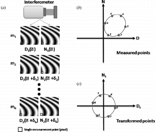
The next step in the measurement process is to find the best fit ellipse to the measured points in order to determine the parametric coefficients, {x o , y o , a x , a y , α}, as given by Equations 13–16. Using these coefficients, the N and D terms are transformed to satisfy conditions given in Equation 5 for an error free phase measurement by using the transformation given in Equation 19, Figure (c). Finally, the phase is determined by taking the arctangent of the ratio of the Nt and D t terms. This process is repeated for all points in the field.
5. MEASUREMENT RESULTS
One advantage of using the pixelated polarization mask phase sensor is that the mechanisms leading to phase-dependent measurement error are static for a given test setup, and thus it is possible to correct for them. The dominant mechanism is polarization mixing between the test and reference beams which is caused by birefringence in both the common and non-common path portions of the interferometer. For a given test setup the polarization mixing is static, although it may not be spatially uniform, thus by using the procedure of Section 3 it is possible to measure and correct for the error on a pixel by pixel basis.
5.1. High Numerical Aperture System Measurement
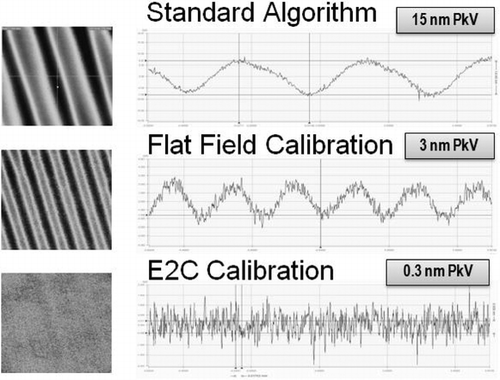
In terms of the discussion of Section 1, polarization mixing primarily results in offset terms in the numerator and denominator of Equations 1 and 2 giving single frequency print-through in the phase measurement. There is also a change in the amplitude balance which results in a lower amplitude double frequency print-through error. Figure shows the results of a single phase measurement on a super smooth flat (surface roughness <0.1 nm RMS). This measurement was taken with an interferometric microscope utilizing 10X, 0.1 NA Linnik objective. As can be seen, the standard measurement procedure results in about 15 nm (λ/50) of single frequency print through. If a flat field calibration procedure is used, which is roughly equivalent to normalizing the offset coefficients, the single frequency print-through is mostly eliminated, but a double frequency component with 3 nm peak-to-valley remains. Application of the full phase correction process of section 3 results in near elimination of both single and double frequency print-through giving a 0.3 nm (λ/2000) peak-to valley error which is below the shot noise limit. Note that these are single shot, not averaged measurements.
Figure 4 Comparison of phase calculation errors for a high numerical aperture system. The top figures show the measurement error, both areal and cross section, when using the standard algorithm. The middle figures provided the resulting error when a flat field correction is applied. The bottom figures show the effect of the ellipse to circle, E2C correction on the measurement error.
5.2. Low Numerical Aperture System with Significant Birefringence Measurement Results
A measurement posing a significant challenge to polarization control was the test of a 0.75-meter diameter convex hyperboloid with a conic constant of −1.660 and radius of curvature of 1.780 meters. This mirror was cryo-tested at 30 K using an aspheric test plate. A 4-D Fizcam2000, a Fizeau interferometer with a 100 mm diameter aperture was used to measure the interferogram generated by the wavefront reflected from the secondary mirror and the aspheric test plate.[ Citation 8 ]
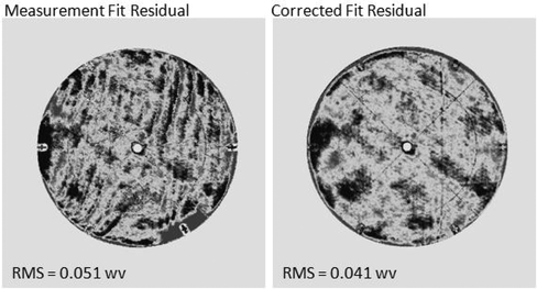
Use of this challenging arrangement resulted in significant polarization aberration in the beams returning to the interferometer. As a result, there was a significant amount of print-through error in the uncorrected phase measurement. Figure shows both the uncorrected and corrected residual phase maps resulting from the removal of a 32 term Zernike fit. As can be seen, print through error is no longer evident and the residual wavefront has gone from 0.051 to 0.041 waves RMS.
6. SUMMARY
Polarization based instantaneous phase measurement systems can suffer from phase dependent errors resulting from systematic polarization aberrations. A general discussion of phase shifting calculation errors has been provided along with a phase error correction methodology. Finally, two examples of phase measurement correction have been shown.
REFERENCES
- Smythe , R. ; Moore , R. Instantaneous phase measuring interferometry . Opt. Eng. 1984 , 23 , 361 – 364 .
- Millerd , J.E. ; Wyant , J.C. Simultaneous phase-shifting Fizeau interferometer. US Patent 7,230,718 , 2007 .
- Kinnstaetter , K. ; Lohmann , A.W. ; Schwider , J. ; Streibl , N. Accuracy of phase shifting interferometry . Appl. Opt. 1988 , 27 , 5082 – 5089 .
- Farrell , C.T. ; Player , M.A. Phase step measurement and variable step algorithms in phase-shifting interferometry . Meas. Sci. Technol. 1992 , 3 , 953 .
- Bookstein , F. Fitting conic sections to scattered data . Comput.Gr.Image Process 1979 , 9 , 56 .
- Fitzgibbon , A.W. ; Pilu , M. ; Fischer , R.B. Direct least squares fitting of ellipses . Proc. 13th International Conference on Pattern Recognition . Vienna, Aug. 25–19, 1996; IEEE: New York, 1996, 253–257.
- Halir , R. ; Flusser , J. Numerically stable direct least squares fitting of ellipses. Technical Report, Dept. Software Eng., Charles Univ., Czech Republic , 2000 .
- Philip Stahl , H. ; Alongi, C.; Arneson, A.; Bernier, R.; Brown, B.; Chaney, D.; Cole, G.; Daniel, J.; Dettmann, L.; Eng, R.; Gallagher, B.; Garfield, R.; Hadaway, J.; Johnson, P.; Lee, A.; Leviton, D.; Magruder, A.; Messerly, M.; Patel, A.; Reardon, P.; Schwenker, J.; Seilonen, M.; Smith, K.; Smith, W.S. Survey of interferometric techniques used to test JWST optical components . Proc. SPIE 7790, Interferometry XV: Techniques and Analysis 2010 , 779002 .

