
Abstract
In this article an approach to a mobile 3-D handheld scanner with additional sensory information is proposed. It fully automatically builds a multi-view 3-D scan. Conventionally complex post processing or expensive position trackers are used to realize such a process. Therefore a combination of a visual and inertial motion tracking system is developed to deal with the position tracking. Both sensors are integrated into the 3-D scanner and their data are fused for robustness during swift scanner movements and for long term stability. This article presents an overview over the system architecture, the navigation process, surface registration aspects, and measurement results.
NOMENCLATURE
| BA | = |
Bundle Adjustment |
| BRISK | = |
Binary Robust Invariant Scalable Keypoints |
| EKF | = |
Extended Kalman Filter |
| FPGA | = |
Field Programmable Gate Array |
| HDR | = |
High Dynamic Range |
| ICP | = |
Iterative Closest Point |
| IMU | = |
Inertial Measurement Unit |
| MPU | = |
Main Processing Unit |
| PTAM | = |
Parallel Tracking an Mapping |
| SLAM | = |
Simultaneous Localization and Mapping |
1. INTRODUCTION
Fringe projection based on portable 3-D scanners with low measurement uncertainty is ideally suited for capturing the 3-D shape of objects in their natural environment. Battery powered, compact scanning devices without other stationary equipment, provide scanning opportunities in-situ at the customer, at a museum or directly at excavation sites. Fringe projection[ Citation 1 ] allows a dense, full-frame 3-D surface to be created from a single viewpoint. Multiple viewpoints are usually required to measure an entire object. This results into complex manual post processing for building a complete 3-D model from several overlapping scans covering the object surface. Alternatively, expensive or complex additional hardware (like infrared or magnetic trackers) are required.
The increased availability and usability of handheld optical 3-D scanning devices as well as the maturing 3-D printing options caused an increased interest in 3-D scanners in general. This applies in particular to the lower end of the 3-D scanner spectrum. While there are impressive results[ Citation 2 ] from KINECT[ Citation 3 ] type of scanners, which acquire a stream of 3-D images, many metrology applications require higher measurement accuracies than these available solutions.
In[ Citation 4 ] a mobile 3-D scanning system is introduced which combines a stereo camera pair and an inertial measurement unit (IMU). The IMU facilitates the registration during the reconstruction of the 3-D model by providing the orientation of the stereo camera pair and an estimation of the translation of the system between viewpoints. A specific heuristic algorithm for multi-view registration which is based on texture similarities is successfully applied and results as good as the Kinect approach in well textured outdoor environments.
This approach inspired the work reported in this article. The NavOScan project,[ Citation 5 ] funded by the European Union's Seventh Framework Programme, led to an add-on navigation unit for conventional, structured light projection based 3-D scanners. This includes fringe projection scanners that are able to provide millions of 3-D point measurements (at low measurement uncertainty) per single acquisition. By extending the 3-D scanning pipeline by automatic scan alignment based on robust sensor pose estimation and 3-D data matching, an easy to use 3-D scanning experience can be realized.
Conventionally, online multi-view 3-D registration has been done using tracking devices, markers, or rapid registration with large overlap. Tracking devices like infrared, optical, magnetic or ultrasonic trackers usually require external, stationery monitoring of the movement of the 3-D scanner. Registration using actively attached markers on the object or features extracted out of the measurement scene itself rely on the visibility and proper correspondence identification of the markers. Marker attachment in most cases is not desired. Typical measurement objects with homogeneous texture cause difficulties in finding good features to track for accurate sensor pose estimation. Visual and inertial sensors are used for pose estimation to overcome the problem of hardware costs and external references.
Although the topic of visual inertial pose-estimation is studied extensively, applications beyond mobile robotics[ Citation 6 ] and large scale motion tracking for mobile platforms[ Citation 7 ] are rare due to a leak of measurement accuracy and reliability over time. The impressive work of[ Citation 8 ] shows the implementation of an extended Kalman filter for the fusion of visual and inertial states. Both IMU and camera state estimation are handled as “black boxes” and can operate independently. The approach of[ Citation 6 ] uses a key frame based visual motion estimation for car motion estimation. They use a stereo camera pair and an IMU. The states are all calculated within one optimization problem at which the position of visual landmarks, biases and motion state are all refined to an optimum. Li and Mourikis[ Citation 9 ] focused on the problem of visual inertial odometry in an unknown environment. Hereby states are estimated in an extended Kalman filter (EKF) framework and states of feature measurements are neglected. The result shows better accuracy, consistency, and computational efficiency than the simultaneous localization and mapping (SLAM) formulation of the EKF due to correct observability properties of the system model and online system calibration. Nevertheless recent studies promise the capability of providing reliable and robust motion estimation in an unknown environment for the application of 3-D scanning.
2. OPTICAL AND INERTIAL SENSOR POSE ESTIMATION
Our approach is the integration of a visual-inertial measurement unit (see Figure ), which can measure the position and the orientation of the 3-D scanner with a certain measurement accuracy and robustness especially in difficult and low textured scenarios like typical industrial applications. It refrains from using external stationary equipment. Instead, it constantly estimates the current sensor pose by combining data from a high-definition inertial measurement unit (IMU) and a high dynamic range (HDR) imaging sensor with wide-angle optics. The IMU provides accurate motion estimates during fast scanner movement, whereas the imaging sensor maintains the accuracy of the estimated pose over an extended scanning sequence. The complementary measurement characteristic of both sensors promises to cover a wide dynamic range of motion due to sensor fusion methods and provides stable and accurate pose estimation to a software module for online 3-D data registration.
Figure 1 Handling of the NavOScan navigation unit prototype (mounted on the Fraunhofer IOF “kolibri CORDLESS” 3-D scanner).
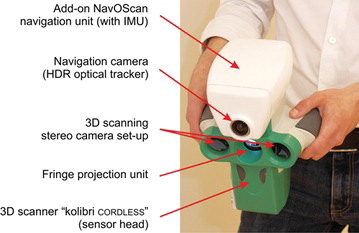
The rationale behind the NavOScan approach is to upgrade a conventional high resolution 3-D scanner with means for automatic multi-view registration. The navigation unit provides stable and accurate pose estimation for online 3-D data registration in a software module. The handheld 3-D scanner “kolibri CORDLESS”,[ Citation 10 ] developed by Fraunhofer IOF, was chosen with the best potential for reference platform creation. In the next section, an overview of the navigation approach as well as aspects about the inertial and visual navigation process is given, while Section three presents the integration of the data into the 3-D scanning process.
2.1.1. Iterative loosely-coupled sensor data fusion
In our approach we focus on the constant availability of the pose information instead of achieving the best measurement accuracy. This means that sensor error and outliers should not cause loss of track. Therefore the inertial and the camera based pose estimation work independently and are fused in an iterative optimization process using a number of pose states and its covariance from each pose estimator. In addition to this we included an optional motion state constraint which is generated by the 3-D Scanner. It is available after the pre-registration successfully aligned a surface scan at a certain time step. The obtained pose information is then included into the optimization process. With this, failures of sensor information like visual occlusions in front of the camera or erroneous inertial pose estimations are acceptable to a certain degree, if one estimator is still providing a valid pose. The presented method is based on the GraphSLAM approach[ Citation 11 , Citation 12 ] and can be adapted to a visual inertial based GraphSLAM estimation.[ Citation 13 ] In this method the optimization tries to find out the most likely state in a specific period of time. The full navigation platform state at time step t is:
The individual constraint terms
F
k
of the sensors are represented in Equation (Equation3), where
x
k
is the calculated state for each sensor k, is the optimal state and
C
k
is the covariance matrix of the sensor states, the index i represents the IMU, c the camera and s the 3-D scanner. This enables different sensor update frequencies and the consideration of pose information from the past. As shown in Figure , the estimated pose is looped back to the visual and inertial state estimator to update the sensor internal states.
Figure 2 Sensor fusion architecture for the fusion of visual inertial sensor data including other sources.
2.1.2. Inertial navigation
The design of the strap-down inertial pose estimation is based on a typical extended Kalman filter (EKF).[ Citation 14 ] It estimates the six degree of freedom pose, including the velocity and the bias of the gyro and the acceleration sensor. The state vector in the IMU coordinate frame i is defined as:
The transformation between the IMU and the world coordinate frame e is defined with
C
ei
, the matrix Φ(ω) is the small angle approximation of the measured rotational velocity ω[
Citation
15
],
a
is the acceleration vector. The measurement update of the Kalman filter is adapted to the dynamic behaviour of the system. We defined two levels of static behaviour: The first is the situation at which we measure no dynamic motion by analysing at the standard derivation and the frequency spectrum of the acceleration and the gyroscope. With this it is possible to correct the orientation and the gyro biases by the acceleration measurement. The yaw-angle θ. is not observable but with the assumption it can be set constant to avoid drift behaviour during the static phase. Similar to this we can observe the velocity state with the assumption that the velocity vector in the body coordinate frame of the IMU
. The support vector
with the noise ϵ for the Kalman filter measurement update is calculated by:
The second static level is used to limit the system model dynamic. Therefore in the presence of low acceleration dynamic, the velocity and the position dynamic are set to zero. It prevents drift caused by acceleration bias errors. During a dynamic motion phase we have no possibility to observe the states without external information. As described in[
Citation
16
] we can assume how the error of the orientation estimation could grow due to the correction of the orientation and the gyro bias by the acceleration measurement in the following static phase. Accordingly we use the orientation error between the last dynamic time step and the corrected orientation to recalculate the system model in the dynamic phase during the time interval [t
start
, t
end
]. with a linear error model which is approximated using the first Taylor approximation in the quaternion space:
Next to this an additional constraint is available from the estimated motion vector of the visual inertial sensor fusion. On the basis of this observation we can correct the position and the quaternion vector of the IMU state in static and dynamic conditions.
2.1.3. Visual navigation
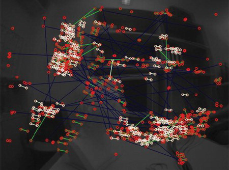
The visual navigation is based on monocular key frame based SLAM, the so called PTAM approach.[ Citation 17 ] In PTAM, bundle adjustment (BA) is used instead of the typical filtering approach. PTAM builds a map of the environment by triangulating objects that are observed as matched features in images taken from significantly different vantage points. These images are called key frames. At the same time it uses this map of 3-D features to estimate the current camera pose by finding the locations of these 3-D features in the current image. This is the normal PTAM operation when it is in the tracking state. Several details have been adjusted or improved to meet the requirements. The approach is adapted to improve the reliability of the motion information in most conditions: a reliable scene initialization with motion information from the overall sensor fusion; Map initialization with multiple key frames; Usage of rotationally invariant BRISK binary descriptors[ Citation 6 ] for fast frame-to-frame matching (see Figure ); bundle adjustment for the triangulation process and the usage of HDR imaging sensor. The camera pose estimation uses the initial pose guess from the inertial pose estimator to speed up the feature correlation and to give an initial guess for the camera pose calculation. It finds the best match between the matched features and the 3-D points in the generated maps. We improved the quality of the map making by using corrected pose estimations from the visual inertial sensor fusion process. The triangulation process uses a bundle of several features sets with its corresponding camera pose. So consequently we can correct all poses of the triangulation with the corrected pose. The HDR sensor has a logarithmic transfer function and a dynamic range of about 120 dB. This allows the simultaneous capture of dark and light background areas without oversaturation at a fixed exposure setting. Consequently, the image features do not change in appearance as light sources or sunlit areas enter or exit the field of view. All in all the imaging system is designed to maintain the integrity of the visual tracking in uncontrolled lighting conditions.
Figure 3 Detected natural scene features (circles) and appearance-based feature correspondences (line segments) between a key frame and the current view during map initialization. Shown in white are the correspondences automatically selected for inclusion in the initial 3-D map based on geometric constraints.
3. INTEGRATION OF THE NAVIGATION UNIT INTO THE 3-D SCANNER
The software framework of the current generation “kolibri CORDLESS” 3-D scanner, whose predecessor was first presented by[ Citation 10 ] was extended to make use of the NavOScan navigation unit (see Figure ). With its small (about 220 mm × 190 mm × 190 mm) and lightweight (1.6 kg) sensor head it is predestined for handheld operation. This is especially the case due to its short 3-D scan acquisition time of ≥300 k data points in less than 250 ms with low measurement uncertainty of ≤100 µm (in surface normal direction). The scanner uses a stereo camera setup and a fringe projection based structured light approach[ Citation 18 ] for 3-D data measurement by triangulation between corresponding points.
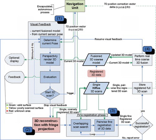
Figure 4 The navigation data is used to provide the user with visual feedback (1). After the user starts a new scan (2) the scanner acquires a pint cloud and to coarsely register the current 3-D scan. Subsequently, the current scan is fine registered into the previous scans (3). Finally a new global 3-D model can be calculated for user feedback purposes (4).
3.1. Multiple View Registration
The pose from the navigation unit is used as start solution to the Iterative Closest Point (ICP) algorithm,[ Citation 19 ] which is known to work well for registration of 3-D point clouds of overlapping parts of a rigid object. Several adaptions to the ICP algorithm due to the intended handheld usage scenario are necessary: Outlier and constraint handling, multi patch registration and high speed implementation. While not actively performing a scan, the system supports the user by providing visual feedback (1) (see Figure ) for determining the next best view. After the user starts a new scan (2), the scanner acquires a dense point cloud. By using the current 3-D scan's sensor pose estimation from the navigation unit, the resulting 3-D scan is already coarsely registered. During fine registration (3) the current scan will be sufficiently aligned for coarse 3-D model creation (4) using pairwise ICP registration.
Upon scan completion, the fine registered 3-D point cloud can be exported and post processed according to the intended usage scenario. A simple, automatic global optimization over all 3-D scans taken is usually required to provide a high quality 3-D model.
4. REAL-TIME USER GUIDANCE
The result of the multi-view registration is presented to the user as a 3-D rendering on an (optionally) attached display. To provide the user with direct feedback, the state of the last 3-D registration is shown via colour codes directly projected into the measurement volume by the digital projector of the 3-D scanner. A green frame around the projected pattern indicates a successful registration and the ability to proceed with the next scan, whereas a yellow frame indicates an ongoing calculation. A red frame signals a failed registration, which could originate from the navigation unit loosing track or the registration module fail because of insufficient overlap between the individual views. The user can then chose to repeat the corresponding scan or proceed to another view pose.
More advanced user guidance possibilities could also be easily implemented using the navigation unit's sensor pose estimation, if an optional display is attached. The currently completed 3-D model of the object to be scanned can be visualized from the scanner's perspective. This allows the user to choose a new viewpoint for optimal gap filling.
5. MEASUREMENTS RESULTS
5.1. Sensor System for the Measurement Trails
Figure shows the navigation units hardware architecture. With the chosen Epson S4E5A0A0 IMU[ Citation 20 ] it is possible to observe position and orientation of the system with sufficient accuracy. Additionally, we propose a visual inertial system with a high dynamic range (HDR) sensor. We chose the New Imaging Technologies (NIT) NSC1001 global shutter CMOS HDR imaging sensor (1/3 inch) with 640 × 480 pixel resolution.[ Citation 21 ] The navigation unit's embedded controller is a Xilinx Spartan-6 FPGA. The main purpose of using an FPGA is to reduce the amount of data needed to be processed by the main processing unit (MPU). This is done by the FPGA taking care of both data acquisition and data processing tasks.
Figure 5 The sensor network's hardware is built around a FPGA, which communicates the reprocessed sensor data to the 3-D scanner's main processing unit via a GigE interface.
5.2. Motion Measurement with the Visual Inertial Navigation System
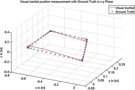
Figure and Figure show the results of the visual inertial measurement with a rectangular motion and a loop closure. The trail length is approximately 1500 mm. The error after the loop closure measures 16 mm RMS for the position and 0.2° RMS for the orientation measurement. This error is still acceptable to forward the information to the 3-D scanner registration process. We generated the results without the usage of the 3-D scanner position correction value from the pre-registration process.
Figure 6 Visual inertial position measurement with loop-closure.
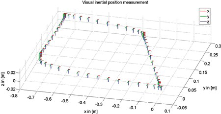
Figure 7 Visual inertial position measurement in comparison to ground truth which is generated by an infrared motion capture system.
5.3. 3-D Scanning
Typical application areas of portable, handheld 3-D scanners are industrial manufacturing inspection, cultural heritage documentation, and forensic documentation. Two typical measurement objects for the first and second case are shown in Figure and Figure . The measurements are performed under laboratory conditions using the current work-in-progress hardware and software state of navigation unit.
Figure 8 Different views of the 3-D scanning results of the “Schiller” bust (plaster bust, approximately 220 mm × 210 mm × 290 mm, 17 views).
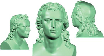
Figure 9 From left to right: photo, 3-D scan result and 3-D comparison to the ground truth data of the assembled “sand core” model (approximately 410 mm × 200 mm × 80 mm, 12 views).
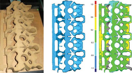
The “sand core” model represents a challenging measurement object due to its repetitive surface structure. 3-D comparison to the ground truth data shows a standard deviation of the 3-D error of 0.2 mm. The 3-D error is defined as the distance in normal direction of the measured 3-D points to the surface of the CAD model. This error can be decreased even further by improving the accuracy of the sensor pose estimation. The color representation of Figure shows the 3-D error with the unit in millimeter.
The 3-D scan of the bust of the 18th century German poet F. Schiller demonstrate the NavOScan scanning system's ability for 360° measurements and successful registration of even highly detailed, ambiguous parts (hair) into a complete 3-D model.
6. CONCLUSION
The NavOScan approach—the development of a navigation unit to automate the registration of multiple 3-D scans of an object into a global 3-D model—has been shown to be a viable solution to overcome the time consuming manual registration step conventionally needed. At the same time the integration into an existing 3-D scanning solution has been demonstrated. The developed handheld 3-D scanner can be used to easily and accurately digitize small to medium sized objects. The navigation unit uses motion data from an IMU and a camera state estimator which are fused based on a GraphSLAM framework to realize different sensor frequencies, a modular sensor system and an additional motion constraint by the 3-D scanner pre-registration result. Adaption of visual and inertial motion sensing technics are done to provide robust position and orientation information in the required range of motion. The reported navigation measurement result shows the potential of a visual inertial sensor approach to enable an automated registration process for 3-D handheld scanners. Further work includes the improvement of the sensor pose estimation's robustness as well as accuracy to minimize erroneous registrations of 3-D scans.
ACKNOWLEDGMENTS
The authors would like to thank Carlos Mendoza from Innovation Center Iceland for his engineering support received in this project.
Notes
Color versions of one or more of the figures in the article can be found online at www.tandfonline.com/uopt.
REFERENCES
- Gorthi , S.S. ; Rastogi , P. Fringe projection techniques: Whither we are? Opt. Laser Eng. 2010 , 48 , 133 – 40 .
- Newcombe , R.A. ; Izadi , S. ; Hilliges , O. ; Molyneaux , D. ; Kim , D. ; Davison , A.J. ; Kohi , P. ; Shotton , J. ; Hodges , S. ; Fitzgibbon , A. KinectFusion: Real-time dense surface mapping and tracking. In Mixed and Augmented Reality (ISMAR), 2011 10th IEEE International Symposium, Basel, Nov 26–29, 2011; IEEE, Washington, DC, 127–136.
- Microsoft Corporation . 2014 . Kinect. https://www.microsoft.com/en-us/kinectforwindows. (accessed June 5, 2014) .
- Byczkowski , T. ; Lang , J. A stereo-based system with inertial navigation for outdoor 3d scanning. Computer and Robot Vision, 2009. CRV ‘09. Canadian Conference, Kelowna, British Columbia, Canada, May 25–27, 2009; IEEE, USA, 221–28 .
- Kleiner , B. NavOScan project homepage. 2014. http://www.navoscan.eu (accessed June 5, 2014) .
- Leutenegger , S. ; Furgale , P. ; Rabaud , V. ; Chli , M. ; Konolige , K. ; Siegwart , R. Keyframe-based visual-inertial SLAM using nonlinear optimization. In Proceedings of Robotics: Science and Systems, Berlin, Germany, June 24–28, 2013; Robotics Science and Systems online proceedings .
- Li , M. ; Byung , H.K. ; Mourikis , A.I. Real-time motion tracking on a cellphone using inertial sensing and a rolling-shutter camera. In Robotics and Automation (ICRA), 2013 IEEE International Conference, Karlsruhe, May 6–10, 2013; IEEE, USA, 2013, 4712–4719 .
- Weiss , S. ; Siegwart , R. Real-time metric state estimation for modular vision-inertial systems. 2011 IEEE International Conference on Robotics and Automation (ICRA) 2011, 4531–37 .
- Li , M. ; Mourikis , A.I. High-precision, consistent EKF-based visual–inertial odometry . Int. J. Robot. Res. 2013 , 32 , 690 – 711 .
- Munkelt , C. ; Bräuer-Burchardt , C. ; Kühmstedt , P. ; Schmidt , I. ; Notni , G. Cordless hand-held optical 3D sensor . Proc. SPIE 2007 , 6618 .
- Thrun , S. ; Montemerlo , M. The GraphSLAM algorithm with applications to large-scale mapping of urban structures . International Journal on Robotics Research 2005 , 25 , 403 – 30 .
- Grisetti , G. ; Kümmerle , R. ; Stachniss , C. ; Burgard , W.A tutorial on graph-based SLAM. Intelligent Transportation Systems Magazine, IEEE 2010 , 2 , 31 – 43 .
- Corominas Murtra , A. ; Tur , J.M.M. IMU and cable encoder data fusion for in-pipe mobile robot localization. In Technologies for Practical Robot Applications (TePRA), 2013 IEEE International Conference, Woburn, MA, USA, April 22–23, 2013; IEEE, USA, 1–6 .
- Wendel , J. Integrierte Navigationssysteme: Sensordatenfusion, GPS und inertiale Navigation. , 2nd revised edition . Oldenbourg Wissenschaftsverlag : München , 2011 .
- Kuipers , J.B. Quaternions and Rotation Sequences: A Primer with Applications to Orbits, Aerospace, and Virtual Reality . Princeton University Press : Princeton , N.J. , 1999 .
- Wang , J.S. ; Hsu , Y.L. ; Jiun , N.L. An inertial-measurement-unit-based pen with a trajectory reconstruction algorithm and its applications . Industrial Electronics, IEEE Transactions on 2010 , 57 , 3508 – 21 .
- Klein , G. ; Murray , D. Parallel tracking and mapping for small ar workspaces. 2007. ISMAR 2007. 6th IEEE and ACM International Symposium on Mixed and Augmented Reality 2007, 225–34 .
- Kühmstedt , P. ; Munkelt , C. ; Heinze , M. ; Bräuer-Burchardt , C. ; Notni , G. 3D shape measurement with phase correlation based fringe projection. In Society of Photo-Optical Instrumentation Engineers (SPIE) Conference Series, Munich, Germany, June 18, 2007, SPIE, USA, 6616 .
- Besl , P.J. ; McKay , H.D. A method for registration of 3-D shapes . IEEE Trans. Pattern Anal. Machine Intell. 1992 , 14 , 239 – 56 .
- Seico Epson Corporation . 2012 . S4E5A0A0A1 IMU specification. http://www.eea.epson.com/portal/page/portal/ver-1/home/products/Sensing_Solutions/documents/IMU%20G1%20Brief%20Specification.pdf (accessed June 5, 2014) .
- New Imaging Technologies . 2014 . Native WDR CMOS sensors. http://www.new-imaging-technologies.com/native-wdr-cmos-sensors.html (accessed June 6, 2014) .
- Color versions of one or more of the figures in the article can be found online at www.tandfonline.com/uopt.