
Abstract
Optical Diffraction Tomography is a technique for retrieving a 3-dimensional refractive index distribution from phase objects without destroying the structure of the samples. In the article we discuss the selection and implementation of full and limited angle version of tomographic reconstruction processes together with the analysis of different methods for gathering projections. We present two efficient implementations of full and limited angle tomographic systems including total processing paths and providing the examplary results of 3-D refractive index determination measurements of biological samples.
NOMENCLATURE
| DHM | = |
Digital Holographic Microscope |
| SIDHM | = |
self-interference Digital Holographic Microscope |
| ODT | = |
Optical Diffraction Tomography |
| FBPJ | = |
Filtered Backprojection |
| FBPP | = |
Filtered Backpropagation |
| HOT | = |
Holographic Optical Tweezers |
| CT | = |
Computed Tomography |
| FDTD | = |
Finite Difference Time Domain |
| SART | = |
Simultaneous Algebraic Reconstruction Technique |
| DRA | = |
Data Replenishment algorithm |
| TVM | = |
Total Variation minimization |
| FC | = |
fiber capillary |
| PD | = |
Petri dish |
| MRM | = |
motorized rotary mirror |
| λ | = |
wavelength |
| n rec | = |
reconstructed refractive index |
| n ob | = |
model's refractive index |
| rec.error | = |
refractive index reconstruction error |
| Δn | = |
refractive index variation |
| Φ | = |
object's diameter |
1. INTRODUCTION
Several hot biomedical topics including: label-free analysis of living cells and tissues, characterization of physical processes in cellular biophysics, extended studies in vascular and tumor biology, as well as recognition and monitoring of bacteria colonies require accurate three-dimensional (3-D) reconstruction of a biological, micro-object structure. Digital holographic microscopy (DHM), when applied to semitransparent samples such as living cells, provides accurate measurements of phase shift resulting from a mean refractive index accumulated over the cellular thickness.[ Citation1-5 ] However, a single shot holography is inadequate to provide true 3-D reconstruction of a cell structure. On the other hand it has been proved by many groups that the solution can be provided by combining digital holography with tomographic techniques. The resultant method, often referred to as optical diffraction tomography (ODT),[ Citation6-9 ] requires capturing multiple complex object fields for different illumination directions with respect to the sample and later tomographic reconstructing of a three-dimensional distribution of refractive index. The accuracy of a 3-D reconstruction depends on several features of an object and data gathering system. An object may be characterized by different values and gradients of refractive index, which determine the influence of diffractive and refractive effects on a beam passing through an object and in consequence the choice of one of the standard tomographic algorithms (e.g., filtered backprojection[ Citation 10 ] and filtered backpropagation[ Citation 11 ]). The projections are obtained through varying an illumination direction[ Citation 8 ] or rotating a specimen.[ Citation 6 , Citation 7 ] They may be captured in the full (180° or 360°) angle (as required for standard tomographic procedures) or in a limited angle.
In the article we discuss several problems connected with a choice and implementation of full and limited angle tomographic reconstruction processes. Section 2 presents the description of the methods used for gathering projections in tomography. In Section 3 we compare the accuracy of two most widely used tomographic reconstruction algorithms: filtered backprojection (FBPJ) and filtered backpropagation (FBPP). We show that FBPP algorithm with first order Rytov approximation delivers a more precise tomographic reconstruction than FBPJ. However, for small gradients of refractive index, which is a case of analyzed biological objects, the error calculated with both methods is very similar so FBPP with the first order Rytov approximation can be replaced by Hybrid FBPJ. In Section 4 we describe possible solutions for limited angle case, based on the type of measured object. In Section 5 we demonstrate detailed description of the measurement setup. In Section 6 we present the description of the processing paths, whereas in Section 7 we implement these paths and present the experimental results of 3-D refractive index determination.
2. PROBLEMS AND SOLUTIONS FOR GATHERING TOMOGRAPHIC PROJECTIONS
In optical diffraction tomography multiple measurements of optical field transmitted through the sample for various illumination directions are used in order to obtain a 3-D reconstruction of refractive index distribution. This requirement of multiple angle measurements appears to be the greatest challenge in this technique. Different solutions lead to different problems and results in terms of the measurement system architecture as well as achievable resolution and available amount of data.
There are two general methods used to obtain multiple holographic projections of an object. The first approach relies on capturing holographic projections during rotation of an object.[ Citation 6 , Citation12-14 ] In such case the greatest problem is the means to provide an appropriate rotation system. This may be realized using a micropipette[ Citation 12 ] utilized to hold the object. Unfortunately, such solution most certainly perturbs the object and is not advisable for delicate specimens, like e.g., living cells. Another means to rotate a sample is to place it inside a hollow-core optical fiber.[ Citation 6 , Citation 13 , Citation 14 ] However, this solution has also some disadvantages. Once the sample is placed inside the cuvette it is not always feasible to prevent it from adhering to its inner walls. When biological objects are studied, it is impossible to avoid strong diffraction at the interface of fused silica capillary and cell culture medium, thus the sample should preferably be placed in the very center of the hollow fiber. Also, although the fiber is placed in an immersion liquid, it will cause a systematic phase error. Furthermore, the viscosity of the medium inside the fiber capillary is important in order to prevent the measured objects from tumbling. Another implementation of the object rotation is achievable using Holographic Optical Tweezers (HOT) or its variations. Usually, optical tweezers employ angular momentum of light in order to rotate an object in the object plane (rotation around optical axis).[ Citation 15 ] For tomography purposes, however, it is necessary to deliver rotation around an axis lying in the object plane. This problem has already been solved with a device named Optical Cell Rotator,[ Citation 16 ] which is based on two counter-propagating laser beams and trapping a cell in a direction perpendicular to the optical axis. Nevertheless, there are still two promising applications of HOT that might be adapted to tomography. Tomography could be either using an oscillating optical tweezers in order to rotate rod-shaped cells[ Citation 17 ] or providing a 3-D rotation of a cell using two traps per object.[ Citation 18 , Citation 19 ]
The second approach is to deliver multiple projections of an object is based on altering the angle of illumination or/and observation rather than influencing the sample. As a matter of fact, this also may be realized in different manners. Despite the possibility to rotate the optical setup in a similar way to X-Ray CT (Computed Tomography) medical scanners, where both a source and detector are rotating, such concept has not yet been reported. Instead, the optical system and the detector is stationary, while the illumination beam incidence angle is altered.[ Citation 7 , Citation 8 , Citation20-27 ] In this case it is a motorized tilting mirror that usually alters the projection angle.[ Citation 7 , Citation 8 , Citation20-24 ] Also, it has been reported that the multiple projections may be gathered using a rotary optical prism, deflecting the beam.[ Citation 25 ] Finally, it is possible to create multiple light sources instead.[ Citation 26 , Citation 27 ] Nevertheless, all of the reported solutions lead to a limited-data problem, because when the optical detection system and the object is stationary it is impossible to overcome the limit of maximum angle of observation posed by the limited numerical aperture of the setup.
3. COMPARISON OF RECONSTRUCTION ALGORITHMS FOR FULL ANGLE PROJECTIONS
The tomographic reconstruction is usually performed with one of the two methods: filtered backprojection (FBPJ)[ Citation 10 ] or filtered backpropagation (FBPP)[ Citation 11 ]tomographic algorithms. The FBPJ algorithm uses light propagation model of Thin Element Approximation, where light is propagated along straight lines. This assumption disregards diffraction. However, it was shown that the algorithm is able to provide an accurate reconstruction for the object regions, which are well focused. This feature is used by Hybrid FBPJ algorithm, in which phase distributions that are focused in the object center, are used for reconstructions.[ Citation 9 , Citation 28 ] The FBPP algorithm is formulated according to the theory of diffraction, however it usually uses an approximated model of the first order Rytov approximation. Therefore, it should deliver a more precise tomographic reconstruction than FBPJ. In the current work[ Citation 29 ] we have compared accuracy of both algorithms for off-axis reconstructions, i.e., for cases where object features are located far from the object center. The study confirmed that FBPP algorithm based on the Rytov approximation partially accounts for diffraction effects therefore; in general case it is able to provide better off-axis results than FBPJ.
It is recognized that ODT provides accurate reconstruction of the objects having small deviations of refractive index. In this section we compare accuracy of the reconstructions obtained with FBPP and hybrid FBPJ for objects with features with high gradient of refractive index. It has been shown[ Citation 28 ] that performance of both algorithms is similar for objects with larger deviation of refractive index. However, the numerical study was performed using approximated simulation method,[ Citation 30 ] which is accurate for objects with small deviation of refractive index. Therefore, in this section, we perform simulations using more accurate Finite Difference Time Domain method (FDTD), which directly solves Maxwell's equations.[ Citation 31 ]
To study the errors of refractive index reconstruction, the numerical tomographic experiments for axisymmetric cylindrical objects of step-index profile were performed using FDTD and angular spectrum propagation method.[ Citation 32 ] Three dimensions of the object 10λ, 20λ, 50λ (λ = 0.5 µm) and various steps of refractive index in a range from 0 to 0.1 were considered. Then, based on simulation results, the tomographic reconstructions were performed using Hybrid FBPJ and FBPP.
The reconstructed refractive index distributions nrec were compared quantitatively with the assumed object model nob via equation:
Figure 1 The errors of tomographic reconstruction using Hybrid FBPJ and FBPP for fiber having step-index profile.
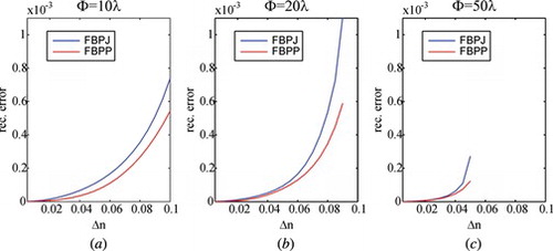
The numerical experiment shows that there is a substantial difference of the errors obtained by using FBPJ and FBPP tomographic reconstruction algorithms, which corrects the conclusion of the publication.[ Citation 13 ] However, for small gradients of refractive index (Δn < 0.03) the error calculated with both methods is very similar so FBPP with the first order Rytov approximation can be replaced with Hybrid FBPJ. For larger values of Δn the error increases for Hybrid FBPJ so this approach should be used with caution.
4. TOMOGRAPHIC RECONSTRUCTION FOR LIMITED ANGLE PROJECTIONS
Biological objects often require special growing conditions, e.g., in the Petri dish. The structure of the Petri dish makes it impossible to capture projections of a sample within a 180° range. This is a case of limited angle tomography. Another example is a need for a video-rate tomography[ Citation 33 ] where the limited angular range allows for a fast measurement. In these cases the tomographic procedures described above have to be modified in order to deal with lack of initial data. In the Radon domain a limited angular range can be considered as a partially empty sinogram. Because the Radon domain is associated with the Fourier domain both in an x-ray tomography[ Citation 34 ] and diffraction tomography,[ Citation 11 ] that lack of data is also present in the spectrum of the reconstruction.[ Citation 35 ] These constraints impose the necessity to implement different algorithms than FBPJ or FBPP. Iterative methods, like iterative constraint algorithm[ Citation 36 ] or Simultaneous Algebraic Reconstruction Technique (SART),[ Citation 37 ] may be applied to improve quality of the reconstruction. However, without additional constraints, these methods give big errors in a reconstruction.[ Citation 20 ] The additional constraints depend on the properties of a measurement system and a class of a measured object and include: (1) nonnegativity, when 0 is the smallest possible value in the reconstruction,[ Citation 21 ] (2) smoothness of a distribution of refractive index,[ Citation 38 ] (3) external geometry of an object,[ Citation 39 ] and others.
One class of objects consists of samples with a known external geometry. For example, if a measured sample is a round cell, one may improve the final result in a reconstruction process by creating a mask with the known geometry and by applying that mask in every iteration. One possible way to reconstruct such an object from limited input data is the iterative constraint method, also known as the Data Replenishment algorithm (DRA).[ Citation 36 ] The core of this method is iterative calculation of the Radon and Inverse Radon Transforms. In each step we replenish the sinogram in the known region with the known projections. In the reconstruction domain we apply the a priori information in the form of different masks—here the mask with geometry of a sample.
Another class of objects represents biological and technical samples that are characterized with the piecewise constancy of a refractive index distribution. Optical fibers, optical bridges, microtips, red blood cells etc. belong to that class. Knowledge about this property is a very powerful constraint. In order to account for piecewise constancy one can combine SART algorithm with a Total Variation Minimization (TVM) method.[ Citation 40 ] TVM is a part of Compressed Sensing, which utilizes information about sparseness of some object's parameter in order to solve an underdetermined problem, like limited data tomography. One of the most often used parameters is pixel value distribution. In the case of piecewise constant objects the sparseness can be found in the gradient image of the sample, e.g., the gradient image of the piecewise constant Shepp-Logan phantom has 94% pixels with value 0. TVM aims at maximizing this sparseness or, in other words, at minimizing the Total Variation norm of the image:
In the case of real data, where noise is present, despite the fact that the gradient of the reconstruction has few 0 values, the TVM modifies the image in such a way, that the resultant image is sparse. This is the reason, why the TVM is also used as a noise-reduction filter.
In this article, for limited angle tomography, we will use DRA and SART + TV algorithms (depending on the class of the object).
5. MEASUREMENT SETUPS FOR FULL AND LIMITED ANGLE PROJECTIONS
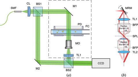
The most versatile measurement setup architecture, used for tomography purposes, is based on Mach-Zehnder interferometer concept.[ Citation 6 , Citation 20 , Citation 24 ] This configuration can be easily modified because an object and reference beam are separated. Thus, it is possible to use either full angle or limited angle module depending on the application. Such case is presented in Figure . In this setup, the Nd:YAG frequency-doubled laser beam (λ = 532 nm) is delivered to the system using a single-mode optical fiber (SMF) and then collimated with a collimator lens (CL). Then, it is split into reference and object beams by a beam splitter (BS1). In the object arm of the system either full angle (dashed line box in Figure (a)) or limited angle (Figure (b)) module may be used in order to provide the scanning system and image the measured sample onto the CCD sensor. The reference arm is used in order to create a spatial carrier fringe pattern in the camera plane by a tilt of a mirror (M2). This enables the application of Fourier transform phase retrieval method.[ Citation 41 ] In the full angle tomography (Figure (a)) the optical setup is stationary. Only the fiber cuvette (FC) is rotated. The orientation as well as frequency of the spatial carrier fringes is constant for every acquired hologram. However, when limited angle tomography module (Figure (b)) is used, the spatial carrier has to be introduced in a specific direction so that only the fringe orientation is affected during tomographic measurement. Otherwise, applying Fourier transform phase retrieval method would be difficult to implement because the spatial carrier frequency would change with every projection direction. The key components that enable gathering a set of projections are fiber capillary (FC) in the Petri Dish (PD) in Figure (a) and motorized rotary mirror (MRM) in Figure (b). Considering the former, FC is usually mounted on a stepper motor or a motorized fiber holder (e.g., Elliot Martock MDE-235[ Citation 14 ]) and FC can be placed inside a PD using syringe needles of size suitable to the FC diameter. In the other case, the MRM determines the performance of the system as the mirror may be mounted on a stepper motor[ Citation 23 ] or a galvanometric mirror (e.g., HS-15, Nutfield Technology[ Citation 24 ]).
Figure 2 Measurement setup for full angle (a) and limited angle tomography module (b). Figure 2(a): SMF—single mode fiber, light source—frequency doubled Nd:YAG laser λ = 532 nm; CL—collimating lens (f’ = 50 mm); BS1, BS2—50:50 Beam splitting cube; M1, M2—mirror; PD—Petri Dish; FC—Fiber capillary; MO—Long working distance 20x microscope objective; TL—Tube lens (f’ = 150 mm); CCD—Charge-Coupled Device camera. Figure 2(b): MRM—Motorized rotary mirror; TL1—tube lens (f’ = 75 mm); BFP—back focal plane; SPL—specimen plane; TL2—tube lens (f’ = 150 mm).
Nevertheless, despite the benefits of Mach-Zehnder configuration, as the basis for our measurement system we selected the self-interference Digital Holographic Microscope (SIDHM),[ Citation 42 ] which is highly insensitive to vibration due to replacing the reference arm with a shearing module realized by a Michelson interferometer (Figure ). The coherent light source used was a λ = 532 nm laser. Imaging was performed by a Zeiss Achromatic microscope objective (Zeiss LD Achroplan 20x/0.4 Korr) with long working distance (10 mm). Digital off-axis holograms were captured using a Basler pia-2400-12 gm camera with pixel size of 3.45 µm. This provided the overall optical resolution of 0.67 µm and 0.18 µm spatial sampling of the object. Numerical evaluation of digital holograms for retrieval of quantitative phase images was performed by spatial phase shifting-based reconstruction algorithm as described in detail by Kemper et al.[ Citation 4 ]
Figure 3 The self-interference Digital Holographic Microscope with the rotary fiber holder setup. WL—white light source, SMF—single mode fiber, CL—condenser lens, BS—beamsplitter, PD—Petri dish, IL—immersion liquid, FC—fiber capillary, MO—microscopic objective, M—mirrors.
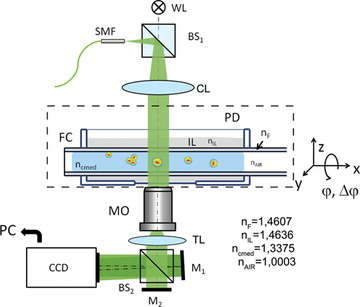
A tomography module added to SIDHM is based on implementation of a hollow optical fiber as a cuvette for a cell or a group of cells. Main feature of this concept is the fact that cells—once placed in a hollow fiber—grow in a similar way as in Petri dish. However, due to cylindrical shape of the capillary, in order to avoid strong diffraction and allow holographic measurements, it is necessary to insert it into immersion liquid as shown in Figure . A standard microscope stage has been replaced with a custom one that consisted of Petri dish support and an Elliot Martock rotary fiber holder. The holder assured high precision of specimen position for each projection acquired as it offers a resolution of less than 0.01°. A cell once inserted in the hollow fiber can be properly placed in the field of view through 3-D manipulation of the fiber. The inner diameter of the fiber capillary was 212 µm and the outer one—300 µm. The refractive index of the fiber capillary was n = 1.46071 at λ = 532 nm. The inner surface of the fiber was treated with 0.5% PVA in order to prevent cells from attaching to the fiber walls.[ Citation 43 ] The fiber was placed inside a Petri dish (iBidi) with immersion liquid of refractive index n = 1.4636 at λ = 532 nm. This assured proper thickness of the cover-glass for microscope objective to work with.
However, it has to be mentioned that insertion of a cylindrical element into an object path of DHM setup results in a severe focusing deformation of the object wave. The aberration is especially strong because the choice of an inner cell culture medium is a result of its biological properties, thus its refractive index cannot be properly matched to the fiber capillary itself and that causes a strong diffraction and refraction effects at its inner wall. In the next Section we are discussing how to correct this systematic error.
6. EXPERIMENTAL DATA ANALYSIS
In Sections 3 and 4 we presented reconstruction algorithms for full and limited angular range of projections. In this section we present the preprocessing procedures that have to be carried out on the projection data before these reconstruction algorithms can be used.
6.1. Tomographic Reconstruction From Full Angle Projections
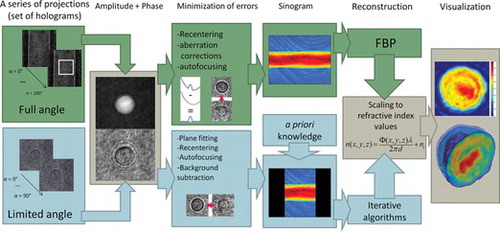
Tomographic reconstruction requires acquiring a set of images corresponding to a series of angular projections of an object. The best reconstructions are obtained if the information is captured in full angle (in the case of complex 3-D objects projections around two axes are required). In our case 180 projections were captured with 1° angle of rotation between sequential measurements. Each hologram, captured with self-interference DHM, has been refocused[ Citation 42 ] in order to obtain a fully focused image of a cell and to ensure that in the best case the whole cell is within microscope objective's depth of field. Then, an integrated phase of each projection has been reconstructed[ Citation 4 ], as shown in Figure .
Figure 4 The flow chart of the tomographic procedure from capture to 3-D refractive index determination.
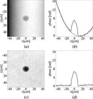
As we already mentioned, because of the capillary geometry, there is a strong aberration present in the reconstructed phase. One of the most widely used approaches of the phase correction is direct subtraction of the phase aberration from the original object phase distribution. As it has already been demonstrated,[ Citation 44 ] this approach allows for an effective compensation of the aberration when the specimen is located within the central area of the capillary. In the phase subtraction approach a shape of the wave aberration can be determined by carrying out a computational simulation of wave transition through a digital model of the existing capillary or by performing an additional reference measurement for the empty vessel. However, in this work we employ other approach, in which estimation of the phase aberration is performed using the specimen's hologram itself. In this approach, after masking the sample area in the original object phase image, the polynomial fitting procedure is applied to determine the exact shape of the phase aberration. Afterwards, the fitted surface is subtracted from the original projection. Illustration of the phase correction process on the example of a hologram of a living human leukemia cell is presented in Figure . Figure (a) shows the original object phase distribution with a clearly visible cylindrical phase aberration associated with the fiber capillary. In Figure (b) we show cross-section of the aberrated phase (solid blue line) and the fitted aberration profile (dashed red line). The results of the correction are presented in Figures (c) and (d).
Figure 5 The correction of phase aberration associated with the fiber capillary: (a) original phase distribution; (b) cross-section of the phase distribution (solid line) and of the fitted aberration profile (dashed line); (c) and (d) the correction results.
The phases after correction for radial run-out (recentering of an object) were used as an input for tomographic algorithm. Tomographic reconstruction has been performed using Filtered Back Projection method.[ Citation 34 ] The final flow chart of the tomographic reconstruction of 3-D refractive index in a cell is shown in Figure .
6.2. Reconstruction from Limited Angle Projections
For limited angular range tomography we captured 2 series of data. The range was limited to 90° and 80° with different angular steps. After acquiring the projections, a plane fitting procedure was carried out in order to remove the linear trend from the unwrapped phase, as shown in Figure . The linear trend is present because of the characteristic of the measurement setup for the limited angular range tomography, and has to be removed in order to correctly perform 2 next steps: recentering and autofocusing. Recentering corrects the radial run-out by bringing the object in every projection to the center of the image. Autofocusing procedure has been performed in the same way as in Section 6.1. The last step of preprocessing the tomographic data was background subtraction. The background image has been calculated from every projection itself according to the procedure described by Garcia et al.[ Citation 45 ] and Wang et al.[ Citation 46 ] Then the sinogram was created. In order to reconstruct the data from the sinogram, a priori knowledge has to be defined. Based on that knowledge, appropriate iterative algorithm for reconstruction is used and the final reconstruction is calculated.
7. EXPERIMENTAL RESULTS
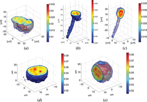
For the measurements we used three test objects. The functionality of the full angular range system has been demonstrated based on the measurements of human malignant lymphoma cells (U937) and human fibrosarcoma cells (HT 1080) specially cultivated and prepared into solution which had been introduced into capillary. In Figure we present the refractive index distribution in a cluster of HT 1080 cells and in U937 cell with extension (highly asymmetrical object).
Figure 6 The examplary results of 3-D refractive index distribution in (a) cluster of HT1080 cells and (b) horizontal and (c) vertical cross-section of HT1080 cell with an extension, (d) horizontal and (e) vertical cross-section of U937 human malignant lymphoma cell.
In a tomography with a limited angular range we analyzed 2 different samples that represent two classes of objects. The first one was human malignant lymphoma cell (U 937). It is a quasi-circular object with smoothly distributed refractive index, thus in the reconstruction process performed, the a priori information consisted of roundness of the outer edge, nonnegative values in the reconstruction domain and smoothness of the inner structure. The angular range of projections was limited to 90° with the angular step between adjacent projections of 1°. To reconstruct the object from limited input data we used the Data Replenishment algorithm. Figure presents the reconstruction calculated after 13 iterations of DRA together with the reference image of the same cell reconstructed with Filtered Back Projection from projections captured within 180° angular range of projections and 1° angular step. Figure (d) shows the value of the error during the reconstruction process. The error was defined in the same way as in Equation 1 and compares result after each iteration with the reference image. For a medium class computer calculating 13 iterations of DRA with reconstruction size of 327 × 327 pixels took 1 second.
Figure 7 The reconstruction of a middle layer of U937 cell (a) from the projections captured from a full angular range (reference image), (b) from the projections taken within 90° with Filtered Back Projection algorithm (c) from the projections taken within 90° with DRA with additional geometry mask (after 13 iterations) and (d) the error calculated after each iteration between the reconstruction and reference image for 30 iterations.
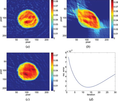
Different colors in Figure represent refractive index differences relative to the background. The error was calculated for 30 iterations to prove that after 13 iterations the quality of the reconstruction decreases. For different objects, the point of minimum error might be at different iteration. It should be noted that in the case of more complicated shape of an object it is no longer possible to create the mask with the approximated geometry of the sample, thus the proposed algorithm cannot be applied.
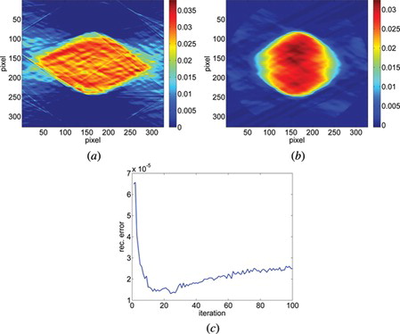
The second object analyzed with our measurement setup was a polymer (PMMA) microsphere. It has a uniform refractive index distribution nD = 1.48. The diameter of the microsphere is 23.5 µm. During measurements the microsphere was mixed with the immersive oil nD = 1.5100 ± 0.0002 (Cargille Labs, NJ, USA) nHe-Ne = 1.5075 (at λ = 632.8 nm). Here we assumed that, in contrast to the U937 cell, the geometry of the object was unknown to us prior to the measurement. The mask with the geometry of the sample was replaced with the a priori knowledge of the sample's piecewise constancy. The measurement setup provided projections captured within 80° angular range with an angular step of 0.38°. Unlike before, we had no access to the rest of the projections, so it was impossible to calculate a real reference image. That is why we calculated a phantom reference image based on the specification of the microsphere. Figures (b) and (c) present the reconstruction of the microsphere after 22 iterations together with the error analysis after each iteration. Figure (a) shows the reconstruction with the same initial data but calculated with the Filtered Back Projection algorithm.
Figure 8 The reconstruction of a middle layer of polymer microsphere (a) from the projections taken within 80° with Filtered Back Projection algorithm (b) from the projections taken within 80° with SART + TVM (after 22 iterations) and (c) the error calculated after each iteration between the reconstruction and reference image for 100 iterations.
8. CONCLUSIONS
We have presented a successful developments and applications of the self-interference Digital Holographic Microscopy in combination with both sample-rotation and illumination-variation tomography modules for 3-D label-free quantitative live cell imaging with sub-cellular resolution. The concept of rotating the specimen is especially convenient when long working distance of a condenser and objective lens is taken into account. It allows for capturing the projections in full angle. On the other hand, the illumination-variation version of the system allows for a fast measurement without moving a sample, but projections can be captured in a limited angle only. The obtained results prove the suitability of the methods to study both quasi symmetrical and highly non-symmetrical objects. We have described the efficient method for a compensation of aberrations due to fiber rotary holder in full-angle tomography as well as we have presented algorithms for compensation for lack of initial data in limited-angle tomography. These approaches have proved to improve the quality of the final reconstruction.
Notes
Color versions of one or more of the figures in the article can be found online at www.tandfonline.com/uopt.
REFERENCES
- Cuche , E. ; Bevilacqua , F. ; Depeursinge , C. Digital holography for quantitative phase-contrast imaging . Opt. Lett. 1999 , 24 , 291 – 293 .
- Lue , N. ; Choi, W.; Popescu, G.; Ikeda, T.; Dasari, R.; Badizadegan, K.; Feld, M. Quantitative phase imaging of live cells using fast Fourier phase microscopy . Appl. Opt. 2007 , 46 , 1836 – 1842 .
- Dubois , F. ; Yourassowsky, C.; Monnom, O.; Legros, J.C.; Debeir, O.; Van Ham, P.; Kiss, R.; Decaestecker, C. Digital holographic microscopy for the three-dimensional dynamic analysis of in vitro cancer cell migration . J. Biomed. Opt. 2006 , 11 , 054032 .
- Kemper , B. ; Carl, D.; Schnekenburger, J.; Bredebusch, I.; Schäfer, M.; Domschke, W.; von Bally, G. Investigation of living pancreas tumor cells by digital holographic microscopy . J. Biomed. Opt. 2006 , 11 , 034005 .
- Marquet , P. ; Rappaz, B.; Magistretti, P.J.; Cuche, E.; Emery, Y.; Colomb, T.; Depeursinge, C. Digital holographic microscopy: A noninvasive contrast imaging technique allowing quantitative visualization of living cells with subwavelength axial accuracy . Opt. Lett. 2005 , 30 , 468 – 470 .
- Charrière , F. ; Marian, A.; Montfort, F.; Kuehn, J.; Colomb, T.; Cuche, E.; Marquet, P.; Depeursinge, C . Cell refractive index tomography by digital holographic microscopy . Opt. Lett. 2006 , 31 , 178 – 180 .
- Debailleul , M. ; Georges, V.; Simon, B.; Morin, R.; Haeberlé, O. High-resolution three-dimensional tomographic diffractive microscopy of transparent inorganic and biological samples . Opt. Lett. 2009 , 34 , 79 – 81 .
- Sung , Y. ; Choi, W.; Fang-Yen, C.; Badizadegan, K.; Dasari, R.R.; Feld, M.S. Optical diffraction tomography for high resolution live cell imaging . Opt. Express 2009 , 17 , 266 – 277 .
- Kozacki , T. ; Kujawińska , M. ; Kniażewski , P. Investigation of limitations of optical diffraction tomography . Opto-Electron. Rev. 2007 , 15 , 102 – 109 .
- Kak , A.C. ; Slaney , M. Principles of Computerized Tomographic Imaging . Society for Industrial and Applied Mathematics , Philadelphia , 2001 .
- Devaney , A.J. A filtered backpropagation algorithm for diffraction tomography. Ultrasonic Imaging 1982 , 4 , 336 – 350 .
- Charrière , F. ; Pavillon, N.; Colomb, T.; Depeursinge, C.; Heger, T.J.; Mitchell, E.A.; Marquet, P.; Rappaz, B. Living specimen tomography by digital holographic microscopy: morphometry of testate amoeba . Opt. Express 2006 , 14 , 7005 – 13 .
- Fauver , M. ; Seibel, E.; Rahn, J.R.; Meyer, M.; Patten, F.; Neumann, T.; Nelson, A. Three-dimensional imaging of single isolated cell nuclei using optical projection tomography. Opt. Express 2005, 13, 4210–23.
- Kus , A. ; Dudek, M.; Kemper, B.; Kujawińska, M.; Vollmer, A. Tomographic phase microscopy of living 3D cell cultures . J. Biomed. Opt. 2014 , 19 , 46009 .
- La Porta , A. ; Wang , M. Optical torque wrench: Angular trapping, rotation, and torque detection of quartz microparticles . Phys. Rev. Lett. 2004 , 92 , 9 – 12 .
- Kreysing , M.K. ; Kiessling, T.; Fritsch, A.; Dietrich, C.; Guck, J.R.; Käs, J.A. The optical cell rotator . Opt. Express 2008 , 16 , 912 – 914 .
- Carmon , G. ; Feingold , M. Controlled alignment of bacterial cells with oscillating optical tweezers . J. Nanophotonics 2011 , 5 , 051803 .
- Bingelyte , V. ; Leach , J. ; Courtial , J. ; Padgett , M.J. Optically controlled three-dimensional rotation of microscopic objects . Appl. Phys. Lett. 2003 , 82 , 829 .
- Hörner , F. ; Woerdemann, M.; Müller, S.; Maier, B.; Denz, C. Full 3D translational and rotational optical control of multiple rod-shaped bacteria . J. Biophotonics 2010 , 3 , 468 – 475 .
- Kus , A. ; Krauze , W. ; Kujawińska , M. Limited-angle hybrid diffraction tomography for biological samples . Proc. SPIE 2014 , 9132 , 9132 – 24 .
- Kim , K. ; Yoon, H.; Diez-Silva, M.; Dao, M.; Dasari, R.R.; Park, Y. High-resolution three-dimensional imaging of red blood cells parasitized by Plasmodium falciparum and in situ hemozoin crystals using optical diffraction tomography . J. Biomed. Opt. 2014 , 19 , 011005 .
- Lauer , V. New approach to optical diffraction tomography yielding a vector equation of diffraction tomography and a novel tomographic microscope . J. Microsc. 2002 , 205 , 165 – 176 .
- Debailleul , M. ; Simon, B.; Georges, V.; Haeberlé, O.; Lauer, V. Holographic microscopy and diffractive microtomography of transparent samples . Meas. Sci. Technol. 2008 , 19 , 074009 .
- Fang-Yen , C. ; Choi, W.; Sung, Y.; Holbrow, C.J.; Dasari, R.R.; Feld, MS. Video-rate tomographic phase microscopy . J. Biomed. Opt. 2011 , 16 , 011005 .
- Cotte , Y. ; Toy, F.; Jourdain, P.; Pavillon, N.; Boss, D.; Magistretti, P.; Marquet, P.; Depeursinge, C. Marker-free phase nanoscopy . Nat. Photonics 2013 , 7 , 113 – 117 .
- Su , T.-W. ; Isikman, S.O.; Bishara, W.; Tseng, D.; Erlinger, A.; Ozcan, A. Multi-angle lensless digital holography for depth resolved imaging on a chip . Opt. Express 2010 , 18 , 9690 – 711 .
- Isikman , S.O. ; Bishara, W.; Mavandadi, S.; Yu, F.W.; Feng, S.; Lau, R.; Ozcan, A. Lens-free optical tomographic microscope with a large imaging volume on a chip . Proc. Natl. Acad. Sci. U. S. A. 2011 , 108 , 7296 – 7301 .
- Wedberg , T.C. ; Stamnes , J.J. ; Singer , W. Comparison of the filtered backpropagation and the filtered backprojection algorithms for quantitative tomography . Appl. Opt. 1995 , 34 , 6575 – 6581 .
- Kostencka , J. ; Kozacki , T. Optical diffraction tomography: accuracy of an off-axis reconstruction . Proc. SPIE 2014 , 9132 , 9132 – 22 .
- Brenner , K.-H. ; Singer , W. Light propagation through microlenses: A new simulation method . Appl. Opt. 1993 , 32 , 4984 – 4988 .
- Taflove , A. ; Hagness , S. Computational Electrodynamics . Artech House : Norwood , 2000 .
- Kozacki , T. ; Falaggis , K. ; Kujawińska , M. Computation of diffracted fields for the case of high numerical aperture using the angular spectrum method . Appl. Opt. 2012 , 51 , 7080 – 8 .
- Fang-Yen , C. ; Choi, W.; Sung, Y.; Holbrow, C.J.; Dasari, R.R.; Feld, MS. Video-rate tomographic phase microscopy . J. Biomed. Opt. 2011 , 16 , 011005
- Natterer , F. The Mathematics of Computerized Tomography . Wiley : New York , 1986 .
- Vertu , S. ; Yamada, I.; Delaunay, J-J.; Haeberlé, O.; Flüge, J. Diffraction microtomography with sample rotation: primary result on the influence of a missing apple core in the recorded frequency space. Proc. SPIE 2009, 7390, 7390-1D.
- Likhachov , A. Projection data replenishment algorithm for limited angle tomography . Optoelec. Instr. Data Proc. 2009 , 45 , 55 – 61 .
- Andersen , A. Simultaneous algebraic reconstruction technique (SART): A superior implementation of the ART algorithm . Ultrasonic Imaging 1984 , 6 , 81 – 94 .
- Verhoeven , D. Limited-data computed tomography algorithms for the physical sciences . Appl. Opt. 1993 , 32 , 3736 – 3754 .
- Krauze , W. ; Kujawińska , M. Limited-angle tomography applied to biological objects . Phot. Lett. Poland 2013 , 5 , 149 – 151 .
- Sidky , E. ; Kao , C. ; Pan , X. Accurate image reconstruction from few-views and limited-angle data in divergent-beam CT . J. X-Ray Sci. Technol. 2006 , 14 , 119 – 139 .
- Takeda , M. ; Ina , H. ; Kobayashi , S. Fourier-transform method of fringe-pattern analysis for computer-based topography; and interferometry . J. Opt. Soc. Am. 1982 . 72 , 156 .
- Kemper , B. ; Vollmer, A.; Rommel, C.E.; Schnekenburger, J.; von Bally, G. Simplified approach for quantitative digital holographic phase contrast imaging of living cells . J. Biomed. Opt. 2011 , 16 , 026014 .
- Ziółkowska , K. ; Stelmachowska, A.; Kwapiszewski, R.; Chudy, M.; Dybko, A.; Brzózka, Z. Long-term three-dimensional cell culture and anticancer drug activity evaluation in a microfluidic chip . Biosens. Bioelectron. 2013 , 40 , 68 – 74 .
- Kostencka , J. ; Kozacki, T.; Kuś, A.; Dudek, M.; Kujawińska, M.; Kemper, B. Holographic method for capillary induced aberration compensation for 3D tomographic measurements of living cells . Proc. SPIE 2013 , 8792 , 8792-04 .
- Garcia , D. Robust smoothing of gridded data in one and higher dimensions with missing values . Comput. Statist. Data Anal. 2010 , 54 , 1167 – 1178 .
- Wang , G. ; Garcia, D.; Liu, Y.; de Jeu, R.; Dolman, J. A three- dimensional gap filling method for large geophysical datasets: Application to global satellite soil moisture observations . Environ. Modell. Softw. 2012 , 30 , 139 – 142 .
- Color versions of one or more of the figures in the article can be found online at www.tandfonline.com/uopt.