
ABSTRACT
This article describes the 3D handheld profiling system composed of a stereo camera and an illumination projector to collect high-resolution data for close range of applications. Visual navigation approach is either based on feature matching or on accurate target, and the target-based approach was found to be more accurate if the 3D object has less texture on its surface. Block matching algorithm was used to render the single-view 3D reconstruction. For multiview 3D modeling, coarse registration and final refinement of the point clouds using iterative closest point algorithm were utilized. The proposed approach yields good accuracy for multiview registration as demonstrated in the results of this research.
Nomenclature
| ANSI | = | American National Standards Institute |
| EKF | = | extended kalman filter |
| HDR | = | high dynamic range |
| ICP | = | iterative closest point |
| IMU | = | inertial measurement unit |
| INS | = | inertial navigation system |
| RANSAC | = | random sample consensus |
| SAD | = | sum of the absolute difference |
| SLAM | = | simultaneous localization and mapping |
| SURF | = | speeded up robust features |
| SVD | = | singular value decomposition |
| λ | = | scaling factor |
| cm | = | centimeter |
| min | = | minute |
| mm | = | millimeter |
| fps | = | frame per second |
| k | = | kilo (1000) |
| s | = | second |
| lumens | = | SI derived unit of Luminous flux |
| µm | = | micrometer |
| m | = | meter |
1. Introduction
Three-dimensional measurements are a fundamental problem in computer vision and some of its interesting applications are virtual reality, medical and scientific imaging, reverse engineering, security, cultural heritage, and industrial inspection. The general classification of the 3D sensing systems includes contact- and noncontact-based techniques. Contact-based techniques have certain disadvantages, i.e., property of touching object, slow performance, and high cost of mechanically calibrated passive arms; and noncontact-based techniques were widely studied to resolve these problems[Citation1,Citation2]. The noncontact-based techniques were further categorized into active and passive techniques, and active techniques solved the correspondence problem associated with the passive stereo vision[Citation3,Citation4]. Active stereo vision-based systems consist of two categories, stereo camera with noncalibrated projector and camera projector system[Citation1]. The 3D sensing systems, i.e., passive stereo, camera projector system, and stereo camera with noncalibrated projector, were comparatively analyzed in our previous research[Citation5]. For the categories of the structured light techniques, single and multiple shots were used for the moving and static 3D objects, respectively, with the strict constraint on acquisition time for the moving object scenario[Citation6]. The problems of self-occlusion, object size, and limited field of view restrict the 3D modeling system to render the 3D model in single measurement and thus multiview integration approach is required[Citation7]. The usage of robotic manipulators, turntables, electromagnetic devices, and passive arms limits user’s mobility and requires high accuracy in external hand-eye calibration and also constitutes the largest and most expensive part of the 3D handheld scanner[Citation7Citation8Citation9]. It is hard to get the real-time pose and position solely from image data as the geometric information from camera is entangled in the radiometric and perspective geometry issues[Citation7]. Inertial measurement unit (IMU) solves this problem through estimating the relative orientation and translation between different views and registering the different view point clouds[Citation9,Citation10].
With the invention of low-cost Microsoft Kinect Sensor[Citation11], high-resolution depth and visual sensing have become available for widespread use. Low-cost 3D handheld scanner based on Kinect fusion was presented in researches[Citation12,Citation13] to create geometrically accurate 3D model in real time using parallel processing. However, the Kinect fusion-based system confronts the problem of reconstructing the highly concave scenes or sharp depth edges[Citation14].
The proposed handheld profiling system consists of a stereo camera and a noncalibrated illumination projector used for the 3D modeling, which is different from the camera-projector-based systems[Citation1]. The 3D sensing systems[Citation3,Citation5,Citation15Citation16Citation17Citation18] are related to the proposed 3D handheld scanning system and are used for the single-view 3D reconstruction. We have previously reported a procedure for the 3D reconstruction for variable zoom using stereo vision and structured light[Citation5], but it was based only on the single-view 3D reconstruction; the hardware was optimized for zoom lens calibration, and the zoom lens control system was designed based on digital image processing and microcontroller. The hardware of the proposed system comprises of a stereo camera and a noncalibrated projector without zoom lenses, and the multiview 3D registration is proposed in this paper.
A mobile 3D scanning system based on a stereo camera and IMU[Citation10] was presented to model the outdoor 3D objects using three-stage heuristic algorithm for multiview registration based on texture similarities and obtained good results as that of Microsoft Kinect. IMU was used to facilitate the registration of the different view point clouds by estimating the orientation and translation of the stereo camera pair. The approaches[Citation19,Citation20] presented a self-referenced, handheld cross-hair laser strip profiling system which consists of a stereo camera and performs its continuous localization using stereo triangulation of the fixed points actively projected on the scene. Active illumination is a cumbersome process as it limits the flexibility of the 3D handheld scanner and affects the laser strip profiling and texturing operations. Another research[Citation7] presents the 3D handheld modeling device for close range applications. This device is characterized by feature-based image processing, 2D monocular image tracking, nonstochastic robust pose estimation, and IMU-supported optical flow prediction. This multisensory 3D modeling device consisting of a stereo camera, laser strip profiler, IMU, and laser range scanner contributed to increase the system’s flexibility and did not use any external positioning systems that restrict the system in size, mobility, and cost. This research mentioned two approaches for visual inertial navigation; fusion of visual and inertial poses either stochastically (or in time) or one sensor supports the pose estimation within the other sensor’s pose estimation process. This research utilized the second approach for the 3D modeling device. The literature also reported the visual inertial navigation approaches[Citation8,Citation9,Citation21Citation22Citation23] based on the fusion of visual and inertial poses. The research[Citation21] reported the fusion of visual and inertial poses based on an extended Kalman filter (EKF) which considered the IMU and camera as “black boxes” to be operated independently. This approach can be used with any pose estimation algorithm, i.e., visual odometry, visual simultaneous localization and mapping (SLAM), monocular or stereo setups. The approach[Citation22] used a key frame-based visual navigation to estimate car motion and used stereo camera and IMU. This approach estimates the states in single optimization with the simultaneous refinement of visual landmarks, biases, and motion to an optimum. Another approach for visual inertial navigation based on EKF framework was reported in Li and Mourikis[Citation23] to estimate the states in an unknown environment. Although this approach was utilized for monocular camera case, it can also be used for stereo camera setup. The research[Citation8,Citation9] presents the state of the art handheld scanner with additional sensors. This work consists of fusion of inertial and visual pose using GraphSLAM framework and this pose information was fed into ICP-based automatic multiview registration approach. The handheld scanner consisted of stereo camera, fringe projection unit, IMU, and high-dynamic range (HDR) camera. The Strobl et al.[Citation24] extended the research[Citation7] avoiding IMU and pointed out that the pose estimation solely from image data not only eliminates the calibration and synchronization problems associated with IMU but also reduces the hardware requirements for the handheld scanning system. 3D handheld scanner in Strobl[Citation7] and Strobl et al.[Citation24] used multiple sensors combined in a compact way while our proposed hardware comprises of a stereo camera and a projector only. The approach[Citation9] used a HDR camera besides stereo camera for visual navigation while we did not use any extra camera for parameter estimation in our research.
This article is an extended version of the handheld 3D scanning research[Citation25]. The remainder of this paper is organized as follows. Section 2 presents the handheld 3D scanning approach and the 3D handheld scanning system. Section 3 describes the visual navigation approach based on accurate target and feature matching. Sections 4 and 5 account for the single-view 3D reconstruction and the multiview registration of the point clouds, respectively. The experiment and measurement results are discussed in Section 6 while Section 7 concludes the handheld scanning approach and also suggests the future work.
2. 3D Handheld scanning approach
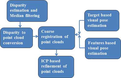
The proposed handheld scanning approach is based on visual navigation, and block matching algorithm was used with structured light technique to render 3D point clouds. The different view point clouds were then aligned with respect to the reference view using coarse and fine registration stages. The proposed approach is depicted in term of a block diagram shown in .
Figure 1. Block diagram of the proposed approach showing different algorithms.
The proposed hardware consists of stereo camera with wide baseline and projector. Several communication interfaces connect the handheld scanner with PC. The proposed system is an extension of the system[Citation5] described for multiview stereo-based 3D handheld scanner in this research. The previous version of this paper[Citation25] reported the system composed of stereo camera and projector connected to the inertial navigation system (INS). The previous version used the handheld scanning approach based on visual inertial navigation, in which the pose of one sensor may support the pose estimation in other sensor. This paper reported the system composed of only the stereo camera and projector without any INS, and pose estimation is based only on visual navigation. The approaches[Citation7,Citation24] for the 3D handheld scanner utilized multiple sensors combined in a compact way while our proposed hardware comprises of a stereo camera and a projector only. The research[Citation9] used a HDR camera besides stereo camera for visual navigation while we do not use any extra camera for parameter estimation in our research.
The stereo camera constitutes a pair of Basler Ace2500 14/gm monochrome cameras connected with A100P Zeus pocket projector. The proposed hardware and specifications of the camera and projector are shown in and , respectively.
Figure 2. Hardware of the proposed 3D handheld scanning system.
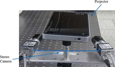
Table 1. Specifications of the camera and the projector.
3. Visual pose estimation
Our approach is based on visual navigation to estimate the orientation and position of the 3D scanning system with certain accuracy. The parameters estimated from visual navigation are utilized to align the different view point clouds in coarse registration.
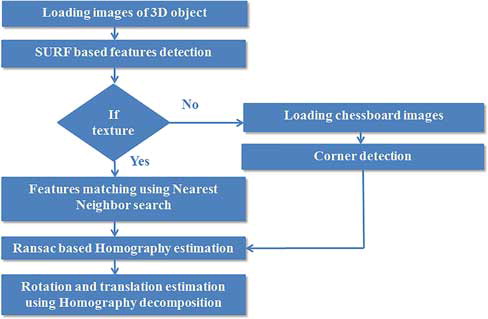
Two approaches for visual pose estimation based on features matching using speeded up robust features (SURF)[Citation26] and the chessboard target were applied in this research. In case of sufficient 2D features or texture on the surface of 3D object, feature-based approach was applied. When texture or enough features are not available, the chessboard target was used for accurate pose estimation. Both the approaches are based on random sample consensus (RANSAC)-based homography estimation[Citation27,Citation28] between images of different viewpoints and homography decomposition yields the relative pose and position provided that the intrinsic parameters of single camera are known by precalibration. The precalibration stage was performed using Zhang’s method[Citation29] and the chessboard target. The block diagram of visual navigation is shown in .
Figure 3. Visual pose estimation for the 3D handheld scanning system.
The equations for the homography estimation are as follows:
After estimating the homography between the two views with or without the chessboard target, the relative rotation and translation parameters may be determined through homography decomposition if the intrinsic camera matrix is known. The equations governing the homography decomposition are as follows:
ri = ith column of 3 × 3 rotation matrix; hi = 3-by-1 vector, i = 1 to 3; λ = scaling factor; M = intrinsic matrix of camera (known by precalibration).
4. Single-view 3D reconstruction
The single-view 3D reconstruction includes the projection of the single shot structured light pattern on the static 3D object, and the block matching algorithm was used for stereo matching. M-array-based single-shot pattern was used in this research due to the stringent constraint on acquisition time[Citation6].
4.1. Structured light technique
M-array or perfect map is a random array of dimensions a × b in which p × q subarray is unique. We can reconstruct the perfect map theoretically using equation ab = 2pq, but practically the zero submatrix is not considered and the number of unique subarrays of p × q size is ab = 2pq −1[Citation1]. Since M-array was used previously for the camera projector systems in the literature, we made a contribution using binary-coded M-array pattern[Citation30] for our proposed scanning system. This pattern has the following constraints:
The pattern has only one symbol of white square.
There is no connectivity constraint between the white squares.
There is no repeated code word within the pattern.
The binary-coded pattern has certain benefits, i.e., the correspondence problem was simplified using unique window property while less number of symbols and the connectivity constraint led to simplify the pattern segmentation in decoding process[Citation30].
We have further used the pixel replication to increase the resolution of the pattern. The pixel replication replaces the zeros or ones with m × m grid of the same symbol. shows the 200 × 200 pattern having 9 × 9 unique window property using m = 2 for the pixel replication process.
Figure 4. (200 × 200) pattern generated with (9 × 9) unique window and m = 2.

4.2. Stereo matching and the point cloud acquisition
M-array-based structured light patterns were previously used for the camera projector systems, and conventional decoding methods were used on the ideal pattern image and the captured image[Citation1,Citation30]. For our proposed system, based on stereo camera and noncalibrated projector, we do not need the conventional decoding methods, and stereo matching was performed on the stereo images captured with the projected pattern.
Fast and effective block matching algorithm similar to that in research[Citation31] was applied on the stereo images to accomplish the single-view 3D reconstruction. This algorithm is based on sum of the absolute difference (SAD) for matching the stereo pair and calculates the depth for every pixel on the 3D objects or scenes with strong texture. This algorithm is based on three steps[Citation27]:
Prefiltering the images to enhance brightness and texture.
Finding correspondence along the horizontal epipolar lines using SAD window.
Postfiltering to remove bad correspondence matches.
After finding the correspondences in the stereo pair, the relationship between the 2D points in homogenous coordinate and the 3D coordinate is given by Equation (7). Median filtering[Citation32] using large-sized window was applied on the disparity images, and the acquisition of the point cloud data was accomplished as follows:
5. Multiview 3D registration
Three-dimensional registration is performed in two steps, namely, coarse and fine registration[Citation33]. Our approach is based on the two stages of registration, such as coarse registration and final refinement using ICP algorithm. Coarse registration uses the relative orientation and translation parameters estimated in Section 3 and transforms the different view point clouds with respect to the reference view. The roughly registered point clouds were then refined using ICP.
The transformation of the different view point clouds into the reference view using the parameters estimated through visual navigation is the coarse registration stage. The coarse registration is mathematically defined as follows:
The refinement of the coarsely registered point clouds was performed using ICP algorithm[Citation33]. This algorithm automatically finds correspondences between the different view point clouds without following the particular order of the acquisition of the point clouds and without any knowledge about the overlap between them. We applied this algorithm to refine the point clouds, which are in approximate registration with the reference view. The main steps of ICP algorithm are as follows:
Delaunay triangulation and convex hull estimation-based nearest-neighbor search was used to establish correspondences between ith view and the reference view point clouds.
The translation and rotation parameters between the matched point clouds were estimated using the singular value decomposition (SVD).
The ith view point cloud was transformed into the coordinate of the reference view point cloud using the rotation and translation parameters.
The above steps are repeated till ICP converges to the desired solution.
Let ‘A’ and ‘B’ be the two point clouds as inputs to the ICP algorithm. A1 to An and B1 to Bn are the point clouds matched using nearest-neighbor search while the centroids of the point clouds are indicated as Ca and Cb, respectively. The 3 × 3 covariance matrix ‘M’ was calculated as follows:
To estimate the rotation “R” and the translation “T” between the two point clouds, covariance matrix ‘M’ was decomposed into ‘U’ and ‘V’ matrices using SVD and the equations are as follows:
The accuracy for the ICP algorithm is the mean error distance between the reference view and other view point cloud normalized by resolution or tolerance distance to establish closest point correspondences. The formula for error measurement is given below:
6. Measurement results
We used an artificial skull object to demonstrate the proposed handheld scanning system for biomedical applications. We placed the object at 30 cm from the scanner with the projection of the M-array pattern on it. shows the stereo camera images with the projection of M-array pattern on an artificial skull. Since we used the block matching algorithm for the single-view 3D reconstruction and applied median filtering on the disparity images of different views as mentioned in Section 4. So, the disparity image for one view before and after the median filtering is depicted in , which shows the smoothing of the disparity image. The number of 3D points in four view point clouds and the percentage decrease in the number of the 3D points in the point clouds before and after applying the median filtering is shown in .
Figure 5. The stereo images with the projection of the M-Array pattern on the skull phantom, (a) the left camera image and (b) the right camera image.
Figure 6. The disparity image for one view, (a) before median filtering and (b) after median filtering.
Table 2. Number of the 3D points in different view point clouds and the percentage decrease in the 3D points before and after applying the median filtering.
We also performed two experiments with the skull object and the chessboard target to evaluate our visual navigation algorithm. We fixed the hardware of the 3D scanning system on a rotational stage, the system was rotated to 10° for six times along y-axis and the results of this experiment are shown in for both the feature-based and target-based visual navigation. In second experiment, the system was fixed on a translational stage and the system was translated along the z-axis for 25 mm six times. The procedure for the experiment and the results are reported in for both the feature-based and the target-based visual navigation. Since the skull object has less texture on its surface, the target-based visual navigation has better accuracy as compared to the feature-based algorithm as shown in and .
Table 3. Visual navigation result to estimate the rotation along y-axis for the feature-based and target-based approaches.
Table 4. Visual navigation result to estimate the translation along z-axis for the feature-based and target-based approaches.
Single-view 3D reconstruction renders the point clouds of different views, and shows the visualization of the reference view and the three different view point clouds at the same time in Geomagic Verify Viewer software before ICP-based refinement. The reference view and the three different view point clouds after ICP-based refinement are visualized in , which shows that the shape of skull is more visible as compared to the visualization in . This result indicates the good alignment of three-point clouds with reference view and the shape of skull was also improved. The results of the point clouds after applying the median filtering and the multiview 3D registration are depicted in and , which shows the enhancement of the point clouds after removing noise. The accuracy of the ICP algorithm is shown in and the normalized mean error for the pair of point clouds (after median filtering) is reported for the resolution of 0.05 mm.
Figure 7. The multiview registration of the point clouds without median filtering, (a) visualization of reference view and the three different view point clouds before ICP and (b) visualization of the same point clouds after ICP.
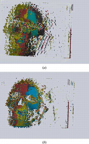
Figure 8. The multiview registration of the point clouds with median filtering, (a) visualization of reference view and the three different view point clouds before ICP and (b) visualization of the same point clouds after ICP.
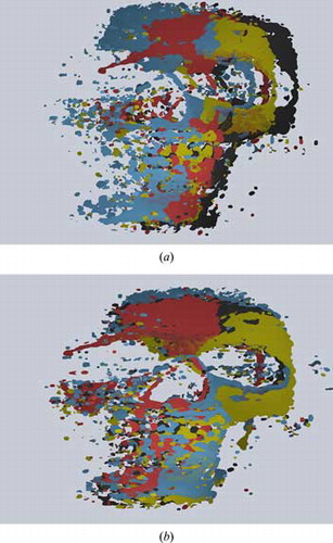
Table 5. Accuracy of the ICP algorithm in term of normalized mean error for the registration of the reference view point cloud and ith point cloud.
To provide a surface divergence between the 3D model of the skull phantom and the single scan, we used the single 3D scan produced by the proposed system and the 3D model generated from a multiple-shot-based structured light scanner[Citation5]. This 3D model was generated using multiple-shot structured light technique and multiple views were registered using rough registration and ICP algorithm[Citation34,Citation35]. shows the visualization of the 3D model in MeshLab software while depicts the surface divergence result between the single 3D scan and the 3D model using CloudCompare[Citation36] software. The mean error of the signed distances between the 3D model and the single scan was 0.01 mm and the standard deviation was found to be 2.15 mm.
Figure 9. The comparison of the 3D model (generated by approach[Citation5,Citation34,Citation35]) with the single scan, (a) visualization of the 3D model of skull phantom generated by multiple-shot-based structured light scanner (b) surface divergence of the single-scan and 3D model.
![Figure 9. The comparison of the 3D model (generated by approach[Citation5,Citation34,Citation35]) with the single scan, (a) visualization of the 3D model of skull phantom generated by multiple-shot-based structured light scanner (b) surface divergence of the single-scan and 3D model.](/cms/asset/f2111c7b-f63f-4428-9482-698a374c547e/uopt_a_1300968_f0009_oc.jpg)
For the 3D handheld scanning, the important consideration is the acquisition time. The processing time for the different algorithms is recorded in . The overall time without using parallel processing was found to be less than 1 min. In case of strong texture, the target-based visual estimation is skipped. If there is no sufficient texture, all steps are included for overall processing time ().
Table 6. Processing time for the different algorithms.
7. Conclusion
This paper discusses the implementation of a handheld scanning system using visual navigation and the structured light. The system is composed of a stereo camera and a projector and utilized the features and the target-based approach for visual navigation. M-array-based structured light and the block matching algorithm performed single-view 3D reconstruction. Multiview 3D registration based on coarse and final refinement stages further improves the accuracy of the 3D scanning. The scanning system is potentially beneficial for the applications in biomedical imaging.
The handheld scanning system is capable of yielding 700–900 k data points per scan. The visual navigation resulted in the mean error of 0.85 mm and 0.29° in the translation and rotation, respectively. The comparison of our system and the 3D modeler[Citation7] shows that our system has higher accuracy in estimating the orientation and position while the 3D modeler has a longer working range of 30 cm to 2 m and has less scanning time.
The scanning time can be further reduced using feature-based stereo vision without processing the whole images. One of the possible choices to reduce scanning time is to use parallel processing and assigning separate threads to different algorithms to match the application need of scanning time. The feature matching-based visual navigation can be further improved to avoid the chessboard target for the handheld scanning research.
References
- Salvi, J. A state of the art in structured light patterns for surface profilometry. Pattern Recognit. 2010, 43, 2666–2680.
- Li, Y.; Gu, P. Free-form surface inspection techniques state of the art review. Comput. Aided Des. 2004, 36, 1395–1417.
- Bruno, F. Experimentation of structured light and stereo vision for underwater 3-D reconstruction. ISPRS J. Photogram. Remote Sens. 2011, 66, 508–518.
- Shi, C.-Q.; Zhang, L.-Y. A 3-D shape measurement system based on random pattern projection. In 2010 Fifth International Conference on Frontier of Computer Science and Technology (FCST), Changchun, Jilin Province, China, August 18–22, 2010, IEEE Computer Society, Los Alamitos, CA, 2010.
- Kim, M.Y.; Ayaz, S.M.; Park, J.; Roh, Y. Adaptive 3-D sensing system based on variable magnification using stereo vision and structured light. Opt. Lasers Eng. 2014, 55, 113–127.
- Geng, J. Structured-light 3-D surface imaging: A tutorial. Adv. Opt. Photon. 2011, 3, 128–160.
- Strobl, K.H. The self-referenced DLR 3-D-modeler. In IEEE/RSJ International Conference on Intelligent Robots and Systems, 2009 (IROS 2009), Hyatt Regency St. Louis Riverfront, St. Louis, MO, USA, October 10–15, 2009; IEEE: Washington, DC, USA, 2009.
- Munkelt, C. Hand-held 3-D scanning with automatic multi-view registration based on optical and inertial pose estimation. In Wolfgang Osten, Fringe 2013; Springer: Berlin, Heidelberg, 2014; pp. 809–814.
- Kleiner, B. Hand-held 3-D scanning with automatic multi-view registration based on visual-inertial navigation. Int. J. Optomechatron. 2014, 8, 313–325.
- Byczkowski, T.; Lang, J. A stereo-based system with inertial navigation for outdoor 3-D scanning. In Canadian Conference on Computer and Robot Vision, 2009 (CRV′09), Kelowna, British Columbia, Canada, May 25–27, 2009; IEEE: Washington, DC, USA, 2009.
- Zhang, Z. Microsoft kinect sensor and its effect. IEEE MultiMedia 2012, 19, 4–10.
- Newcombe, R.A. KinectFusion: Real-time dense surface mapping and tracking. In 2011 10th IEEE International Symposium on Mixed and Augmented Reality (ISMAR), Basel, Switzerland, October 26–29, 2011, IEEE: Washington, DC, USA, 2011.
- Izadi, S. KinectFusion: Real-time 3-D reconstruction and interaction using a moving depth camera. In Proceedings of the 24th Annual ACM Symposium on User Interface Software and Technology, Santa Barbara, CA, USA, October 16–19, 2011; ACM: New York, NY, USA, 2011.
- Han, J. Enhanced computer vision with microsoft kinect sensor: A review. IEEE Trans. Cybernet. 2013, 43, 1318–1334.
- Schaffer, M.; Grosse, M.; Kowarschik, R. High-speed pattern projection for three-dimensional shape measurement using laser speckles. Appl. Opt. 2010, 49, 3622–3629.
- An, D.; Woodward, A.; Delmas, P.; Gimel’farb, G.; Morris, J.; Marquez, J. Comparison of active structure lighting mono and stereo camera systems: Application to 3-D face acquisition. In Seventh Mexican International Conference on Computer Science 2006 (ENC′06), San Luis Potosi, Mexico, September 18–22, 2006; IEEE Computer Society: Washington, DC, USA, 2006.
- Hu, E.; He, Y. Surface profile measurement of moving objects by using an improved π phase-shifting Fourier transform profilometry. Opt. Lasers Eng. 2009, 47, 57–61.
- Chen, C.-S.; Hung, Y.-P.; Chiang, C.-C.; Wu, J.-L. Range data acquisition using color structured lighting, & stereo vision. Image Vis. Comput. 1997, 15, 445–456.
- Hébert, P. A self-referenced hand-held range sensor. In Proceedings of Third International Conference on 3-D Digital Imaging and Modeling, Quebec City, Canada, 28 May–1 June, 2001; IEEE Computer Society: Los Alamitos, CA, 2001.
- Khoury, R. An enhanced positioning algorithm for a self-referencing hand-held 3-D sensor. In The 3rd Canadian Conference on Computer and Robot Vision, Quebec City, Canada, June 7–9, 2006; IEEE Computer Society: Los Alamitos, CA, 2006.
- Weiss, S.; Siegwart, R. Real-time metric state estimation for modular vision-inertial systems. In 2011 IEEE International Conference on Robotics and Automation (ICRA), International Conference Center, Shanghai, China, May 9–13, 2011; IEEE: Washington, DC, 2011, pp. 4531–4537.
- Leutenegger, S.; Furgale, P.; Rabaud, V.; Chli, M.; Konolige, K.; Siegwart, R. Keyframe based visual-inertial SLAM using nonlinear optimization. In Proceedings of Robotics: Science and Systems, Berlin, Germany, June 24–28, RSS Foundation: National University of Singapore, Republic of Singapore, 2013 (online proceedings).
- Li, M.; Mourikis, A.I. High-precision, consistent EKF-based visual–inertial odometry. Int. J. Robot. Res. 2013, 32, 690–711.
- Strobl, K.H.; Mair, E.; Hirzinger, G. Image-based pose estimation for 3-D modeling in rapid, hand-held motion. In 2011 IEEE International Conference on Robotics and Automation (ICRA), International Conference Center, Shanghai, China, May 9–13, 2011; IEEE: Washington, DC, 2011.
- Ayaz, S.M.; Danish, K.; Bang, J.Y.; Park, S.I.; Roh, Y.; Kim, M.Y. A multi-view stereo based 3-D hand-held scanning system using visual-inertial navigation and structured light. In MATEC Web of Conferences, Neuchatel, Switzerland, October 14–16, 2015; EDP Sciences Publisher: France, 2015; 32, pp. 06004.
- Bay, H. Speeded-up robust features (SURF). Comput. Vis. Image Understand. 2008, 110, 346–359.
- Bradski, G.; Kaehler, A. Learning OpenCV: Computer Vision with the OpenCV Library. O’Reilly Media, Inc.: California, USA, 2008.
- Fischler, M.A.; Bolles, R.C. Random sample consensus: A paradigm for model fitting with applications to image analysis and automated cartography. Commun. ACM 1981, 24, 381–395.
- Zhang, Z.A flexible new technique for camera calibration. IEEE Trans. Pattern Anal. Mach. Intelligence 2000, 22, 1330–1334.
- Wijenayake, U.; Park, S.-Y. Dual pseudorandom array technique for error correction and hole filling of color structured-light three-dimensional scanning. Opt. Eng. 2015, 54, 043109–043109.
- Konolige, K. Small vision systems: Hardware and implementation. Robot. Res. 1998, 8 (Robotics Research, The Eighth International Symposium), 203–212 (Springer: London).
- Lim, J.S. Two-dimensional Signal and Image Processing. Prentice Hall: Englewood Cliffs, NJ, 1990, 710 p.
- Mian, A.S.; Bennamoun, M.; Owens, R. Three-dimensional model-based object recognition and segmentation in cluttered scenes. IEEE Trans. Pattern Anal. Mach. Intelligence 2006, 28, 1584–1601.
- Chen, Y.; Medioni, G. Object modelling by registration of multiple range images. Image Vis. Comput. 1992, 10, 145–155 (Butterworth-Heinemann).
- Besl, P.J.; McKay, N.D. A method for registration of 3-D shapes. IEEE Trans. Pattern Anal. Mach. Intelligence 1992, 14, 239–256 (IEEE Computer Society: Los Alamitos, CA).
- Girardeau-Montaut, D. Cloud Compare: 3D point cloud and mesh processing software, open-source project. On-line: http://www.danielgm.net/cc, Accessed 2016, 4 (03).