Abstract
In this work, a series of novel isotropically conductive adhesives (ICAs) based on multiwalled carbon nanotube (MWCNT)-modified liquid crystalline epoxy (LCE) resin was prepared. Different loadings of MWCNTs were used to produce LCE composites. Transmission electron microscope, scanning electron microscope, differential scanning calorimetry, polarized light optical microscopy, X-ray diffraction, electrical conductivity measurement, and tensile and flexural measurements were used to characterize the morphology, thermal, phase change, electrical, and mechanical properties of the prepared composites. The results showed that the added MWCNTs were dispersed well in the LCE matrix. The introducing MWCNTs did not show any major influence on typical curing peaks of LCE. Electrical conductivity at room temperature of the composites was increased significantly compared with neat LCE. The conductivity value of 10−2 S cm−1 was obtained at a weight concentration of only 0.5% MWCNT. In addition, tensile strength, Young’s modulus, flexural strength, and flexural modulus of the composites were increased clearly compared with neat LCE matrix. These produced LCE composites with very low MWCNT loadings showed a great prospect of being used as ICAs.
1. Introduction
In recent years, electronic interconnections have been dominated by electrically conductive adhesives in response to environmental legislations.[Citation1] Among electrically conductive adhesives, isotropically conductive adhesives (ICAs) with metallic fillers have gained a lot of commercial significance. However, due to the presence of metallic fillers, such adhesives show decrease in conductivity after exposure to moisture because of corrosion at the interface of substrate and component. As reported, metallic filler was already replaced with organic conducting polymers such as polyaniline [Citation2] and polypyrrole.[Citation3] Replacing metallic fillers with carbon nanotubes (CNTs) also can help in overcoming these problems. In addition, due to small size and better compatibility of CNTs, maximum mechanical performances of matrix can be retained. Also, loss of conductivity due to corrosion can be prevented.
Carbon nanotubes with excellent thermal, electrical, and magnetic properties have received much interest in fabricating advanced materials. Because of low density, high aspect ratio, extraordinary strength, and flexibility, CNTs seem to become ideal reinforcing fibers to fabricate composites.[Citation4–8] For CNTs to effectively enhance the properties of a composite, the CNTs must be deagglomerated, well dispersed, and have sufficient interfacial interaction with the host matrix.[Citation9–11]
One of the most widely used matrices for ICAs are epoxies. Epoxy resins are widely used in industrial applications, as construction materials; in automobile industry; and in aerospace applications, as adhesives, coatings, electronic circuit board laminates, etc., due to their good stiffness, dimensional stability, good chemical and water resistance, low cost, ease of processing, fine adhesion to many substrates, low specific weight, low shrinkage on cure, and long pot life period.[Citation12–15]
Epoxy/CNT composites have been prepared by a number of groups. Gojny tried to use calendaring for dispersing CNTs in a viscous epoxy matrix [Citation16]. Martin [Citation17] dispersed multiwalled carbon nanotubes (MWCNTs) in an epoxy system based on bisphenol A and studied the influence of AC and DC electric fields on alignment of conductive networks. Li and Lumpp used MWCNT of various aspect ratios to develop conductive adhesives for aerospace applications.[Citation18] Composites with very high conductivity also have been developed through RIM technique recently.[Citation19] Though lots of literatures on epoxy/CNT composites have been studied in recent years, fewer reports are on the liquid crystalline epoxy (LCE) resins, which may exhibit some excellent unique performances.
LCE resins have many outstanding performances in heat resistance, mechanical properties, optical properties, and dielectric properties, which attract more and more attention of researchers.[Citation20,21] Several kinds of LCE resins were reported, such as biphenyl,[Citation22,23] aromatic ester,[Citation24] azomethine,[Citation25] and stilbene.[Citation26] In order to obtain LCE for high-performance applications, great efforts have been made to study the composite based on LCE resin and reinforced materials. In this work, a series of novel ICAs with better stability and electrical properties have been developed and reported based on MWCNT-modified azo-containing LCE. The thermal, phase change, mechanical, electrical, and morphological characteristics of MWCNT/LCE composites were investigated as a function of filler content. Percolation threshold is very low, and conductivity value of 10−2 S cm−1 is obtained at an added MWCNT concentration of only 0.5%.
2. Experimental
2.1. Materials
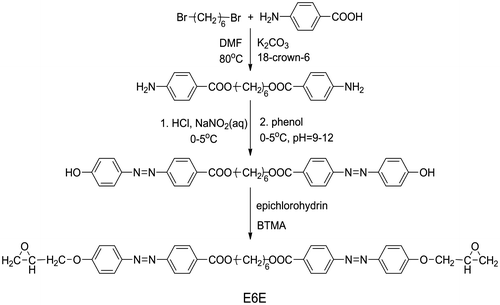
The azo-containing LCE monomer, α,ω-bis[4-(2,3-epoxypropoxy) azobenzene-4′-carbonyloxy]alkane (E6E), was synthesized in our laboratory. The prepared process and chemical structure of E6E was shown in Scheme . The curing agent tetrahydrophthalic anhydride (THPA) was purchased from Alfa Aesar and used as received. The used MWCNT was supplied from Bayer Material Science AG (Leverkusen, Germany) synthesized by catalytic carbon vapor disposition process (purity > 98%, average diameter 5–15 nm, length > 100 mm). Azobenzene (AR) and dichloromethane (AR) were obtained from Sinopharm Chemical Reagent Co., Ltd, Shanghai China.
2.2. Composites preparation
Appropriate amount of MWCNTs was weighted according to the required percentage so that the final concentrations of composite will be 0.3%, 0.5%, and 1.0%. The MWCNTs were dispersed in dichloromethane by mechanical stirring and ultrasonication for 1 h at 45 °C to form a homogeneous suspension. Then, the stoichiometric amount of E6E and THPA were added with mechanical stirring and ultrasonication for next 2 h at 50 °C in dichloromethane, and finally, the solvent was removed and dried in vacuum at room temperature. Each sample was stored in a freezer at −10 °C. If necessary, some testing samples were heated under the curing temperature and left undisturbed for some time to remove air bubbles prior to further use. The compositions and codes of prepared samples were list in Table .
Table 1. Compositions and codes of E6E/THPA and its composites with MWCNTs.
2.3. Characterization
1H NMR spectrum was obtained with a Bruker DRX-400 spectrometer using CDCl3 as the solvent and tetramethylsilane as the internal standard.
Calorimetric measurements were performed using a Perkin-Elmer differential scanning calorimetry (DSC) 7 thermal analyzer under nitrogen atmosphere to measure the heat flow under non-isothermal conditions. The test samples were non-cured. The mass of samples was about 8–10 mg. The dynamic DSC tests were conducted from 50 to 300 °C at a 10 °C min−1 heating rate.
The texture of the liquid crystalline phase was examined by a polarized light optical microscopy (POM) (Caikon Optic Equipment, Shanghai China) equipped with a (CK-300) hot stage. The cure of the mixture was carried on the hot stage between two thin glass slip. The POM was conducted to observe the texture change during curing. X-ray diffraction (XRD) measurement was studied with a Rigaku Diffractometer (D/MAX-1200) to confirm the mesophase.
Conductivity was measured by means of the standard in line four-probe method using semiconductor characterization system of Keithley Instruments, Inc., Cleveland, OH, USA (model 4200). Both surfaces of the films were scratched using flint paper before measurements to ensure proper contact.
Tensile and flexural properties of neat LCE and the composites were measured on a universal testing machine (RGM-3030, Shenzhen Reger Instrument) at room temperature following ASTM-D638 and ASTM-D, respectively. Dimensions of specimens were 120 mm × 10 mm × 3 mm, and crosshead speed was 5 mm min−1. The reported values are averages obtained with five specimens.
Effect of environmental aging on the cured samples was studied by conditioning at 75 °C/~100% RH until 30 days and measuring the weight gain after various time periods. Five samples of each adhesive were laid on a standard square glass coverslip and cured for 1 h at 150 °C in a preheated oven. The cured samples were weighed on a Mettler instruments, Greifensee, Switzerland balance (AE-240) and placed on a plastic mesh above the water level in a temperature controlled water bath. Selected samples were periodically removed and weighed at aging times. The water bath was maintained at 75 °C and tightly closed except when samples were removed for testing so that the relative humidity in the water bath chamber was nearly 100%.
Transmission electron microscope (TEM) observations were carried out using a high-resolution TEM JEM-2100 (JEOL, Japan) with an accelerating voltage of 200 kV to examine the morphology of dispersion of MWCNTs. Samples were cut into 50 nm thick films by ultramicrotome. For the observation of the nanopowders, MWCNTs were dispersed in ethanol under sonication for 10 min. Then, the suspension was dropped on a copper grid and analyzed by TEM.
The morphology of fractured surface of LCE composites was recorded under a PHILIPS XL-30 scanning electron microscope (SEM) operated at 20 kV after samples were sputtered with gold.
3. Results and discussion
3.1. Synthesis and characterization of monomer
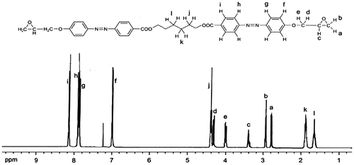
Epoxy monomer was synthesized through the well-known simple reactions given in Scheme . The first and the third synthetic steps were followed reported procedures. The second synthetic step involves the diazotization of amino group and the coupling reaction of the diazonium salt and phenol. The reaction conditions are the same with the common synthesis procedure of the azobenzene. The diazotization of amino group was proceeded under pH 2–5 and T = 0–5 °C. After diazotization, small amount of urea was added to remove the residual nitrous acid. The diazonium salt reacts with phenol under pH 9–11 and T = 0–5 °C. The diphenol containing azobenzene precipitated from the solution was filtrated and washed with water and then with ethanol. The synthesized epoxy monomer was characterized by means of 1H NMR technique (see Figure ). 1H NMR (CDCl3, δ): 8.14(d, 4H), 7.90(d, 4H), 7.88(d, 4H), 7.00(d, 4H), 4.38(t, 4H), 4.30(dd, 2H), 4.00(dd, 2H), 3.39(m, 2H), 2.92(t, 2H), 2.78(dd, 2H), 1.88(t, 4H), 1.65(t, 2H). The spectrum of epoxy monomer (E6E) suggested that the purity is high.
3.2. Curing and phase change behaviors
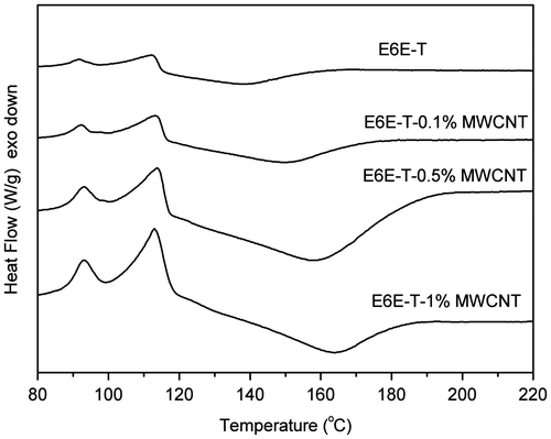
DSC measurement gives information about the curing process. In the work, DSC was used to study the curing behaviors of the prepared composites. The DSC plots of E6E/THPA mixture and its composites with MWCNTs obtained during first heating in modulated DSC scan are shown in Figure . The initial exothermic peak of E6E/THPA sample appears at 118 °C, depicting the crosslinking reaction of the epoxy system. A single curing peak is observed in all the samples, which depicts that the basic curing profile of epoxy remains unaffected by the presence of MWCNTs. With the increase in MWCNT content, the peak slightly shifts toward higher temperature. This is due to an increase in uncured part in the matrix. However, this influence on the E6E/THPA system by addition of different loadings of MWCNT is slight. All the results clearly show that due to smaller size and high aspect ratio of MWCNT, they provide least hindrance to crosslinking network in E6E/THPA system. In addition, anhydrides used as the curing agent of epoxy resins, their activity is lower than the amines. Usually, an accelerator is added to the curing system of epoxy/anhydride. However, what to our surprise is that the curing reaction occurred at a low temperature (118 °C for E6E) without any extra accelerator, which is lower than that in the literature (150 °C).[Citation27] The curing reaction of E6E/THPA may be accelerated by the azo groups in the system.
From a dynamic DSC run, the total area of the exothermal peak (the region between the exotherm and the baseline) is in direct proportion to the molar reaction heat, the ΔH released during the whole cure reaction.[Citation28] The extent of the curing at any temperature can be expressed as(1)
where ΔHs is the heat of reaction of the partially cured samples heated up to the temperature T. The cure rate, dα/dt, is defined by
(2)
where α is the degree of curing, (dΔH/dt)T is the heat absorption rate during the scanning (J s−1 g−1 = W g−1), and ΔH0 is the total amount of heat absorbed (J g−1).
Figure reveals a comparison of the curing kinetics among the E6E/THPA and its nanocomposite modified by MWCNT systems. The value of α is list in Table .
Figure 3. Advancement of the curing for the non-isothermal curing of E6E-T and its composite samples.
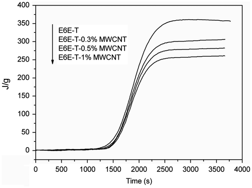
Table 2. Mesophase behavior of E6E and the degree of curing of the composites calculated by DSC.
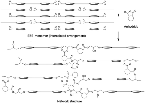
The mesophase behavior of E6E has been shown in Table . The E6E monomer shows smectic A (SA) phase. The mesophase of E6E is affected by the central space. The E6E favors an intercalated arrangement to form smectic phase.[Citation29] Figure depicts the arrangements of mesogens before and after curing of E6E. After the melting of the E6E, the mesogens exhibit an intercalated arrangement, in which many epoxy groups hided. In order to make the epoxy and anhydride groups get enough close to react, a rearrangement of mesogens to expose the epoxy groups is necessary. Much energy was needed for the arrangement change of mesogens from the much higher ordered intercalated structure to a lower ordered one, which leaded to a large value of the curing activation energy (Ea).
In essence, the rearrangement of the mesogens is the diffusion of the epoxy resins. For the high energy needing of the rearrangement during the curing process, the apparent activation energy Ea is the sum of the chemical activation energy and diffusion activation energy. Unlike the two-stage behavior of LCE curing system in the literature,[Citation30] the two mechanisms dominate the curing together in the E6E/THPA system in our work.
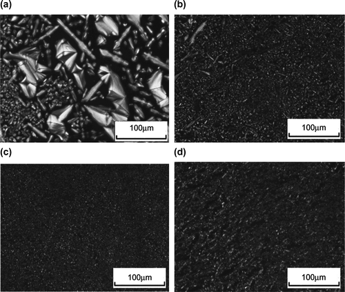
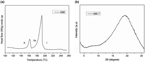
Phase change of E6E during the isothermal curing is shown in Figure . For E6E, only a SA mesophase is observed, suggested by the focal conic fan texture. After the melting of E6E-T sample at 175 °C (0 min), there are many rod-like textures of SA phase (intercalated arrangement) in the POM photograph. After 10 min, the rod-like textures disappeared and the rearrangement of the mesogens lead to a nematic phase finally. There are two endothermic peaks on the DSC plot of E6E corresponding to melting transition, SA, and isotropization (Figure (a)). The nematic phase is further confirmed by XRD result, which shows a broad peak at 2θ = 19.27° (Figure (b)). The LCE from E6E/THPA has the nematic phase because the large amount of anhydride hardener for complete cure brings too many distortions to form a smectic phase.
3.3. Electrical conductivity
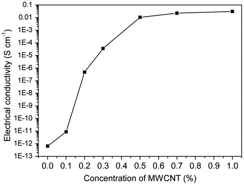
Electrical conductivity of a material corresponds to the ease at which the charge flows in it. For a composite material, it depends on the characteristics of the filler component and its subsequent arrangement inside the matrix. When the conductive MWCNTs are incorporated, the insulating matrix is traversed by the conductive MWCNTs which form clusters. When these clusters align themselves throughout the matrix, they form conductive channels due to contact between adjacent nanostructures. Electrical conductivities at room temperature of neat LCE and its composites with different MWCNT contents are shown in Figure . As can be seen, electrical conductivity for neat LCE is 6.658 × 10⁻¹³ S cm−1. Incorporation of MWCNT increases of the conductivity significantly compared with the neat LCE. The conductivity can reach 1.068 × 10⁻² S cm−1 when concentration of MWCNTs is 0.5%. When the loading is higher than 0.5%, the composites behave slow improvement in conductivity. The smooth propagation of conductivity indicates that the dispersion of MWCNTs inside the matrix is uniform and proper conductive channels have been formed. Composites containing conductive filler in insulating polymers become electrically conductive when the filler content exceeds a critical value, known as a percolation threshold. The percolation threshold is characterized by a sharp jump in the conductivity by many orders of magnitude, which is attributed to the formation of a three-dimensional conductive network of the fillers within the matrix. As shown in Figure , there is a sharp increase in conductivity around 0.1% concentration which is due to high conductivity of MWCNT. The tremendously increasing of electrical conductivity implies that percolation threshold for the composite is above 0.1% of MWCNT nanostructure content. The percolation threshold of these composites taken around 10−6 S cm−1 is at a very low MWCNT concentration of 0.2%. This very low percolation threshold is due to the high aspect ratio and nanodimensions of MWCNTs.
3.4. Mechanical properties
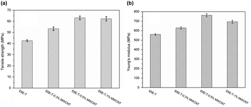
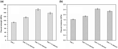
Mechanical properties including tensile strength, Young’s modulus, flexural strength, and flexural modulus of the LCE composites with different MWCNT contents are shown in Figures and . As can be seen, both tensile and flexure properties of the composites improve as MWCNT content increases. In Figure , comparing the mechanical properties of E6E-T with E6E-T-0.5% MWCNT, it has been found that tensile strength is increased by 48% from 42.6 to 63.1 MPa. Young’s modulus is increased by 36% from 560 to 760 MPa. In Figure , flexural strength is increased by 72% from 91.3 to 156.6 MPa, and flexural modulus is increased by 50% from 1640 to 2460 MPa. The improved mechanical properties are attributed to the load transfer from the LCE matrix to the tougher MWCNTs via interfacial adhesion between MWCNTs and LCE as well as homogenous dispersion of MWCNTs in LCE matrix. In addition, we also find that mechanical properties of the composites behave slowly decreasing when content of MWCNT is higher than 0.5%. This is possibly due to the aggregation of MWCNTs in the epoxy matrix which leads to the non-uniform dispersion.
3.5. Environmental aging behavior
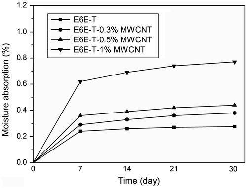
Resistance to moisture present in the service environment is an important property for ICAs. Moisture may decrease their adhesive property or cause corrosion to component joints. MWCNT-modified LCE composite samples are subjected to 75 °C/~100% RH aging, and the effect is studied as weight gain over a period of time. The results obtained are plotted against time and presented in Figure . It is observed that the samples are almost unaffected by the moisture. As can be seen, there is a slight increase in weight till first 7 day and thereafter, the variation is almost never found. The moisture absorbed may be due to the added MWCNTs not completely adhered to E6E-T network. The results show that there is not even 0.8% increase of weight in the testing samples. Thus, these prepared composites are highly stable under environment aging. MWCNTs due to their small size and lower loading levels are totally engulfed inside the matrix and hence do not bind water molecules. In addition, as the MWCNT concentration increased to 1%, moisture absorption increases slightly. But considering the overall effect, it is pretty clear that these samples can withstand extreme conditions of heat and moisture.
3.6. Morphology observation
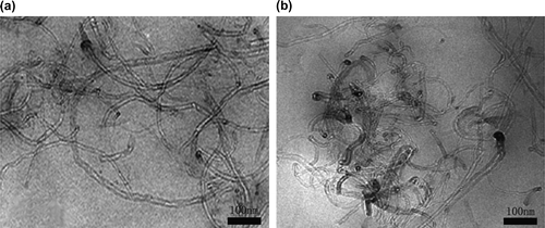
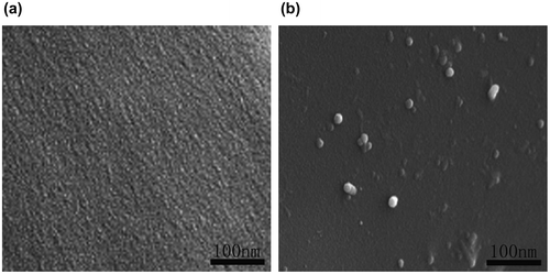
To analyze the state of the dispersion of the MWCNTs in the LCE matrix, TEM and SEM micrographs are taken for the composites. Figure shows the TEM micrographs of the composites, which reveal well-dispersed individual nanotubes in the matrix for all the composites. To some extent, slight agglomeration was observed for 1% MWCNT composite. Figure shows SEM micrographs of the fracture surface of the neat LCE and its composite (E6E-T-0.5% MWCNT) with a thin gold sputtering for better image quality. Interestingly, the added MWCNTs are found to be broken rather than pulled out of the surface, and most of them are embedded in and tightly held to the matrix, indicating a strong interfacial bonding between the epoxy matrix and the MWCNTs, which is responsible for the enhanced mechanical properties. Also, because of the smooth distribution, conductivity is established at lower MWCNT concentrations due to the formation of conductive channels which act as paths for charge propagation.
4. Conclusions
A series of novel ICAs based on MWCNT and LCE resin was prepared. TEM, SEM, DSC, POM, XRD, electrical conductivity measurement, and mechanical measurements were used to characterize the morphology, thermal, phase change, electrical, and mechanical properties of the prepared ICAs. The studies reveal that small size and uniformity of dimensions play an important role in defining the suitability of a material for being used as filler in LCE matrix. Excellent mechanical properties of the composites were obtained due to the load transfer from the LCE matrix to the tougher MWCNTs via interfacial adhesion between MWCNTs and epoxy as well as homogenous dispersion of MWCNTs in polymer matrix. Conductivity is established at a very low filler loading and conductivity value as high as 10−2 S cm−1 was obtained at a filler concentration of only 0.5%. The ICAs so formed not only show good adhesion but also show least effect of aging. The nematic phase was confirmed by POM and XRD measurements. DSC testing results showed that added MWCNTs did not show any major influence on typical curing peaks of epoxy. The overall properties of these samples establish their use as ICAs for electronic interconnections.
Acknowledgements
This work was financially supported by the Fundamental Research Funds for the Central Universities. (grant number 3142013094).
References
- Mir IA, Kumar D. Recent advances in isotropic conductive adhesives for electronics packaging applications. Int. J. Adhes. Adhes. 2008;28:362.10.1016/j.ijadhadh.2007.10.004
- Mir IA, Kumar D. Development of polyaniline/epoxy composite as a prospective solder replacement material. Int. J. Polym. Mater. 2010;59:994.10.1080/00914037.2010.504150
- Mir IA, Kumar D. Development of polypyrrole/epoxy composites as isotropically conductive adhesives. J. Adhes. 2010;86:447.10.1080/00218461003704519
- Ugur S, Yargi O, Pekcan O. Percolation and film formation behaviors of MWNT/PS nanocomposites. Procedia. Eng. 2011;10:1709.10.1016/j.proeng.2011.04.285
- Kim YS, Kim D, Martin KJ, Yu C, Grunlan JC. Influence of stabilizer concentration on transport behavior and thermopower of CNT-filled latex-based composites. Macromol. Mater. Eng. 2010;295:431.
- Lu J, Feller JF, Kumar B, Castro M, Kim YS, Park YT, Grunlan JC. Chemosensitivity of latex-based films containing segregated networks of carbon nanotubes. Sens. Actuators, B. 2011;155:28.10.1016/j.snb.2010.11.017
- Bose S, Khare RA, Moldenaers P. Assessing the strengths and weaknesses of various types of pre-treatments of carbon nanotubes on the properties of polymer/carbon nanotubes composites: a critical review. Polymer. 2010;51:975.10.1016/j.polymer.2010.01.044
- Ayatollahi MR, Shadlou S, Shokrieh MM, Chitsazzadeh M. Effect of multi-walled carbon nanotube aspect ratio on mechanical and electrical properties of epoxy-based nanocomposites. Polym. Test. 2011;30:548.10.1016/j.polymertesting.2011.04.008
- Sun L, Gibson RF, Gordaninejad F, Suhr J. Energy absorption capability of nanocomposites: a review. Compos. Sci. Technol. 2009;69:2392.10.1016/j.compscitech.2009.06.020
- Sahoo NG, Rana S, Cho JW, Li L, Chan SH. Polymer nanocomposites based on functionalized carbon nanotubes. Prog. Polym. Sci. 2010;35:837.10.1016/j.progpolymsci.2010.03.002
- Chou TW, Gao L, Thostenson ET, Zhang Z, Byun JH. An assessment of the science and technology of carbon nanotube fibers and composites. Compos. Sci. Technol. 2010;70:1.10.1016/j.compscitech.2009.10.004
- Tseng CH, Wang CC, Chen CY. Functionalizing carbon nanotubes by plasma modification for the preparation of covalent-integrated epoxy composites. Chem. Mater. 2007;19:308.10.1021/cm062277p
- Zhu J, Peng HQ, Rodriguez-Macias F, Margrave JL, Khabashesku VN, Imam AM. Reinforcing epoxy polymer composites through covalent integration of functionalized nanotubes. Adv. Funct. Mater. 2004;14:643.10.1002/(ISSN)1616-3028
- Jin ZX, Pramoda KP, Goh SH, Xu G. Poly(vinylidene fluoride)-assisted melt-blending of multi-walled carbon nanotube/poly(methyl methacrylate) composites. Mater. Res. Bull. 2002;37:271.10.1016/S0025-5408(01)00775-9
- O’Connell MJ, Boul P, Ericson LM, Huffman C, Wang YH, Haroz E, Kuper C, Tour J, Ausman KD, Smalley RE. Reversible water-solubilization of single-walled carbon nanotubes by polymer wrapping. Chem. Phys. Lett. 2001;342:265.10.1016/S0009-2614(01)00490-0
- Gojny FH, Wichmann M, Köpke U, Fiedler B, Schulte K. Carbon nanotube-reinforced epoxy-composites: enhanced stiffness and fracture toughness at low nanotube content. Compos. Sci. Technol. 2004;64:2363.10.1016/j.compscitech.2004.04.002
- Martin CA, Sandler J, Windle AH, Schwarz M, Bauhofer W, Schulte K. Electric field-induced aligned multi-wall carbon nanotube networks in epoxy composites. Polymer. 2005;46:877.10.1016/j.polymer.2004.11.081
- Li J, Lumpp JK. Carbon nanotube filled conductive adhesives for aerospace applications. Proceedings of the Aerospace Conference; 2007; IEEE; Big Sky, MT; 1–6.
- Cheng QF, Wang JP, Wen JJ, Liu CH, Jiang KL, Li QQ. Carbon nanotube/epoxy composites fabricated by resin transfer molding. Carbon. 2010;48:260.10.1016/j.carbon.2009.09.014
- Carfagna C, Amendola E, Giamberini M. Liquid crystalline epoxy based thermosetting polymers. Prog. Polym. Sci. 1997;22:1607.10.1016/S0079-6700(97)00010-5
- Brehmer M, Zentel R. Liquid crystalline elastomers- characterization as networks. Mol. Cryst. Liq. Cryst. Sci. Technol., Sect. A. 1994;243:353.10.1080/10587259408037775
- Lee JY, Song YW, Kim SW, Lee HK. Dielectric and molecular dynamic studies of sub-Tg by thermally stimulated current (TSC) analysis for liquid crystalline epoxy thermosets. Mater. Chem. Phys. 2003;77:455.10.1016/S0254-0584(02)00092-5
- Szczepaniak B, Penczek P, Warchalowska M, Rejdych J, Leszczynska I, Rudnik E. Liquid crystalline epoxy resins by polyaddition of diglycidyl ether of 4,4′-dihydroxybiphenyl and difunctional aromatic compounds. J. Polym. Sci., Part A: Polym. Chem. 1998;36:21.10.1002/(ISSN)1099-0518
- Lee JY, Jang JS. The effect of mesogenic length on the curing behavior and properties of liquid crystalline epoxy resin. Polymer. 2006;47:3036.10.1016/j.polymer.2006.03.009
- Castell P, Serra A, Galia M. Liquid-crystalline thermosets from liquid-crystalline epoxy resins containing bisazomethinebiphenylene mesogens in the central core: copolymerization with a nonmesomorphic epoxy resin. J. Polym. Sci., Part A: Polym. Chem. 2004;42:3631.10.1002/(ISSN)1099-0518
- Barclay GG, Ober CK, Papathomas KI, Wang DW. Liquid crystalline epoxy thermosets based on dihydroxymethylstilbene: synthesis and characterization. J. Polym. Sci., Part A: Polym. Chem. 1992;30:1831.10.1002/pola.1992.080300906
- Montserrat S, Flaqué C, Calafell M, Andreu G, Málek J. Influence of the accelerator concentration on the curing reaction of an epoxy-anhydride system. Thermochim. Acta. 1995;269–270:213.10.1016/0040-6031(95)02362-3
- Valentini L, Puglia D, Carniato F, Boccaleri E, Marchese L, Kenny JM. Use of plasma fluorinated single-walled carbon nanotubes for the preparation of nanocomposites with epoxy matrix. Compos. Sci. Technol. 2008;68:1008.10.1016/j.compscitech.2007.07.011
- Ribera D, Serra A, Mantecón A. Dimeric liquid-crystalline epoxyimine monomers: influence of dipolar moments on mesomorphic behavior and the formation of liquid-crystalline thermosets. J. Polym. Sci., Part A: Polym. Chem. 2003;41:1465.10.1002/pola.10690
- Lu MG, Shim MJ, Kim SW. Curing reaction and phase change in a liquid crystalline monomer. Macromol. Chem. Phys. 2001;202:223.

