Abstract
Optically isotropic liquid crystal (LC) mixture such as blue-phase LC and nanostructured LC composites exhibit the advantages of fast response time, high contrast ratio and wide-viewing angle due to the induced birefringence along the horizontal electric field. Utilizing this mixture, a novel single cell gap in-plane switching-type polymer-stabilized blue-phase transflective liquid crystal display by embedding the nanowire grid polarizer as a polarization-dependent reflective polarizer in the R region is proposed. This device can be used as a normal black mode without any quarter-wave plate or patterned in-cell phase retarder. Moreover, the transmittance is identical to the reflectance so that it will be suitable for single gamma driving. Detailed electro-optic performances, such as voltage-dependent light efficiency and viewing angle of the proposed device configuration, are investigated.
1. Introduction
Transflective liquid crystal displays (TR-LCDs) have been widely used in mobile devices, for example, cell phones, digital cameras and personal digital assistants, because of sunlight readability and low power consumption Citation1. On the liquid crystal (LC) configurations, single-domain and multiple-domain planar, twisted nematic, vertical alignment (VA), in-plane switching (IPS) and fringe field switching (FFS) modes have been explored Citation2. Among them, multi-domain VA, IPS and FFS are known to exhibit a superb viewing angle Citation3. Single cell gap IPS or FFS mode is an attractive approach for TR-LCDs to be capable of realizing wide-viewing angle, no gamma shift and stable color reproduction except the pointed out weakness of limited front contrast ratio Citation4. Moreover, IPS TR-LCDs are difficult to achieve, due to that this configuration usually requires either a quarter-wave plate Citation5 Citation6 or a patterned in-cell phase retarder Citation7 Citation8 to obtain a good dark state for the R mode. These approaches will cause issues such as higher manufacturing cost, thicker panel and sophisticated fabricating process.
To ameliorate these drawbacks, in this paper, we develop a single cell gap IPS-type polymer-stabilized blue-phase (PSBP) TRLCD configuration by embedding the nanowire grid polarizer (NWGP) under the pixel electrode and localized only in the R region as the polarization-dependent reflective polarizer. The transflective cell is divided into transmissive and reflective regions with the same LC profile without the need of any extra surface treatments. Such a configuration can achieve high light efficiency for both transmissive and reflective modes without using any achromatic quarter-wave plate (QWP) or patterned in-cell phase retarder laminated on the top polarizer. Moreover, the transmittance is identical to the reflectance, thus the single gamma voltage is matched for both the T and R regions.
2. Pixel structure and optical configuration
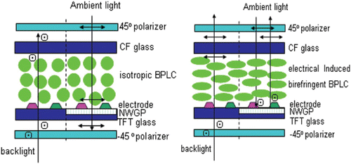
The cross-sectional view of the proposed IPS-PSBP-TRLCD is schematically shown in . The left and right sides, respectively, represent the black state and white states in the absence and presence of an applied field under crossed linear Nicolas polarizer. In the figure, the transmissive region is shown on the left side and the reflective region is shown on the right side. Based on the Kerr effect, the birefringence of PSBP LC is induced by the horizontal E-fields, which are generated by the protrusion electrodes, whose purpose is to lower the operation voltage of PSBP-LCD dramatically. The protrusion electrodes are fabricated by coating indium tin oxide (ITO) on top of the protrusions. To avoid sacrificing the aperture ratio, we set it to be transparent with an organic positive photoresist.
Figure 1. Schematic illustration of the proposed IPS-type PSBP-TRLCD. The left and right sides represent the black state and white states in the absence and presence of an applied field under crossed polarizer, respectively.
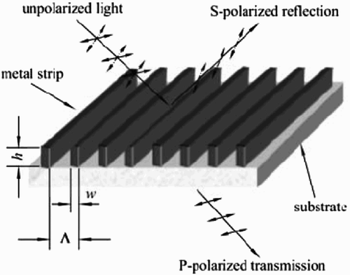
The grating structured wire grid polarizer (WGP) works like a polarization-dependent reflector that reflects the light with polarization parallel to the metal ribs, and transmits the other light component with polarization perpendicular to the grids Citation9. A schematic of the subwavelength aluminum wire grating is illustrated in . It consists of a series of fine parallel aluminum wires coated on a transparent substrate. When the period of the grating is far smaller compared with the wavelength of incident light, light polarized parallel to the metal wires is reflected, and light polarized perpendicular to the wires is largely transmitted. The most common explanation of the WGP is based on the restricted movement of electrons perpendicular to the metal wires. If the incident wave is polarized along the wire direction, the conduction electrons are driven along the length of the wires with unrestricted movement. The coherently excited electrons generate a forward traveling wave as well as a backward traveling wave, with the forward traveling wave canceling the incident wave in the forward direction. The physical response of the wire grid is essentially the same as that of a thin metal sheet. As a result, the incident wave is totally reflected, and nothing is transmitted in the forward direction. In contrast, if the incident wave is polarized perpendicular to the wire grid, and if the wire spacing is smaller than the wavelength, the Ewald–Oseen field generated by the electrons is not sufficiently strong to cancel the incoming field in the forward direction. Thus, there is considerable transmission of the incident wave. The backward traveling wave is also much weaker, leading to a small reflectance. Thus, most of the incident light is transmitted.
The direction of the metal ribs is perpendicular to the transmission axis of the top polarizer, and arranged at 45° with respect to the pixel ITO slit pattern. The fabrication of a NWGP typically involves imprint, demolding and pattern transfer using reactive-ion etching technology. More specifically, at first, a thin layer of aluminum is coated on a glass substrate, followed by a coating of a thin SiO2 layer on its surface to act as a hard mask for the later aluminum etching. Then, a layer of imprint resist is spin coated on the SiO2 surface, and a nanoimprint silica stamp with a predesigned wire grid pattern is used to replicate the pattern onto the imprint resist. After demolding the stamp, a series of reactive-ion etchings are applied to remove the residual layers (such as the patterned imprint resist and the SiO2 layers) on the aluminum surface and finally the aluminum layers in the replicated pattern. Thus, the wire grid pattern of the stamp is transferred to the aluminum layer.
For PSBP LC, the amplitude of the induced birefringence (Δ n i ) which is formed in a local region of the polymer network along the field direction is determined by following equation Citation10 Citation11:
To understand the polarization state of the light traveling through the PSBP LC layer easily, horizontal and perpendicular polarized lights are expressed with a straight line and circle, respectively, in . The basic working principle is described below.
When the applied voltage is lower than the threshold (V th), the LC system is optically isotropic at E=0. The linearly polarized light from the bottom polarizer keeps its polarization throughout the PSBP LC layer, and is blocked by the top crossed linear polarizer in the T part. For the reflective part, the incident light which passes the top polarizer keeps its polarization state through the blue-phase liquid crystal (BPLC) layer, and with its polarization perpendicular to the wire grid, the light can pass through the WGP and is absorbed by the bottom polarizer. Consequently, a dark state is achieved for both the transmissive and reflective modes.
As the applied voltage is larger than the threshold (V th), the molecular reorientations take place in the double-twisted cylinders. From macroscopic viewpoint, the effective optic axis of the induced refractive index anisotropy is along the electric field vector. Only the horizontal electric field contributes to the transmittance of the BPLC cell. As the external E-field reaches a saturation value, the induced phase retardation is functionally equivalent to a λ/2 plate both for the transmissive part and for the reflective part simultaneously. In the transmissive part, the polarization axis of the backlight passing through the bottom polarizer is rotated 90° by the BPLC layer, and it becomes parallel to the transmission axis of the top polarizer, and thus exits. As for the reflective part, the polarization axis of the incoming ambient light from the top polarizer is rotated 90° by the BPLC layer, and it becomes parallel to the wire grids, thereafter, is reflected back and further traverses the λ/2 LC layer by the WGP, gets another 90° rotation, and thus it can transmit through the top polarizer and the white state is realized. Actually, the mechanism for achieving a bright state in the reflective region is quite different. Both tilt and rotation effects of the LC directors in the R region jointly contribute to the optimal reflectance.
3. Electro-optic performances and discussion
To evaluate whether the above-mentioned principle is reasonable, the electro-optic performances such as voltage-dependent transmittance (V–T) curve, voltage-dependent reflectance (V–R) curve and iso-contrast plots for the above configurations are calculated. Simulation is performed by three-dimensional commercial simulation software Techwiz LCD (Sanayi System, Korea), which has developed a numerical solver to characterize electro-optical properties of the PSBP LC cell. In order to lower the on-state voltage obviously instead of the traditional inter-digital trip electrode, the protrusion electrode is adopted. In our simulation, the protrusion electrode is trapezoid shaped with the top width being equal to 1 μ m, the bottom width 2 μ m and the height 2 μ m, and the space between common and pixel electrodes is 4 μ m. The cell gap is 10 μ m. The physical properties of the used BPLC material are as follows: extraordinary and ordinary refractive indices of the host LC material and n
o
=1.4744(at λ=589 nm), parallel and perpendicular dielectric constants
and
, and the Kerr constant K=10 nm/V2 (at λ=630 nm).
Because the grating period (Λ) is far smaller than the wavelength, the traditional diffraction theory is not fit anymore. To include the NWGP into the optical modeling, effective-medium theory (EMT) is a candidate approach for modeling the microstructures. According to this theory, the whole structure behaves as if it were homogenous and equivalent to one birefringence film. Consider a one-dimensional grating composed of two materials with refractive indices n 1 and n 2 with duty cycle f (f=w/Λ, w is the width of the wire), under normal incidence, the effective indices for the TE (transverse electrical mode) and TM (transverse magnetic mode) polarizations of a subwavelength grating can be estimated from the zero-order EMT:
Here n 1 and n 2 are the refractive indices of the metal and the material filled in the gap, and the duty cycle f is set to be 0.5. The metal for wire grids is aluminum; it can be deposited between the aluminum wires by the oxide layer or overcoated by a transparent polymer as the protective layer to avoid direct exposure to the atmosphere; otherwise, a layer of Al2O3 forms rapidly on the aluminum wires, which will affect the polarization properties of the element. Generally, the refractive index n 2=1.5. As the thickness of the oxide layer increases, the transmission coefficient increases, but the extinction ratio decreases. During the reflective mode simulation, we have taken the refractive index wavelength-dependent character into consideration for the metal.
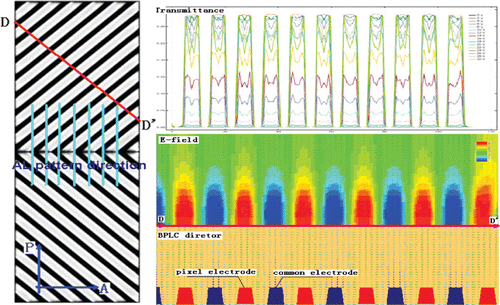
The left side of shows the simulation results of pixel brightness distribution at the voltage on state, and the pixels are designed to be a two-domain structure for decreasing color shift. The electrode directions of the two domains are cross-aligned at 45° with respect to the transmission axis of the top and bottom polarizers. The right side of shows the BPLC profile, E-field distribution and voltage-dependent transmittance cross-sectional view along the straight line DD’ labeled on the right side of .
Figure 3. Proposed structure brightness distribution at the voltage on state and the cross-sectional view of BPLC profile, E-field and voltage-dependent transmittance.
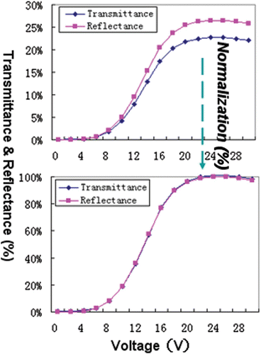
shows the simulated V–T and reflectance curves of the proposed cell structure. When the applied voltage reaches 22 V, the transmittance and reflectance reach a maximum value. After normalization, the V–T curve is almost identical to the V–R curve, which means that for both regions when using the same LC profile and driving approach, we can get the single gamma-modified gray level for both the transmission mode and reflection mode simultaneously.
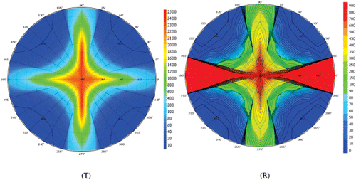
shows the iso-contrast contour plots of the T and R modes. Without using any compensation films, the T mode shows a 100:1 contrast ratio without grayscale inversion over the entire 60° viewing cone, and R mode shows a 10:1 contrast ratio without grayscale inversion over the entire 80° viewing cone. These viewing ranges are adequate for mobile displays using a small-sized LCD. However, we can see that the contrast ratio is extraordinarily high at the direction perpendicular to the aluminum wire. This is because the EMT for the NWGP is an ideal model and is not fit for the realistic situation very well. Actually, even if the use of the advanced nanolithography technology progresses, a pitch length of ∼ 100 nm cannot satisfy the reflective contrast ratio () exceeding 30:1. shows the wavelength-dependent transmittance and reflectance of the TE wave and TM wave of the NWGP with 150 nm pitch, 120 nm height and 0.4 duty cycle, which is simulated by the software Rsoft using the rigorous couple wave method. So, the actual contrast ratio in the horizontal direction is degrading to much less than 30:1. However, even this CR value is still fit to the requirement of the reflective mode.
4. Conclusions
In conclusion, we have proposed an IPS-PSBP-TRLCD with the same LC profile in free space without any rubbing treatment in the T and R regions. Our results show that this simple structure transflective display device exhibits high transmittance and reflectance, wide-viewing angle and fast response. By embedding the NWGP in the R region, well-matched V–T and V–R curves are obtained. This device is particularly attractive for mobile displays when continuous development of large-K LC materials can reduce the operation voltage to ∼ 10 V rms, which will be an important milestone because the device can be driven by amorphous silicon thin film transistors (a-Si TFTs), and widespread applications of blue-phase LCDs are foreseeable.
References
- M. Kubo, S. Fujioka, and T. Ochi, IDW’ 99, 183–186 (1999)
- Zhu , X. , Ge , Z. and Wu , S.-T. 2005 . J. Disp. Technol , 1 : 15 – 29 .
- Lu , R. , Zhu , X. and Wu , S.-T. 2005 . J. Display Technol , 1 : 3 – 14 .
- K. Okamoto; IDMC’ 03 (2003)
- Wu , S.-T. and Wu , C.-S. 1996 . Appl. Phys. Lett , 68 : 1455 – 1457 .
- Yu , C.-J. , Kim , J. , Kim , D.-W. and Lee , S.-D . 2004 . SID Symposium Digest , 35 : 642 – 645 .
- Park , J. B. , Kim , H. Y. and Lim , Y. J. 2005 . Jpn. J. Appl. Phys , 44 : 7524 – 7527 .
- Hirota , S. , Oka , S. and Itou , O. 2007 . SID Symposium Digest , 38 : 1661 – 1664 .
- Yu , X. J. and Kwok , H. S. 2003 . J. Appl. Phys. , 93 : 4407 – 4412 .
- Kikuchi , H. , Higuchi , H. and Iwata , T. 2007 . Proc. of Soc. Info. Display Symp. Digest , 38 : 1737 – 1740 .
- Ge , Z. , Rao , L. and Wu , S. T. 2009 . J. Display Technol , 5 : 250 – 256 .
