Abstract
Alignment failure sometimes occurs during the rubbing process because the rubbing cloth comes in direct contacts with the surface of the alignment film. A number of researches observed and evaluated the surface of the alignment film after the rubbing process had been reported. The real-time rubbing process has not been observed directly yet, though. In this study, the movement of the piles of the rubbing cloth during the rubbing process was observed with a high-speed camera. Furthermore, the relationship between the rubbing scratch on the alignment films and the movement of the pile was investigated. It was found that the movement of the pile affected the rubbing scratches.
1. Introduction
In the fabrication procedure for liquid crystal displays (LCDs), techniques to control the initial liquid crystal (LC) molecular state are very important. Several molecular alignment techniques have been developed such as the grating method Citation1, the photo alignment method Citation2, and the rubbing method Citation3–6, and some of them have been adopted for commercial LCD production. Among these methods, the rubbing method is still popular because of its simple process. Since the dawn of LC research, the rubbing method has been widely used. The advantages of the rubbing process are its short processing time and low cost and the viability of the large-scale LCD panel. At the same time, some drawbacks have been pointed out. First, during the rubbing process, a frictional electrostatic charge that strikes the damage to the thin film transistor on the LCD panel is induced. The friction between the rubbing cloth and the alignment film initially leads to anisotropy of the alignment film. Exceeding the friction force scratches the surface of the alignment film and causes a defect in the molecular alignment. Light leakage around the scratched alignment surface reduces the contrast ratio of the LCD. The defect in the molecular alignment is assumed to have been caused by the topological scratching of the alignment film surface by the rubbing cloth. Generally, however, evaluations of the surface of the alignment film have been done after the rubbing process by observing the LC alignment and/or the topology of the alignment film with an atomic force microscope (AFM) Citation7–18. The movement of the piles during the rubbing process was not observed.
An attempt was made to observe the movement of the piles during the rubbing process with a high-speed camera. To characterize the cloth material, cotton cloth, rayon cloth, and polyester cloth were used. The rubbing scratch on the alignment film was also observed via AFM. The relationship between the rubbing scratch on the alignment film and the movement of the pile was also investigated.
2. Experiments
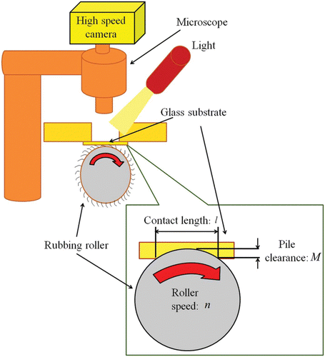
shows a schematic of the observation with a high-speed camera. As shown in the figure, the glass substrate was laid out on the rubbing roller. The rubbing roller of the rubbing machine is usually located above the substrate. In the experiment, however, the rubbing roller was located under the glass substrate to enable observation of the movement of the pile on the substrate with a high-speed camera (Fastcam-Neo, Photron) through a microscope (Opti-Photo, Nikon). The rubbing conditions were set at a roller speed n of 200 rpm and a pile clearance M of about 0.5 mm. M was calculated from the contact length l Citation19 as follows:
To improve the focus onto the movement of the pile, the stage was fixed and the roller speed was made lower than usual. In the experiment, the polyimide-type alignment film for the vertical alignment, PI-I (Chisso Petrochemical Co.), was spin-coated on the indium tin oxide film on the glass, and then baked at 220°C for 1 h. Then the surface of the alignment film was rubbed with three kinds of rubbing cloth: cotton, rayon, and polyester. lists the features of the three types of rubbing cloth. Cotton cloth being a natural fabric that is stiffer than rayon and polyester, it is expected to yield high anisotropy and strong azimuthal surface anchoring energy in the rubbing process. On the other hand, rayon and polyester are converted and/or synthesized fabrics, so soft rubbing can be expected with them. The rubbing conditions for the AFM experiment were set at an n of 500 rpm, an M of 0.5 mm, and a stage speed of 5 mm/s.
Table 1. Three types of rubbing cloth used in the experiments.
3. Results and discussion
3.1 Cotton cloth
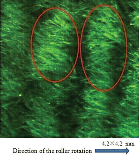
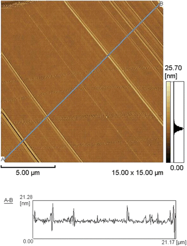
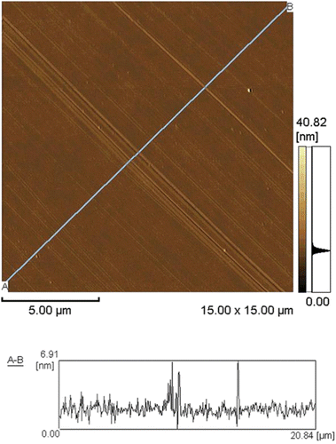
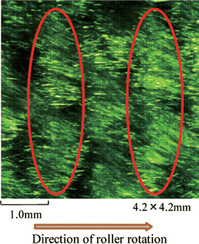
The movement of the cotton piles was observed with a high-speed camera, as shown in . The scanning zone of the high-speed camera was . shows an AFM image of the rubbed surface of the alignment film using the cotton rubbing cloth. The area of the scanning zone of the AFM image is
. shows the piles bending opposite to the roller rotation direction and aligned parallel to the substrate. Furthermore, the density of the piles seemed to be homogeneous. It was also recognized that the piles intersected with each other in some of the observed areas (denoted by the red ovals in ). The intersection of the piles might have been caused by the shape of the cotton pile, which is usually that of an elliptical cylinder and which makes it easy for the piles to be entangled. As a result, the piles are bundled and piled up. As shown in , the groove-shaped rubbing scratches were along the diagonal direction, which was parallel to the rubbing direction; whereas the pitch and depth of the rubbing scratches were irregular. The AFM image in the figure suggests that the irregularly entangled cotton piles rubbed more strongly than the homogeneously aligned cotton piles. The average depth of the groove apparently reached 7 nm, and deeply dug scratches (over 20 nm deep) were found, which caused light leakage in the LCD panel.
3.2 Rayon cloth
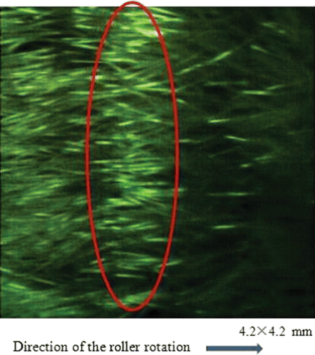
The movement of the rayon piles was observed using a high-speed camera, as shown in . It was confirmed that the piles were bending opposite to the roller rotation direction and were aligned parallel to the substrate, as in the snapshot of the cotton piles (). A comparison of and shows that the density of the rayon piles seems to have been controlled more regularly and homogeneously than that of the cotton piles (denoted by the red ovals in ), because rayon differs from cotton, which is a natural fabric, and the rayon was woven in an orderly manner. shows an AFM image of the rubbed surface of the alignment film using the rayon rubbing cloth. As shown in the figure, groove-shaped rubbing scratches were also found, and the rubbing scratches were shallower than the rubbing scratches with cotton. The average depth of the groove was apparently less than 3 nm, but 7 nm-deep scratches were found. This AFM experiment implies that the rubbing scratch can be reduced by leveling and combing the piles that are manufactured regenerated from cellulose fiber.
3.3 Polyester cloth
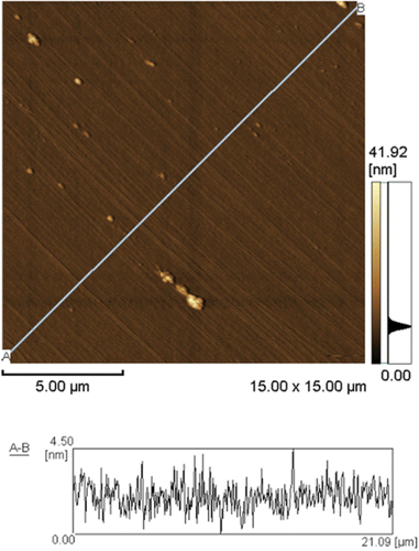
The movement of the polyester piles was observed using a high-speed camera, as shown in . It was confirmed that the piles were bending opposite to the roller rotation direction and were aligned almost parallel to the substrate, as in the snapshot of the cotton piles (). A comparison of and shows that the density of the polyester piles seems to have been controlled more regularly and homogeneously than that of the cotton piles. shows an AFM image of the rubbed surface of the alignment film using the polyester rubbing cloth. As shown in the figure, it was confirmed that the groove-shaped deep scratches were reduced and that the shallow scratches remained. The average depth of the grooves was less than 5 nm. As a result, the reduction of the light leakage was experimentally confirmed in the trial LCD sample. Unfortunately, some adhered debris were found on the alignment film. From the scanning electron microscopy experiment, it was analyzed that the adhered debris could have been a flake of the polyester pile. To reduce such debris, an appropriate aging process and rubbing condition may be required. In summary, it is suggested that the rubbing scratch be reduced using a well-prepared rubbing cloth to level and comb the artificial piles.
4. Conclusion
The movement of the piles of rubbing cloth was observed during the rubbing process with a high-speed camera. The relationship between the rubbing scratch on the alignment film and the movement of the piles was also investigated. It was found that the movement of the piles influenced the rubbing scratches that caused light leakage. It is important to control the density, homogeneity, and regularity of the pile alignment by leveling and combing the artificial piles. The materials of the cloth affected the relationship of the movement of the piles with the surface scratch on the alignment film. It is expected that the rubbing scratch problem can be resolved by choosing an appropriate combination of different types of rubbing cloth.
Acknowledgements
The authors thank Chisso Petrochemical Corporation for providing us with polyimide material.
References
- Nakamura , M. and Ura , M. 1981 . J. Appl. Phys , 52 : 210
- O'neill , M. and Kelly , S. M. 2000 . J. Phys. D , 5 : R67
- Mauguin , C. 1911 . Bull. Soc. Fr. Miner , 34 : 71
- Becker , M. E. , Kilian , R. A. , Kosmowski , B. B. and Mlynski , D. A. 1986 . Mol. Cryst. Liq. Cryst , 132 : 167
- Uchida , T. , Hirano , M. and Sakai , H. 1989 . Liq. Cryst , 5 : 1127
- Paek , S. H. , Durning , C. J. , Lee , K. W. and Lien , A. 1998 . J. Appl. Phys , 83 : 1270
- Seki , H. , Masuda , Y. and Uchida , T. 1996 . Mol. Cryst. Liq. Cryst , 282 : 323
- Kim , Y. J. , Zhuang , Z. and Patel , J. S. 2000 . Appl. Phys. Lett , 77 ( 4 ) : 513
- Sun , Y. and Wu , S.-T. 2003 . Jpn. J. Appl. Phys , 42 : L423
- Bechtold , I. H. , De Santo , M. P. , Bonvent , J. J. , Oliveira , E. A. , Barberi , R. and Rasing , Th. 2003 . Liq. Cryst , 30 ( 5 ) : 591
- Hong , H.-K. and Seo , C.-R. 2004 . Jpn. J. Appl. Phys , 43 ( 11 ) : 7639
- Zheng , W. , Underwood , I. , Macdonald , B. F. , Cole , R. J. , Vass , D. G. and Cole , R. J. 2004 . Mol. Cryst. Liq. Cryst , 412 : 237
- Oh , S. M. , Eom , T. Y. , Kim , S. J. , Lee , S. H. , Kim , H. Y. and Lim , Y. J. 2005 . Jpn. J. Appl. Phys , 44 ( 9 ) : 6577
- Zheng , W. J. 2007 . Mol. Cryst. Liq. Cryst , 479 : 3
- Yamahara , M. , Nakamura , M. , Koide , N. and Sasaki , T. 2007 . Liq. Cryst , 34 ( 3 ) : 381
- Lee , G. S. , Kim , J. C. and Yoon , T.-H. 2007 . Jpn. J. Appl. Phys , 46 ( 1 ) : 289
- Ma , J. , Hurley , S. , Zheng , Z. , Jin , B. and Yang , D.-K. 2009 . Liq. Cryst , 36 ( 5 ) : 487
- Son , K.-M. , Kim , S.-K. , Lee , J.-W. , Noh , S.-Y. , Kim , J.-P. , Park , S.-R. , Yang , J.-Y. , Yang , M.-S. , Kang , I.-B. and Chung , I.-J. 2010 . J. Soc. Info. Display , 18 ( 1 ) : 37
- Sato , K. Y. , Sato , K. and Uchida , T. 1992 . Jpn. J. Appl. Phys , 31 : L579
