Abstract
To improve the performance of blue fluorescent and green phosphorescent organic light-emitting diode devices, Merck developed novel green phosphorescent host and electron-transporting materials. The newly developed electron-transporting material improves the external quantum efficiency of blue fluorescent devices up to 8.7%, with an excellent lifetime. In combination with the newly developed host materials, the efficiency of green phosphorescent devices can be improved by a factor of 1.7, and the lifetime by a factor of 7.
1. Introduction
Although there has been constant progress in organic light-emitting diode (OLED) material development in recent years, the lifetimes of the blue fluorescent and green phosphorescent Citation1 Citation2 devices are not sufficient for all applications. To address this problem, new host and electron-emitting materials were developed. It was found, however, that the materials adjacent to the emission layer also play a critical part in OLED performance. Especially, the electron transport side has a strong impact on device efficiency, driving voltage, and lifetime. A fundamental connection was found between electron injection, electron transport, efficiency, and lifetime for blue fluorescent OLEDs and for the influence of charge balance within the device Citation3.
In R, G, and B side-by-side OLED devices, the electron transport layers are typically built as common layers. As the blue fluorescent pixel is typically the pixel with the shortest lifetime, the optimized electron transport setting for blue is also applied to the other colors. In this study, the influence of the host materials on green phosphorescent OLEDs for a given blue-fluorescent-lifetime-optimized electron transport layer stack was investigated.
2. Results and discussion
2.1 Tuning lifetime and efficiency in blue fluorescent devices using new electron transport materials
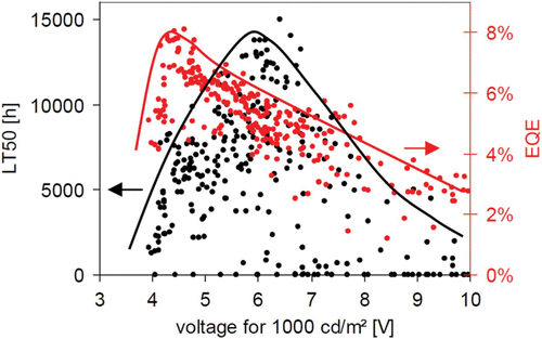
In blue fluorescent devices, it was found that the best EQE and the best lifetime cannot be achieved simultaneously Citation3 ().
Figure 1. Dependence of EQE (red) and lifetime (black) on the driving voltage for various ETL configurations (different ETMs, EILs, etc.). As all the devices had the same HTL and EML configurations, the voltage differences were due to the different electron currents.
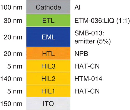
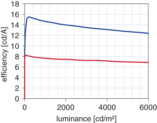
To achieve an excellent lifetime with good efficiency and driving voltage, the new electron transport material ETM-036 was developed. In combination with the Merck host SMB-013 and the deep-blue fluorescent emitter SEB-115, a Vop of 4.2 V, an EQE of 7.6%, and an extrapolated lifetime of 14,000 h at 1000 cd/m2 at a deep-blue Commission Internationale de l'Eclairage (CIE) y coordinate of 0.15 was achieved. With the blue emitter SEB-127 (CIE y=0.20), an EQE of 8.7% and an efficacy of 14.1 cd/A at 1000 cd/m2 were obtained in a similar setup ( and ).
2.2 Tuning lifetime, efficiency, and operation voltage in green phosphorescent devices using new host materials
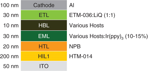
To evaluate the host materials for green phosphorescent devices, the device structure shown in was used.
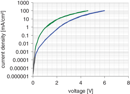
The hole injection layer (HIL) consists of a conventional Merck hole injection material. NPB (4,4′-bis (1 naphtyl-N-phenyl-amino)-biphenyl) was employed as the hole transport layer (HTL). The green phosphorescent emitter was fac tris(2-phenylperidine) iridium (Ir(ppy)3). While triple matrix material (TMM-A), a spiro-keton (bis(9,9′-spirobifluoren-2-yl)keton), is a pure electron-dominated host material, TMM-B is a more bipolar host, and TMM-C shows significant hole transport ().
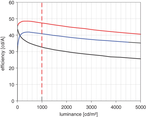
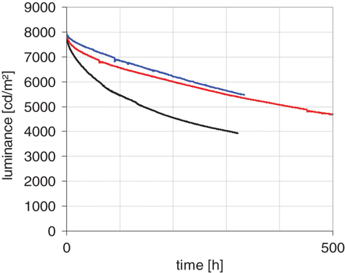
Both of the newly developed TMMs showed higher efficiencies as well as longer lifetimes. At 1000 cd/m2, TMM-B showed an efficacy of 47.4 cd/A and an approximated lifetime (LT50) of 47,000 h, and TMM-C showed an efficacy of 41.2 cd/A and a lifetime of 42000 h ( and ).
In the standard device setup with TMM-A, the emitter is mainly responsible for the hole transport. With the new matrices, especially with TMM-C, the matrix itself is capable of hole transport. Therefore, a high emitter concentration is no longer needed, allowing a wider variation in emitter concentration.
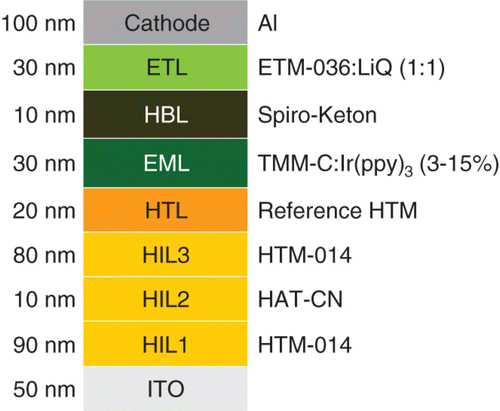
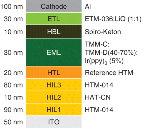
Shown in is the device setup for the following experiments, with an optimized hole transport material (HTM) thickness and an HTM material with a higher triplet gap than that of NPB.
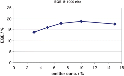
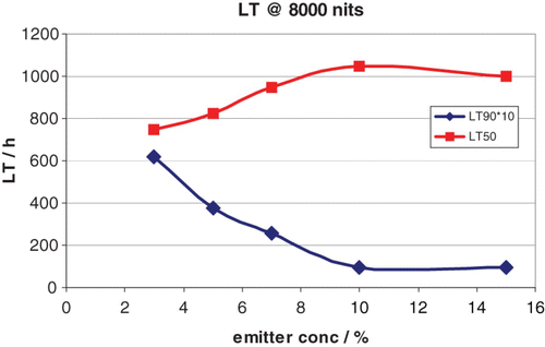
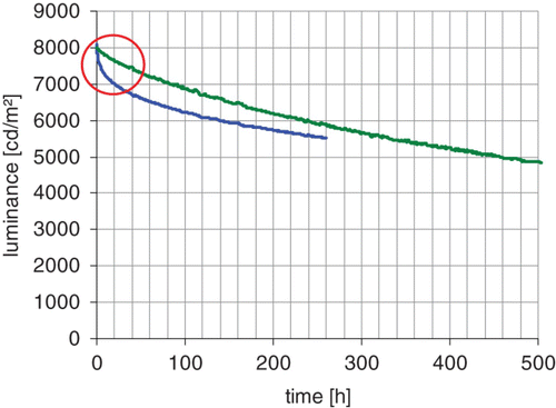
The optimum efficiency and lifetime for TMM-C were achieved at an emitter concentration of around 10% ( and ). The concentration variation showed only a moderate change in efficiency. The lifetime of LT50 showed a behavior very similar to that of efficiency; it can thus be assumed that the lower lifetime is mainly correlated to the lower efficiency in these devices ( and ). LT90, however, was strongly improved by the use of low emitter concentrations ( and ).
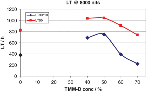
Another way of improving the device performance is by employing the mixed-matrix approach Citation4 Citation5. By adding a second matrix component (TMM-D), which will be mainly responsible for hole transport within the matrix, the charge balance can be tuned over a broad range. shows the device setup with a low emitter concentration of 5%.
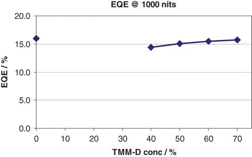
Mixed-matrix devices allow simultaneously high efficiency and very long lifetimes. At a 40-50% co-matrix concentration, a maximum lifetime for LT50 and very good values for LT90 were achieved, without overly sacrificing efficiency ( and ). Such values were obtained at a very low phosphorescent emitter concentration of only 5%.
3. Summary
The new electron material ETM-036, which is very well suited for blue fluorescent as well as green phosphorescent systems, was developed. The new generation of phosphorescent host materials significantly improves the lifetime and efficiency of the aforementioned systems without sacrificing the operation voltage. A further improvement in lifetime is possible by applying a co-host system using TMM-C and TMM-D, which also allow very low phosphorescent emitter concentrations.
References
- Baldo , M. A. , O'Brian , D. F , You , Y. , Silbey , S. , Thompson , M. E. and Forrest , S. R. 1998 . Nature , 395 : 151
- Baldo , M. A. , Lamansky , S. , Burrows , P. E. , Thompson , M. E. and Forrest , S. R. 1999 . Appl. Phys. Lett. , 75 : 4
- E. Böhm, C. Pflumm, F. Voges, M. Flämmich, H. Heil, A. Büsing, A. Parham, R. Fortte and T. Mujica, IDW’09, Miyazaki, Japan, OLED 1-2 (2009), 431–434
- Vestweber , H. , Gerhard , A. , Kaiser , J. , Heil , H. , Kroeber , J. , Pflumm , C. , Stoessel , P. , Joosten , D. , Buesing , A. , Fortte , R. , Parham , A. and Boehm , E. 2008 . IMID/IDMC/ASIA display ’08 Technical Digest , : 925
- Kondakova , M. E. , Pawlik , T. D. , Young , R. H. , Giesen , D. J. , Kondakov , D. Y. , Brown , C. T. , Deaton , J. C. , Lenhard , J. R. and Klubek , K. P. 2008 . J. Appl. Phys , 9 : 104
