Abstract
Electrowetting displays combine high transmittance, bright colors, and low-power consumption. Like liquid crystal displays, they also allow all modes of operation: reflective, transmissive, transparent, and transflective. This paper reports the latest improvements related to the main optical component, the light-absorbing oil film, and its influence on the display properties. A new set of black mixtures was developed with improved dyes that allow high optical efficiency. High-contrast transmissive displays were fabricated with good switching properties. Moreover, the reflective displays show very low oil backflow levels, which are beneficial for power reduction. The reliability of such new oils was also studied, considering their bleaching and miscibility properties.
1. Introduction
The electrowetting display technology is based on the contraction of a colored oil film driven by the motion of a second transparent, high-surface-tension polar liquid called “electrolyte”, controlled by an electric field Citation1–3.
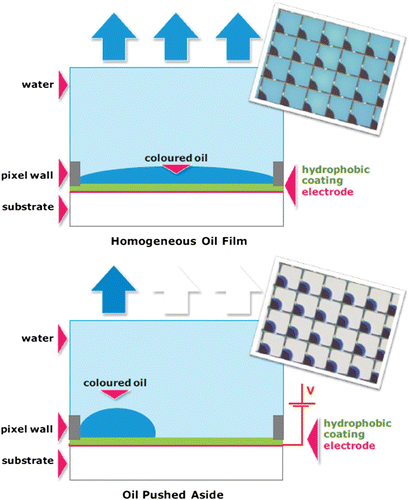
The display principle is explained in . The colored oil film/electrolyte “liquid stack” is enclosed in a pixel structure grid that prevents any contact between the oils of two adjacent pixels. In the off-state, the colored oil film covers the entire pixel surface and absorbs light, and the pixel is in the darkest state. The surface of the pixel is covered by a thin fluoropolymer layer that works as an electrical insulator and a hydrophobic surface; its low surface energy allows the oil film to wet while the electrolyte is repelled. The transparent state of the pixel is achieved by applying an electric field across the liquid stack. Initially, the electric field induces the breaking of the oil film, and the electrolyte comes in contact with the hydrophobic surface, forming a three-phase contact line. The degree of wettability depends directly on the strength of the electric field, as indicated in the Young–Lippmann equation Citation1, and this electrowetting effect results in the contraction of the oil film into a droplet shape. The initial oil film's absorbance and its maximum contraction level define the contrast ratio of the display.
2. Materials
The colored oil film is one of the critical materials in electrowetting displays and is definitely the most important with respect to the optical properties. It consists of dyes dissolved in an organic solvent that can match the required absorbance and color points. Here, the focus will be on black mixtures, to enable full-color electrowetting displays. Black oils represent the most challenging oil formulations because they must absorb the whole visible spectrum. Moreover, the absorbance level required, especially for the transmissive mode leads to a high solid content in the formulation. Consequently, in addition to the selection of the dyes for formulating the black oil, the dye–dye interactions can also affect the optical and switching performances of the display.
As can be seen in the pixel configuration illustrated in , the oil film thickness influences both the electrical and optical characteristics of the display. The voltage needed to break the oil film, called “threshold voltage”, depends on the oil film's thickness and dielectric properties. The optical properties of the oil film are described by the Beer–Lambert law, where the optical density (or absorbance) is equal to the concentration of the absorbing dyes times, the extinction coefficient of the dyes times, and the thickness of the film. Due to the low oil thickness, a high figure of merit (optical density per unit length; ) is required to produce a high-contrast-ratio display. In this paper, the oil film thickness is typically either 4 or 5 μ m.
The selection of the dye material for display applications is a critical process and requires a good knowledge of the electrowetting effect and of the display technology. The dye screening first focuses on the optical and chemical properties to ensure good solubility, high optical density, and a specific color point, eg. a neutral color point in the case of black oil (like the CIE Standard Illuminant D65, the average daylight, with a correlated temperature of approximately 6500 K).
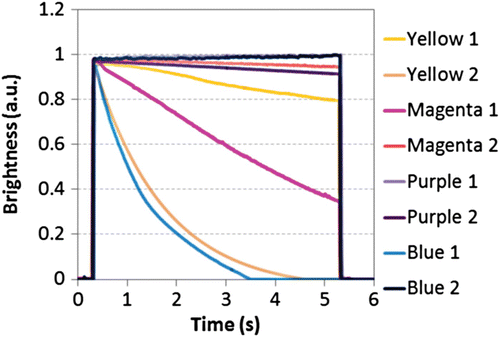
Dyes are also selected according to their impact on the electrowetting properties of the pixel. The addition of dyes to the oil film can alter the electrowetting operation by introducing an undesired effect called “backflow” Citation3. This effect is the tendency of the oil to flow back into the pixel at a constant voltage. This leads to a reduction of the oil-level contraction, and consequently, to a decrease in pixel aperture. A strong dependence on the dye's chemical nature has been observed. shows the optical pixel response to an identical electrical stimulus for various colored oils. The backflow level can vary significantly, from complete pixel closing to no brightness loss. As shown in , the backflow level shows no structural dependence on the color; i.e. for different dyes of the same color, different backflow behavior can be observed. This highlights the influence of the molecular structure on the backflow level. The choice of the molecule is therefore crucial when optimizing for electrowetting display applications.
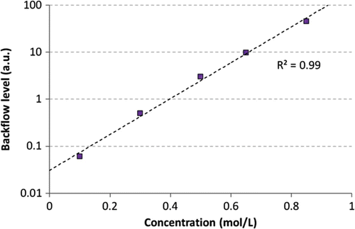
The concentration of dyes in the absorbing liquid also affects the level of backflow. In , the backflow level is plotted as a function of the concentration of a purple dye. Here, the backflow level is calculated from the optical measurements; the loss of brightness is related to the loss of oil contraction. The higher the value is, the faster the oil spreads back into the pixel. As shown in , the backflow level is exponentially dependent on the dye concentration while the absolute magnitude of the backflow will vary from dye to dye.
The backflow effect has an impact on both the switchability and the power consumption of displays, as mentioned in Citation3. Electrowetting displays can be operated at a battery-saving usage mode, by adapting the refresh rate to the display content. For example, when the display operates in the static reading mode, the refresh rate of the display can be lowered accordingly, and thus, the power consumption is reduced because it scales with the refresh rate. This driving technique is called “dynamic adaptive frame rate driving” and can be implemented only with a stable pixel optical response during the frame time, to avoid display flickering. As black oil with a high backflow requires a higher refresh rate, a high backflow limits the window for the dynamic adaptive refresh rate. As such, a low backflow level is desired to achieve the lowest possible refresh rate.
Another dye screening step focuses on the lifetime properties and particularly the oil film stability at a certain temperature as well as the resistance to sunlight exposure (optical bleaching according to international standards). It must be proven that the oil film's optical properties remain unchanged after temperature and bleaching tests. As already mentioned, the backflow effect is strongly dependent on the chemical structure of the dyes. Consequently, ensuring the integrity of the dye molecules during lifetime operation is key to maintaining the electro-optical properties of the display. In the case of bleaching tests, not only does the display contrast ratio have to stay unchanged as a result of the stable dye chromophores; the backflow also has to stay minimal as a result of minimal molecular degradation during sunlight exposure.
Finally, the last dye screening step focuses on the integrity of the two liquid phases. The “electrolyte” phase and the colored oil phase remain in contact during the display lifetime; and as such, their miscibility needs to be minimized. The selection of the dyes and their solvents are therefore crucial in maintaining the integrity of the two liquid phases and keeping the electrowetting operation stable during lifetime operation.
In this paper, based on the screening methods previously described, improvements of black oils for all modes of electrowetting displays are reported, with details on their impact on overall display performance. It is noted that because the optical light path in the transmissive mode is double that of the reflective mode, the first case is more challenging in terms of the optical display performance.
3. Experiment
Test displays were studied to evaluate the performance of black oils. A transparent conductive layer deposited on a glass substrate was covered by a submicron layer of the commercially available Teflon AF1600 fluoropolymer. A pixel grid structure made of SU8 negative photoresist was then put on top of the hydrophobic layer, creating pixels. The displays were finally filled with the investigated oils and a customized electrolyte, and then closed Citation4.
The oil viscosity was measured using a Brookfield “DVII+ Pro” viscometer with a small cone/plate adapter at various temperatures, from about 0 to 50°C. The optical properties of both the oils and the displays were measured using an ultraviolet-visible (UV-Vis) spectrophotometer (Perkin Elmer Lambda 850). A cuvette with a 10 μ m path length was used to determine the oils’ spectra. The oil stability at low temperature was evaluated for 24 h at −35°C. After filtration at , the oil degradation was quantified by evaluation of the optical properties. The stability of the oils at high temperature was tested in situ by storing and operating the panels in a 60°C oven. The optical and switching performance of the displays were measured at various points during the test.
The bleaching resistance of the oil was evaluated in situ, following the standard method IEC-60068-2-5, which applies to the final product, in this case, the display. The displays were kept under accelerated sunlight conditions for 10 days, with the temperature set at 42°C. The electrical response of the displays was characterized via video acquisition followed by image treatment. The threshold voltage, optical response (white area (WA)) at −20 V, and backflow level (at −20 V for 5 s) were measured. The WA% is the pixel area percentage where the oil has been removed for light transmittance. The backflow level is expressed as the loss of WA% per second.
The influence of the temperature on display response times was studied by measuring the display operation in a climate chamber using a calibrated photodiode. The temperature was set from −40 to 70°C with a 10°C step. The response time is defined herein as the sum of the rise and fall times. These are the times for opening or closing the display pixels when transitioning from 0 to −20 V and back to 0 V.
The miscibility between the two liquids was evaluated using an internal procedure. The two liquids were made to come in contact with each other at an elevated temperature (60°C) to allow miscibility. This could accelerate the miscibility process that could occur in the display due to the contact between the two liquids. The miscibility of the dyes into the electrolyte phase was monitored via optical measurement using a UV-Vis spectrophotometer; the dyes dissolved in the electrolyte were first extracted and were then redissolved into the oil solvent for measurement.
4. Results
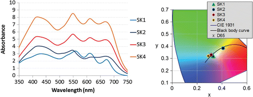
Four different black oils were investigated in this work: SK1, SK2, SK3, and SK4. SK1 was originally developed for reflective displays and is used as a reference black. A new set of dyes was used to formulate SK2, SK3, and SK4. SK1 and SK2 have similar optical properties suited for reflective-mode displays, while SK3 and SK4 were developed for transmissive electrowetting displays. The solid content of these oils are 25%, 13%, 22%, and 32%, respectively. The average optical densities (in the visible wavelength range) of SK1/SK2, SK3 and SK4 in 10 μm are about 3, 5, and 7.5, respectively (). The color points of the black oils for single pass are also shown in . It is worth noting that in some cases, such as SK1 and SK3, it is possible to achieve about two times more absorbance while having similar weight solid contents. Black oils with optical densities as high as 10 will be part of further investigation.
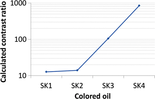
As shown in , the modeled contrast ratio for a transmissive display increases from ∼15 for SK1 and SK2 up to ∼800 for SK4. This has been calculated with a single light pass through the oil film, and assuming a black mask in the areas not covered by the oil, such as the pixel walls. Clearly, this more than 50 times improvement makes the technology a competitive option for transparent and transmissive applications, in addition to the reflective applications already targeted in the past. In fact, in the case of reflective displays, which also account for double light pass, the optical density of SK1 and SK2 is already enough to guarantee a high contrast ratio of above 10; in this case, the contribution of the oil to the black level is less than the anti-reflection coating at the first air/glass interface.
Figure 5. Calculated contrast ratio of the displays filled with the SK oils, according to their absorbance spectra.
The switching data at room temperature is shown in . The test displays filled with SK1 and SK2 showed similar threshold voltages and WAs. At similar optical performances, however, SK2’s backflow level was reduced more than 2.5 times compared with that of SK1. This demonstrates the superiority of the new set of dyes for electrowetting operations. Thus, the backflow level of SK1 can be maintained for oil with a higher optical density (SK4). SK4’s threshold voltage is slightly higher (and its WA is slightly lower). This could be a consequence of the high solid content.
Table 1. Switching properties of the SK oils.
No optical bleaching was observed for the displays filled with SK4, as shown in . The changes in the reflectance spectrum after bleaching were small and, in fact, resulted in a color point variation below 1 JND (just-noticeable difference, corresponding to Δ E=2.3 in the CIELab color system) during the 10-day accelerated test. For the displays filled with SK1, the color point difference increased until 2 JND during the test, a higher value with respect to SK4 but possibly still fully acceptable for display applications. The stronger bleaching resistance of SK4 compared with SK1 could be due to the new set of dyes used for SK4, or to its higher solid weight content. Further measurements on displays filled with SK2 and SK3 are required to establish how the new set of dyes impacts the bleaching resistance.
Figure 6. Change in the reflectance spectra and color points in terms of JND of the test displays filled with the SK oils during the bleaching test, according to the standard.

As already mentioned, SK4 has the largest solid content (32%). As dye solubility is generally temperature-dependent, a new solution with a 42% dye solid content and a higher optical density was made. This oil contains the same dyes as SK4, in similar proportions. At a low storage temperature (−35°C), the color point of this oil does not vary more than 0.11 JND. This measurement shows the stability of SK2 and SK4 at a low temperature.
The oil stability at a high temperature was evaluated in situ by storing and operating the displays at 60°C. Test displays filled with SK2 and SK4 were tested. No optical degradation was observed with color point differences of 0.65 and 0.92 JND for SK2 and SK4, respectively, for 400 h. The switching performances were studied for 230 h. The threshold voltages for both the SK2 and SK4 displays showed variations smaller than 1 V. For both the SK2 and SK4 displays, the backflow levels slightly increased but remained below the maximum specifications of 5% WA loss/s at 1 and 4%, respectively.
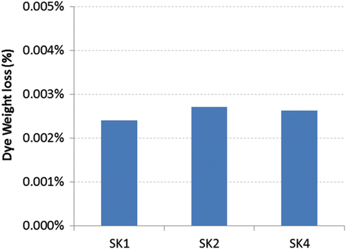
The oil/electrolyte miscibility was measured for SK1, SK2, and SK4. The dye weight percentage loss was quantified by taking into account the higher electrolyte to oil volume ratio from this experiment and comparing this with the one in a typical display. These measurements were performed after 120 h at 60°C. Less than 0.005% of the dyes were dissolved in the electrolyte phase (). Consequently, the display contrast decreased by about less than 0.5%. This means that the displays filled with SK4 showed a contrast ratio decrease from about 850:1 to 845:1 in the worst scenario.
Figure 7. Dye weight loss percentage during the miscibility test for the SK oils with custom electrolyte.
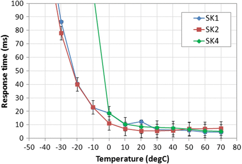
The displays filled with SK1, SK2, and SK4 showed response times below 25 ms at the 0–70°C temperature range (). For lower temperatures, the higher solid content of SK4 had an impact on the display performance. This is related to the higher viscosity measured for SK4 compared with SK2, especially at a low temperature (). Reducing the viscosity increase at a lower temperature, while maintaining high optical performance is part of the authors’ current program for further improving the dyes for electrowetting displays.
5. Conclusions
New dyes for electrowetting displays were developed. These dyes have superior optical densities and as such enable a 50-fold contrast ratio improvement. This means that electrowetting displays can be applied competitively in the transparent/transmissive mode, in addition to reflective-mode operation.
The developed dye materials undergo extensive material testing before being released for use in displays. This enabled the introduction of a black oil with a high contrast ratio for transmissive displays operating a 0–70°C temperature range. Furthermore, black oils are available, fulfilling all the display specifications for the reflective mode at a wide temperature range.
Acknowledgements
The authors would like to thank all their colleagues from Samsung Netherlands R&D Center and from Samsung LCD Research Center in South Korea, as well as their dye partners, for their support.
References
- Hayes , R. and Feenstra , B. J. 2003 . Nature , 425 : 6956 (doi:10.1038/nature01988)
- Giraldo , A. , Aubert , J. , Bergeron , N. , Derckx , E. , Feenstra , B. J. , Massard , R. , Mans , J. , Slack , A. and Vermeulen , P. 2010 . J. SID , 18/4 : 317
- Giraldo , A. , Massard , R. , Mans , J. , Derckx , E. , Aubert , J. and Mennen , J. 2011 . SID 2011 Display Week Proceedings , 114 ( 10.3 )
- Massard , R. , Giraldo , A. , Mans , J. , Vermeulen , P. and Hampton , M. 2011 . Eurodisplay 2011 Proceedings ,
![Figure 9. SK oils’ viscosities for the temperature range [−0.5°C, 50°C].](/cms/asset/60f415ba-afe9-4074-bc31-8f21ed184209/tjid_a_751939_o_f0009g.jpg)