Abstract
A stereoscopic three-dimensional (3D) system using a polarization rotator is proposed. The polarization rotator converts the polarizations of images from different eyes in temporal multiplexing. A novel fast nematic liquid crystal mode is also proposed. The new liquid crystal mode has a fast response time and a high contrast, and is thus a good candidate as a polarization rotator. The proposed 3D system uses only passive polarized glasses, which are more convenient, lightweight, and low-cost than what? In addition, the polarization rotator can be applied to current two-dimensional displays and can become 3D-capable displays.
Present market trends in three-dimensional (3D) displays show a steady growth in adoption, especially of 3D televisions (TVs). It is predicted that 3D TVs will follow high-definition televisions (HDTVs) as the third-generation TVs Citation1. Stereoscopic displays by presenting two offset images separately to the left and right eyes of the viewer have been the main technology in 3D TVs Citation2. Such displays have several advantages over other 3D technologies. For instance, they can be built based on the conventional television technology, can support multiple users, have low crosstalk, and are inexpensive. To realize the stereoscopic 3D effect, the system could be combined with a pair of active shutter glasses based on the temporal sequencing method, or with a pair of passive polarized glasses based on the spatial sequencing method. However, the passive polarized glasses have the advantages less weight, cost, and power consumption.
In this study, a stereoscopic 3D display that uses a polarization rotator is proposed. The polarization rotator can be relied on for fast liquid crystal technology. With it, the shutter glasses can be replaced by passive polarized glasses, which viewers will find more desirable. A fast liquid crystal mode is also developed for the polarization rotator. It showed a fast response time and a high contrast.
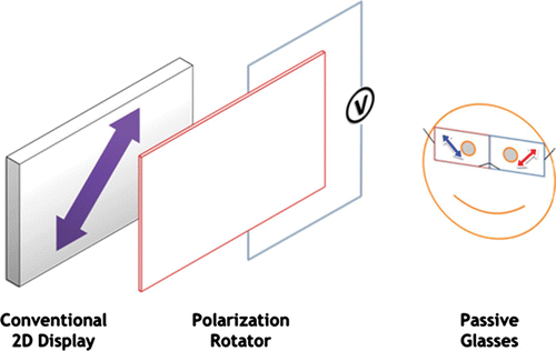
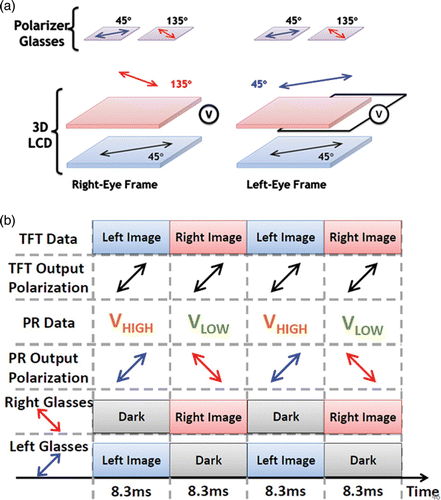
The proposed 3D system is shown in . It comprises a conventional two-dimensional (2D) display, a polarization rotator, and a pair of passive polarized glasses. The polarization rotator is placed in front of a conventional 2D display. It can rotate the output light polarization of the 2D display, either parallel or orthogonal to its original polarization. Thus, the viewer can receive images from different eyes by wearing a pair of passive polarized glasses. shows the detailed polarization of the entire system. The 2D display is assumed to have a linear 45° polarization. When no voltage is applied to the polarization rotator, it rotates the polarization from 45° to 135°. With the same polarization direction glasses, the right eye can see the image content while the left eye cannot. In contrast, if a voltage is applied, the polarization rotator becomes transparent, which leaves the polarization unchanged. In this case, the left eye can see the image while the right-eye image is blocked by crossed polarizers. The polarization rotator operates normally brightly and normally darkly for the right and left eyes, respectively. The timing of the system is shown in . The display should be capable of displaying alternate left- and right-eye images at a high update frequency (≥120 Hz) to avoid visible flicker. Moreover, the polarization rotator should be synchronized with the corresponding frame.
The polarization rotator must have a fast response time, high transmittivity, and a high contrast for both the crossed polarizers (which are normally bright) and the parallel polarizers (which are normally dark). It can actually use the fast liquid crystal mode. Previously, the authors proposed a fast response time display that uses the transient response of a reversely doped twisted nematic (TN) cell, which is called the stressed splay twisted (SST) mode Citation3. However, such transient response bounce has bad contrast when it is under normally black operation. On the other hand, the optically compensated-for bend (OCB) mode has been studied for a long time. It has been proved to have a fast response time and a wide viewing angle Citation4. However, its drawback is that the liquid crystal molecules are actually more stable in the splay deformation when no voltage or only a small voltage is applied. A very large voltage (>10 V) or a special driving scheme must be applied to transform the liquid crystal molecules from the splay state to the bend state. In addition, such \normalmarginpar
transformation is a random process and depends on the nucleation, which is difficult to control Citation5. Some researchers have proposed the use of a liquid crystal polymer to stabilize the low-voltage bend state Citation6–9. Although other fast liquid crystals, such as ferro-electric liquid crystal (FLC) and blue phase LC, have been invented, the use of the nematic liquid crystal is still the mainstream in the liquid crystal industry.
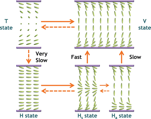
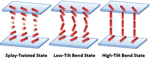
In this study, a new fast liquid crystal display (LCD) mode called the π-SST mode is proposed. It combines the SST and OCB modes. shows the operation of a normal OCB display. The OCB display is stable in the splay state (the H state) when no voltage is applied. When the applied voltage exceeds the critical level (about 2–3 V), the liquid crystal molecules are transformed into the bend state (the V state) through the symmetric splay state (the Hs state) and the asymmetric splay state (the Ha state). If this critical voltage is removed, the bend state is first transformed into the splay-twisted state (the T state) and then finally decays slowly back to the original splay state (the H state). As the transition between the bend state and the splay-twisted state is fast, the OCB can be modified by adding a chiral dopant into the liquid crystal. Thus, the splay-twisted state, rather than the splay state, becomes stable when no voltage is applied. shows the orientation of the liquid crystal molecules with different applied voltages. When no voltage is applied, the π-SST mode is in the splay-twisted state, and the liquid crystal undergoes both the splay and twist deformations. When the applied voltage reaches the critical level, the liquid molecules are transformed to the low-tilt bend state, similar to that of the OCB display. When the applied voltage is much larger than the critical voltage, the liquid crystal molecules are further transformed into the high-tilt bend state, wherein the twist deformation is almost completely gone, leaving only the bend deformation. The π-SST mode is a good candidate as a polarization rotator. Compared with the normal SST mode, it has a fast response time and a high contrast for both normally bright and normally dark operation. Another advantage is unlike the conventional OCB mode, for the π-SST mode, the transformation from the splay-twisted state to the bend state is continuous, as these two states have the same boundary condition, i.e. nucleation is not required. The π-SST mode also has a slightly faster response time and a better contrast than the OCB mode, which is shown in .
Table 1. Measured response time and contrast of the π-SST and OCB modes.
To verify the predictions, a π-SST-mode LC cell was fabricated. A homogeneous polyimide JALS-9203 that was provided by JSR Corporation was used to align the liquid crystal. The pre-tilt angle was about 2° after mechanical rubbing. The cell gap was 5 μm and was assembled with a parallel alignment structure. A left-handed dopant, S-811, was added to the liquid crystal MLC-6080 with a 12.35 pitch. Both materials were provided by Merck Corporation. The Δ n of the liquid crystal MLC-6080 was 0.2024. Then, the cell was filled with the liquid crystal. An OCB-mode cell was also made for comparison. The response times and contrast ratios of both cells with crossed polarizers (Polarization 1) and parallel polarizers (Polarization 2) were measured and are shown in . The longest response time in both cases was 1 ms, which is satisfactory.
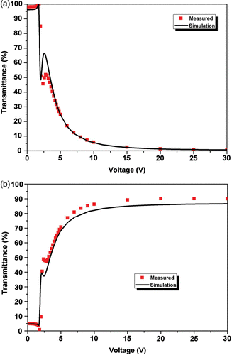
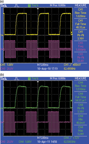
The polarization rotator actually requires only two states: the transparent state and the rotational state. The rotational state can be chosen either using the splay-twisted state or the low-tilt bend state. Both cases work fine, and differ only in their driving waveforms. If the splay-twisted state is chosen to be the rotational state, the optics of the splay-twisted state should be optimized, i.e. its cell retardation. In addition, zero voltage should be applied to the rotational frame. shows the measured transmission voltage curve (TVC) of the π-SST cell at a 550 nm wavelength. When the applied voltage is about 3 V, which is the critical voltage, there is a small bounce in the TVC curve, which indicates that the splay-twisted state is transformed into the low-tilt-bend state. However, as the intermediate gray levels are unnecessary for the polarization rotator application, it is fine to have a rough TVC characteristic. In the other case, if the low-tilt bend state is chosen to be the rotational state, the π-SST cell acts like a normal OCB, except that the splay-to-bend transformation at the start is eliminated, which means that the π-SST mode is still more preferable than the normal OCB cell mode. In this case, a holding voltage should be applied to the rotational frame. shows the captured response time waveform in both cases. The driving waveform is composed of 30 Vpp 1 kHz square-wave pulses. The response times with and without the holding voltages are 1 and 1.5 ms, respectively. In the demo, the splay-twisted state was chosen as the rotational state. The splay-twisted state has the advantage of having no holding voltage, although it has a slightly slower response time than the low-tilt bend state.
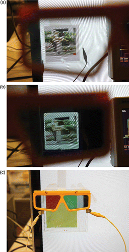
A 4 in. polarization rotator was successfully fabricated and placed in front of a commercial 22 in. 2D LCD monitor, as shown in . and shows the left-eye and right-eye images, respectively. A small color square was placed at the bottom right of the picture to indicate either the left- or right-eye picture. The red square corresponds to the left-eye picture, and the green square, to the right-eye picture. The frame rate was 90 Hz, which was limited by the LCD monitor. As the polarization rotator has but a single pixel, the simple direct-driving scheme can be applied to it. The polarization rotator was successfully separated to have a mixed red-green color, as shown in . A conventional 2D picture can also be shown when the user is not wearing the polarizer glasses.
Figure 7. (a) Left-eye images, (b) right-eye images, and (c) pair of red and green stereoscopic images.
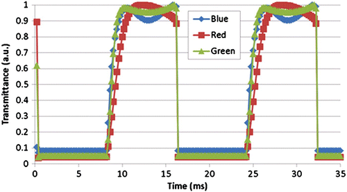
The crosstalk of the proposed 3D system comes from three sources. The first source is the light leakage at the dark state of the polarization rotator. The second source is the light leakage during the switching of the polarization rotator. The third source comes from the nature of the liquid crystal display, as the liquid crystal display is a “sample and hold” system. The second and third problems can be eliminated by the blinking backlight for the black insertion. When the display images are changed from right-eye to left-eye or from left-eye to right-eye, the backlight is turned off. As a result, the contrast of the polarization rotator becomes the main issue. In addition, the color dispersion of the π-SST display makes the crosstalk appear in red, green, and blue colors. plots the measured response of a π-SST display with different wavelengths: red (650 nm), green (550 nm), and blue (450 nm). The green color performed best and the blue color the worst. Similar to the case of the OCB display, the color dispersion can be reduced by increasing the pre-tilt angle of the substrates or placing the what? In between a pair of wide-viewing-angle films with discotic layers Citation10. The crosstalks of the entire 3D system with the π-SST mode and the OCB mode were measured and are listed in . Using the π-SST mode as the polarization rotator has the advantage of a lower crosstalk than in the OCB mode. The asymmetric crosstalk of the left and right eyes is due to the different contrasts in the normally bright and normally dark operations.
Table 2. Measured crosstalk of the proposed 3D system using the (a) π -SST and (b) OCB modes as the polarization rotators.
In conclusion, a 2D/3D switchable display that uses a fast liquid crystal polarization rotator was demonstrated. The polarization rotator enabled the replacement of the shutter glasses with passive polarized glasses, which viewers find more desirable. Such a polarization rotator can be applied to the current 2D display and can become 3D-capable. The proposed 3D system has a full resolution and a simple configuration with only one switching element. A fast liquid-crystal mode, called π-SST, was also demonstrated. The proposed π-SST mode was found to be good for the polarization rotator. A 4 in. demo unit and its driver were successfully fabricated.
References
- Kawai , T. 2002 . Displays . 23 ( 1–2 ) : 48 – 56 .
- Woods , A. 2009 . Inf. Disp. , 25 ( 7 ) : 8 – 12 .
- Li , Y. W. , Tan , L. and Kwok , H. S. 2008 . SID Symposium Digest of Technical Papers . : 32 – 35 .
- Bos , P. J. and Koehler , K. R. 1984 . Mol. Cryst. Liq. Cryst. , 113 ( 1 ) : 329 – 339 . (doi:10.1080/00268948408071693)
- Nakamura , H. and Noguchi , M. 2000 . Jpn. J. Appl. Phys. , 39 : 6368 – 6375 . (doi:10.1143/JJAP.39.6368)
- Kizu , Y. , Hasegawa , R. , Amemiya , I. , Uchikoga , S. and Wakemoto , H. 2009 . J. SID , 17 ( 8 ) : 647 – 658 .
- Asakawa , Y. , Yokota , K. , Nanaumi , M. , Takatuka , N. , Takahashi , T. and Saito , S. 2006 . Jpn. J. Appl. Phys. , 45 : 5878 – 5884 . (doi:10.1143/JJAP.45.5878)
- Konno , T. , Miyashita , T. and Uchida , T. Proceedings of the Fifteenth International Display Research Conference: Asia Display ’95 . Hamamatsu , Japan. pp. 581 – 583 .
- Vithana , H. K.M. and Faris , S. M. 1997 . SID Symposium Digest of Technical Papers . 28 : 731 – 734 .
- Ito , Y. , Matsubara , R. , Nakamura , R. , Nagai , M. , Nakamura , S. , Mori , H. and Mihayashi , K. 2005 . SID Symposium Digest of Technical Papers . : 986 – 989 .
