Abstract
This paper presents a real-time video-based pointing method that allows the sketching and writing of English text over air in front of a mobile camera. The proposed method has two main tasks. First, it tracks the colored fingertip in the video frames and then applies English optical character reorganization over the plotted images to recognize the written characters. Moreover, the proposed method provides a natural human–system interaction without requiring a keypad, stylus, pen, glove, or any other device for character inputs. For the experiments, an application was developed using OpenCv with the JAVA language. The proposed method was tested on a Samsung Galaxy3 android mobile phone. The proposed algorithm showed an average accuracy rate of 92.083% when tested for different shaped alphabets. Here, more than 3000 different shaped characters were used. The proposed system is a software-based approach and is relevantly very simple, fast, and easy to use. It does not require sensors or any hardware other than a camera and red tape, and is applicable to all disconnected languages. It has one issue, though it is color-sensitive in that the existence of any red-colored object in the background before the start of and during the character writing can lead to false results.
1. Introduction
Object tracking is considered an important task within the field of computer vision. The invention of faster computers, the availability of inexpensive and good-quality video cameras, and the demand for automated video analysis have made object-tracking techniques quite popular. Generally, the video analysis procedure has three major steps: (1) detecting the object; (2) tracking its movement from frame to frame; and (3) analyzing the behavior of the object. For object tracking, four different issues are taken into account: selection of a suitable object representation, feature selection for tracking, object detection, and object tracking [Citation1]. In the real world, object-tracking algorithms are the primary components of different applications, such as automatic surveillance, video indexing, and vehicle navigation systems [Citation1].
Another application of object tracking is human–computer interaction [Citation1,Citation2]. Different researchers have proposed many algorithms, which are categorically divided into two main approaches: the image-based approach [Citation3] and the glove-based approach [Citation4]. The image-based approach requires images as inputs to recognize the hand (object) movements. On the other hand, the glove-based approach requires specific hardware, including special sensors [Citation2]. Such applications are beneficial for disabled people.
In this paper, a real-time, fast, video-based fingertip tracking and recognizing algorithm is presented. The proposed algorithm has two major tasks: it first detects the motion of the colored finger in the video sequence and then applies optical character reorganization (OCR) to recognize the plotted image. The proposed method is a software-based approach, a departure from almost all the existing finger-tracking-based character recognition systems in the literature, which require extra hardware (e.g. light-emitting diode or LED pen, leap motion controller device, etc.). Furthermore, they carry out comparison to recognize the input characters [Citation5–7], whereas in the proposed system, OCR is applied for character recognition, considerably reducing the computational time [Citation7]. The rest of the paper is organized as follows. Sections 2–4 present the related works, the proposed real-time video-based pointing method, and the study results and their discussion, respectively, and Section 5 concludes the paper.
2. Related works
Automatic object tracking has many applications, such as computer vision and human–machine interaction [Citation1,Citation2]. Generally, the object can be a text or a person that needs to be tracked. In the literature, different applications of the tracking algorithm are proposed. One group of researchers{} used it for translating the sign languages [Citation8,Citation9] and others for hand gesture recognition [Citation10,Citation11], text localization and detection [Citation12,Citation13], tracing the full-body motions of an object for virtual reality [Citation14], and finger-tracking-based character recognition [Citation5–7].
Bragatto et al. developed a method that automatically translates the Brazilian sign language from video input. For real-time video processing, they used the multilayer perceptron neural network (NN) with piecewise linear approximated activation function. Such an activation function is used to reduce the average complexity time of NN. Moreover, they used NN in two stages: the color detection and hand posture classification stages. Their results show that the proposed method works well, with a 99.2% recognition rate [Citation8]. Cooper [Citation9] presented a method that can handle a more complex corpus of sign languages than the generalized set. In his thesis, he first developed a method that reduces the requirement of tracking by identifying the errors when the classification and tracking processes are used. Here, he used two preprocessing steps: one for motion and the other for hand shape identification. He also used the viseme representation to increase the lexicon size. Visemeis the basic position of the mouth and face when pronouncing a phoneme, and it is the visual representation of phonemes. Lastly, he developed a weakly supervised learning method, which was used to detect signs.
Araga et al. proposed a method for the hand gesture recognition system using the Jordan recurrent neural network (JRNN). In their system, they modeled five and nine different hand postures through a sequence of representative static images. They then took a video sequence as input and started classifying the hand postures. JRNN finds the input gesture after detecting the temporal behavior of the posture sequence. Araga et al. also developed a new training method. The method that they proposed showed 99.0% accuracy for five different hand postures and 94.3% accuracy for nine gestures [Citation10]. Yang and Sarkar[Citation11] discussed an alternative solution for the problem of matching an image sequence to a model, a problem that generally occurs in hand gesture recognition. Their proposed method does not rely on skin color models and can also work with bad segmentation. They coupled the segmentation process with recognition using an intermediate grouping process. Their results show better performance, with 5% performance loss for both models.
Neumann et al. developed a method for text localization and recognition in real-world images. In their paper, they used a hypothesis framework that can process multiple text lines. They also used synthetic fonts to train the algorithm. Lastly, they exploited the maximally stable extremal regions (MSERs), which provide robustness to the geometric and illumination conditions [Citation12].
Moreover, Wang et al. [Citation14] discussed the color-based motion-capturing system for both indoor and outdoor environments. In their proposed method, they used a Web camera and a color shirt to track the object. The results showed that the proposed method can be used for virtual-reality applications.
Hannuksela et al. [Citation5], Asano and Honda [Citation6] and Vikram et al. [Citation7] presented finger-tracking-based character recognition systems, respectively. In [Citation5], the author presents a motion-based tracking algorithm that combines the Kalman filtering and expectation–maximization techniques for estimating two distinct motions: those of the finger and the camera. The estimation is based on the motion features, which are effectively computed from the scene for each image frame. Their main idea is to control a mobile device simply by moving a finger in front of a camera. In [Citation6], the authors discuss a visual interface that recognizes the Japanese katakana characters in the air. For tracking the hand gesture, they used an LED pen and a TV camera. They converted the movements of the pen into direction codes. The codes were normalized to 100 data items to eliminate the effect of the writing speed, in which they defined 46 Japanese characters. For a single camera, they achieved 92.9% character recognition accuracy, and for multiple cameras, they achieved 9° (Editor's note: Is this correct?) gesture direction accuracy.
In [Citation7], a new recognition system for gesture and character input in the air is presented. For detecting the finger positions, a 3D capturing device called leap motion controller is used. In the method proposed in such paper, the dynamic time warping (DTW) distance technique is used for searching a similar written character from the database. For character recognition, a database consisting of 29,000 recordings was created, in which simple pre-written characters are present. The data set has two parts: the candidate character and the data time series character data sets. The candidate character data set contains upper- and lower-case characters, and each character is replicated five times. Around 100 people participated in the experiment, for a total of 26,000 recordings. Furthermore, they used the data time series words of 3000 recordings. Their results showed that the time series word “new” was recognized in 1.02 s, with a DTW window of 0, while with the larger DWT window size and recordings, their proposed system took a longer time in seconds.
3. Proposed method
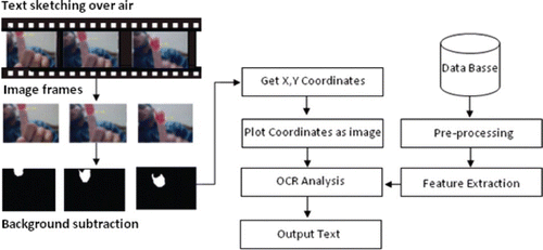
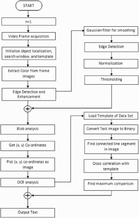
The real-time video-based pointing method proposed herein consists of the following steps. It tracks the motion of the colored fingertip, finds its coordinates, and plots such coordinates. After plotting the coordinates, OCR is applied on the plotted image, the output is matched with the trained database for OCR, and the most possible match is achieved and displayed, as shown in .
3.1 Object localization
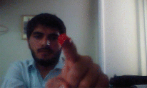
The image extracted from the video sequence is shown in . After the extraction, the object is localized as follows:
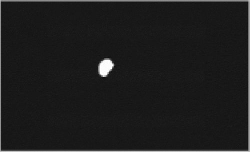
Extract color image from reference. The proposed method basically tracks the motion of the index finger, which is colored red. There is no reference image, and every previous image is the reference to the next image. Then the difference of the images is taken, and the color and object movement are extracted. shows the background-abstracted image.
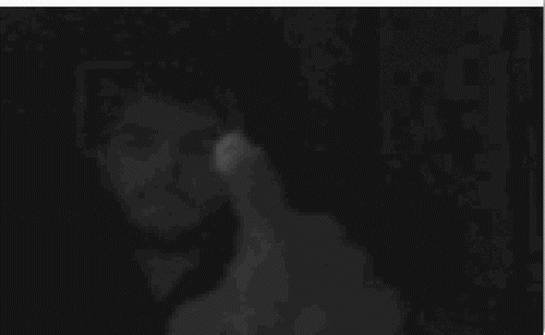
Edge enhancement (EE). The edge enhancement technique makes the object localization algorithm robust to noise, varying lighting conditions, obscuration, and object fading, even in low-contrast imagery. shows an edge-enhanced image. The edge enhancement process consists of the following four operations:
3.2 Gaussian smoothing
It is a well-known fact that the video frames captured from any camera have noise in them at least to some extent, especially when the ambient light around the sensor is low [Citation15–17]. If the frames are extracted from a compressed video clip instead of from a camera, they usually contain undesired artifacts in addition to noise [Citation18,Citation19]. The smoothing process attenuates the sensor noise and reduces the effects of the artifacts, resulting in lesser false edges in the subsequent operation (i.e. edge detection). The average and box filters can be used to attenuate the noise and artifacts in images, but they introduce unwanted blur, resulting in the loss of the fine details of the object. On the contrary, the Gaussian smoothing filter performs the same task without sacrificing the fine details of the object. Thus, w×w Gaussian smoothing filters with standard deviation is applied on the search window and the template, as shown in the following equation [Citation20]:
3.3 Edge detection
Edge-enhanced gray-level images were used instead of actual gray-level images because edge images are less sensitive to lighting conditions. The standard horizontal and vertical Sobel masks were applied on the smoothed image, and the two resulting images of the horizontal and vertical derivative approximation (Eh and Ev) were obtained, followed by the gradient magnitude image (E). This image is normally obtained as in the following equation [Citation21]:
3.4 Normalization
It was found in the experiments that the dynamic range of the edge image E is often too narrow towards the darker side compared with the available pixel value range [0, 255], especially in low-contrast imagery. Conventionally, the edge image is converted to a binary image using a predefined threshold, but this approach does not work well in a template-matching application because the rich content of the gray-level edge features of the object is lost in the process of binarization. The edges are enhanced using a normalization procedure given by
3.5 Thresholding
To remain on the safe side and to quench the false edges due to the smoothed noise and artifacts, a thresholding operation is performed, as follows:
where Ent is the normalized and threshold edge image. It may be noted that Ent is not a binary image but an edge-enhanced gray-level image adequately containing the important features of the object.
3.5.1 Blob analysis
In blob analysis, the image properties are extracted after edge enhancement and extraction of the color region. As blob analysis cannot be directly applied on binary images for feature extraction, for such purpose in this study, the image was first labeled. The labeling procedure is used to find the connected points in binary images, which are further utilized for blob analysis. represents the labeled image with the connected points.
In blob analysis, the set of properties is measured from the labeled image. The positive-integer elements of the labeled image correspond to different regions. For example, the set of labeled elements equal to 1 corresponds to region 1, that equal to 2 corresponds to region 2, and so on. The set of properties (i.e. area, bounding box, centroid, and orientation) are returned in an array.
3.5.2 Plotting of (X,Y) coordinates
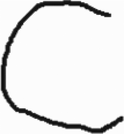
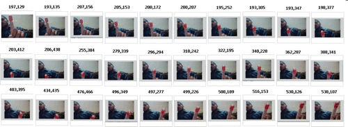
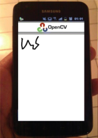
After extracting the properties of the object from the still video frame, the object is tracked throughout the video frame, and its (X, Y) coordinates are obtained, as shown in . After the extraction of the (X, Y) coordinates, these coordinates are represented in the form of an image, which is further taken into consideration. Here, the mirror images are obtained by simply shuffling the X coordinates rather than inverting the image, while the Y coordinates remain the same. shows the plotted image.
3.6 OCR analysis
OCR is a designed image-processing tool used to read and recognize characters by reading an image. The purpose of using OCR is to read the resultant character after tracking the object. The OCR in this work is defined as follows:
Loading the template. A template is basically a data set used to compare the resultant images and to find their relation with a text. The data set basically contains the test images that can be drawn while drawing text in the air.
Converting the test image to binary form. To process an image, it is necessary to convert an image to its binary form because a binary image contains 0 or 1pixel values, which are easy to deal with. After the labeling, the labeled images correspond to different regions. The set of labeled elements equal to 1 corresponds to region 1, that equal to 2 corresponds to region 2, and so on.
Finding the connected line segment and correlation. The purpose of finding the connected line segment is to read the shape of the resultant image. presents a resultant image. This is done by reading the labeled image linewise and storing the result in an array. The test image shown below shows the working of the connected line segment.
Proposed algorithm. shows the flowchart of the proposed algorithm. In the proposed algorithm, the video is first acquired, the color is extracted from the video frame images, edge detection and enhancement are carried out to detect the object, blob analysis is performed to bound the object, and its X, Y coordinates are sought in the video frames images. After this, these coordinates are plotted, OCR analysis is performed, and the output is taken.
4. Results and discussion
4.1 “W” results
For the experiment, the Samsung Galaxy3 mobile phone with the Android 4.0 (Ice Cream Sandwich) operating system was used. Its 1.9-megapixel frontal camera with a frame rate of 30 fps was used. The proposed method was applied for both indoor and outdoor locations, and it was found to work well in both.
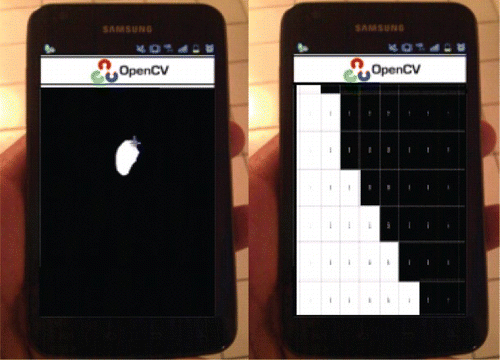
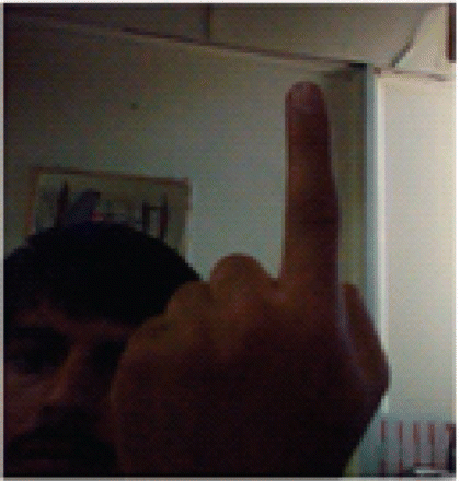
The proposed method tracks the colored fingertip in a video file by capturing the video from any video-capturing device. Then it reads the video file and processes the video framewise by reading the images. After reading the framewise images from the video file, the designed algorithm extracts the red color from the frames, as shown in .
EE is then carried out to detect the edge of the colored fingertip. The enhanced edge is shown in .
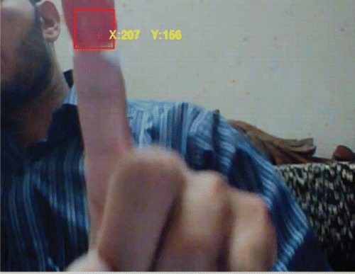
After edge enhancement, the designed system extracts the (X, Y) coordinates of the colored image by applying the bounding box on the extracted image. The bounding box on the colored image is shown in .
After the extraction of the (X, Y) coordinates, these values are stored in an array and are displayed in an image form, as in .
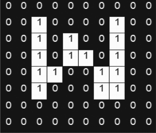
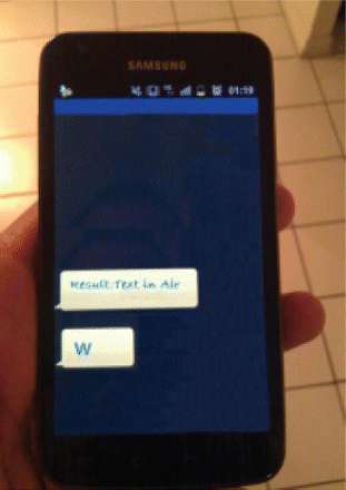
This image is then given to the OCR module for recognition. It first loads the training test templates. The training set for word “W” is shown in . After loading the complete template for alphanumeric characters, it is compared with the resultant image to find the maximum similarity, and the result is displayed in a text file showing the resultant character, as shown in .
Figure 16. Training images.
4.2 “Hello world”results
As mentioned above, the proposed method works on the color segment of the frame and tracks the entire region for it. Two characters could be differentiated by two means.
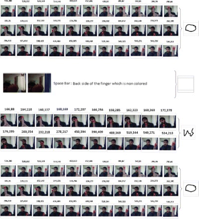
Use tape only for the frontal portion of the index finger, and after writing each character, just twist the finger (where there is no tape) and then write the next word. When the proposed method does not find a colored object, it is assumed that one character has been completed.
Another way is to add waiting time after writing each character. The waiting time should be some milliseconds, which will yield duplicate frames with the same features. As discussed above, the previous frame is used as a reference image, and the difference between the two images is taken. A small difference (in most cases, near zero) in the case of the duplicate frame (X, Y coordinates), means that one character has been completed. Both cases are clearly shown in .
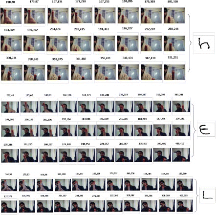
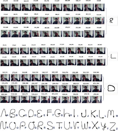
The developed system was trained on the following images shown in .
Furthermore, the proposed method was tested for different shaped characters, which numbered more than 3000. The average accuracy rate of the proposed method was 92.083%. shows the accuracy of the proposed algorithm for each letter. The proposed algorithm shows the least accuracy rate (81%) for the letters D and V.
Table 1. Accuracy rate for each letter.
The reason behind such a least accuracy rate is that while writing in the air, the letter D is sometimes captured in such a way that it looks similar to the letter O because the writer could not see the trajectories, making the letter loci very bad. A similar case is true with the letter V, which is sometimes captured as the letter U or W. Finally, the reorganization speed of the proposed system was calculated. presents the results of the recognition of different characters after obtaining the (X, Y) coordinates. The results show that the proposed system is faster than the existing method, as presented in [Citation7],where it was shown that for the word “new”, the recognition method proposed in such paper requires 1.02 s while the method proposed in the present paper requires only 0.663678 s. Another solution for finger tracking without color-based tracking is skin-based tracking [Citation22].Skin-based detection mainly depends on the stereo image, background subtraction, skin segmentation, region extraction, and feature extraction. shows the results of both the color- and skin-based finger detection methods. As the complex-computation skin-based detection method is slower than the proposed system, which requires only a single camera followed by color segmentation, it can track only the colored finger and applies OCR on it.
Table 2. Time required for recognition.
5. Conclusion
This paper presents a video-based pointing method that allows the writing of English text in the air using a mobile camera. The proposed method involves two main tasks: tracking the colored fingertip in the video frames and then applying English OCR on the plotted images to recognize the written characters. Moreover, the proposed method provides a natural human–system interaction that does not require a keypad, pen, glove, or any other device for character input. It requires only a mobile camera and red color for reorganizing the fingertip. For the experiment, an application was developed using OpenCv with the JAVA language. The proposed method showed an average accuracy rate of 92.083% in character recognition. The overall writing delay shown by the proposed method was 50 ms per character. The proposed method is also applicable to all disconnected languages. It has one serious issue, though: it is color-sensitive in that the existence of any red-colored object in the background before the start of and during the analysis can lead to false results.
References
- A. Yilmaz, O. Javed, M. Shah, ACM Comput Surv. 38, 1 (2006).
- Y-H. Chang, C-M. Chang in User Interfaces, edited by Rita Matrai (INTECH, Zagreb, 2010).
- E.B. Sudderth, M.I. Mandel, W.T. Freeman, and A.S. Willsky, Mit Laboratory For Information & Decision Systems Technical Report P-2603, presented at IEEE CVPR Workshop On Generative Model Based Vision, pp. 1–9 (2004).
- R. Y. Wang and J. Popovic, Real-Time Hand-Tracking with a Color Glove, ACM Transaction on Graphics (SIGGRAPH 2009), 28(3), August 2009.
- J. Hannuksela, S. Huttunen, P. Sangi, J. Heikkila, in Proceedings of the 4th European Conference on Visual Media Production, pp. 1–6, London, UK, 2007.
- T. Asano, S. Honda, presented at 19th IEEE International Symposium on Robot and Human Interactive Communication Principe di Piemonte – Viareggio, Italy, pp. 56–61, September 12–15, 2010.
- S. Vikram, L. Li, S. Russell, CHI 2013 Extended Abstracts, April 27–May 2, 2013, Paris, France.
- T.A.C. Bragatto, G.I.S. Ruas, and M.V. Lamar,presented at the IEEE ITS, pp. 393–397 (2006).
- H.M. Cooper, Ph.D. thesis, Centre for Vision, Speech and Signal Processing Faculty of Engineering and Physical Sciences, University of Surrey, UK, 2012.
- Y. Araga, M. Shirabayashi, K. Kaida, and H. Hikawa, presented at the IEEE World Congress on Computational Intelligence, Brisbane, Australia, 2012.
- R Yang and Sudeep Sarkar, Computer Vision and Image Understanding, 113 (6), 663-681 (2009).
- L. Neumann and J. Matas, ACCV 2010, Part III, LNCS 6494, (Springer, Berlin, 2011), pp. 770–783.
- C. Yao, X. Zhang, X. Bai, W. Liu, Y. Ma, and Z. Tu, PLos One J. 8(8) (2013).
- R. Wang, S. Paris, and J. Popovi'c, presented at the Eurographics/ACM SIGGRAPH Symposium on Computer Animation, UBC Campus, Vancouver 2011.
- M.J. Buckingham, B.V. Berknout, and S.A.L. Glegg, Imaging the ocean with ambient noise. Nature 356 (6367), 327 (1992).
- S.V. Vaseghi, Advanced Digital Signal Processing and Noise Reduction, 4th ed. (Wiley, New York, 2008).
- K.N. Platanioti and A.N. Venetsanopoulos, Color Image Processing and Applications (Springer, Toronto, 2000).
- S.D. Kim, J. Yi, H.M. Kim, and J.B. Ra, IEEE Trans Circuits Syst. Video Technol. 9(1), 156 (1999). doi: 10.1109/76.744282
- B. Zeng, Signal Process. 79(2), 205–211 (1999). doi: 10.1016/S0165-1684(99)00094-8
- J. Weickert, Anisotropic Diffusion in Image Processing, 1 (Teubner, Stuttgart, 1998).
- http://homepage.cs.uiowa.edu/~cwyman/classes/spring08-22C251/homework/sobel.pdf.
- http://www.cs.utoronto.ca/~smalik/downloads/2503_project_report.pdf.
