
Abstract
In this work, a systematic approach to controlling the orientation of a liquid-crystalline simple cubic blue phase (BPII) was carried out using a conventional surface rubbing treatment method. A more uniform lattice plane alignment in BPII was produced than in the liquid-crystalline-body-centered blue phase (BPI) using rubbed polyimide (PI) films on glass substrates. A single-color monodomain-like BPII was achieved regardless of the rubbed PI substrate pretilt angle. Additionally, single-color monodomain-like BPIIs with three elementary colors (red, green, and blue) were prepared, simply by changing the percentage of the chiral dopant.
Introduction
Liquid-crystalline phases possessing chirality display a self-assembled periodic structure, consequently giving rise to photonic band structures for visible light [Citation1]. Among these liquid-crystalline phases, cubic blue phases (BPs) have a cubic symmetry with a unique three-dimensional structure consisting of double-twist cylinders and disclinations [Citation2]. There are two cubic BP classifications: a body-centered-cubic BP (BPI) and a simple cubic BP (BPII), numbered in the order of increasing temperature between the chiral nematic (N*) and isotropic phases [Citation3–5]. These cubic BPs have attracted attention in the photonics field due to their aforementioned spontaneous periodic structures [Citation6,Citation7].
Typically, cubic BPs exhibit a polycrystalline structure with small platelet domains when placed between two glass substrates free from special treatment. In this study, the relative Bragg reflection intensities resulting from their periodic structures were determined by the lattice plane orientation distributions of different platelet domains, which varied from sample to sample [Citation8]. Nevertheless, a high and constant reflection intensity originating from a specific plane of the cubic BP structure is desirable for obtaining high-performance photonic devices such as a mirrorless liquid-crystalline BP laser [Citation9]. Thus, the preparation of a uniform, single-color monodomain BP is indispensable from an application viewpoint. Although several works on monodomain BP have been reported [Citation10,Citation11], it is widely known that controlling the BP orientation is considerably difficult because the director is not uniform, unlike that of nematic liquid crystals [Citation12]. Until now, however, the previously described orientation control difficulty has been primarily demonstrated using cubic BPI, as the cubic BPII is stable only in an extremely narrow temperature range (typically 0–1°C) [Citation5]. Consequently, detailed and systematic approaches to the orientation control of BPII have been obstructed.
In this work, a systematic attempt was made to obtain a uniform lattice plane alignment in BPII with a relatively wide temperature range (∼4°C), using a conventional rubbing treatment method on glass substrates covered with commercially available polyimides (PIs). Interestingly, the BPII tended to easily achieve a relatively uniform alignment than the BPI via the rubbing treatment. Therefore, a monodomain-like, single-color BPII was successfully prepared using a conventional surface rubbing treatment method. It is anticipated that the single-color monodomain-like BPII would find applications in high-performance photonic crystal devices such as low-threshold BP lasers [Citation13,Citation14].
Experiment
Materials
To obtain the cubic BP, a host nematic (N) mixture consisting of a rod-like nematogen (80 wt%) and a bent-core molecule A (BC-A, 20 wt%) was prepared. In general, mixing bent-core molecules tends to expand the temperature range of cubic BP [Citation15,Citation16]. The rod-like nematogen (MLC-7026-000, Merck Co.) that was used in this study is a commercially available multicomponent mixture with a negative dielectric anisotropy (Δε = −3.7 at 25°C, 1.0 kHz). The N-phase-based BC-A (synthesized by the authors) presented the following phase sequence with decreasing temperature: Iso-(99°C)-N-(82°C)-B4-(76°C)-Cryst [Citation17]. A host N* mixture was prepared by blending the chiral dopant (ISO–(6OBA)2) with the host N mixture [Citation18]. The chemical structures of the BC-A and chiral dopant that were used in this work are shown in .
Figure 1. Chemical structures of (a) BC-A and (b) the chiral dopant used in this work.
Cell fabrication
The cells that underwent rubbing treatment were fabricated in the following steps. First, commercially available PIs were spin-coated on slides, which were then cured at 180°C for 20 min. Four completely different types of homogeneous PI materials were used: (1) a commercial PI (Nissan Chem.) with an unknown pretilt angle (PI-1); (2) a commercial PI (SE-2414, Nissan Chem.) with a 1–2° pretilt angle (PI-2); (3) a commercial PI (AL22620, JSR) with a 3–4° pretilt angle (PI-3); and (4) a commercial PI (SE-7492K, Nissan Chem.) with a 4–5° pretilt angle (PI-4). Next, rubbing was performed with a commercial rubbing machine (RM-50, EHC Co., Ltd.) and a cotton velvet cloth (#8007-090, Agehara Textile Ind. Co., Ltd.). Subsequently, two slides were assembled, ensuring an anti-parallel rubbing direction between them. The prepared chiral mixtures were then injected as an isotropic phase into the arranged sandwiched cells.
Results and discussion
BP in the rubbing-treated cells
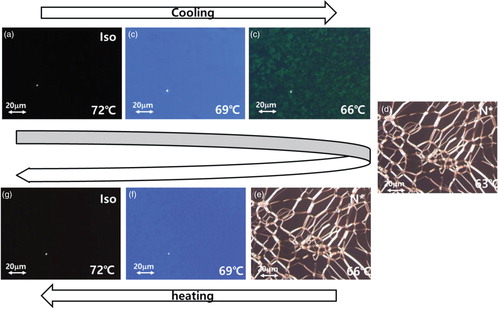
illustrates a typical polarized optical microscopy (POM) image sequence, revealing the textures of a chiral mixture (LC-1) composed of the host N* mixture blended with a 7 wt% chiral dopant. For the POM observations, the LC-1 was injected into ∼10-µm-thick cells coated with PI-1 (Cell-1), which had been rubbed on glass slides. Upon cooling at a 0.1°C min−1 rate, the isotropic liquid ((a)) changed to a uniform fluid phase with a blue color, shown in (b), which did not appear to comprise the multi-domain platelets usually observed in cubic BP. Upon further cooling, the uniform fluid phase progressed to a phase possessing the small platelets that are usually observed in cubic BP ((c)), followed by an N* phase with oily streaks ((d)). For the reverse, upon heating at a 0.1°C min−1 rate, the N* phase continued as shown in (e), after which it progressed to the uniform color phase upon further heating ((f)). Finally, the uniform phase changed back to the isotropic liquid phase ((g)).
Figure 2. Typical POM images revealing the textures of LC-1 in Cell-1: (a) isotropic liquid at 72°C; (b) the higher-temperature-range phase with a uniform blue color at 69°C; (c) the lower-temperature-range phase at 66°C; and (d) the N* phase at 63°C during the cooling process. (e) The N* phase at 66°C; (f) the uniform blue color phase at 69°C; and (g) the isotropic liquid phase at 72°C during the heating process.
To precisely determine the temperatures marking the boundaries of the higher- and lower-temperature-range phases between the isotropic liquid and the N* phase upon cooling, the temperature dependence of the Bragg reflection from LC-1 was examined. Reflectance spectra were acquired using a microscope spectrometer set up by the authors. The light beam was focused on the sample surface at normal incidence, and the light reflected from the sample cell was collected using a multichannel spectrometer. The measurement spot was about 1.5 mm in diameter. The typical size of a platelet in BP observed in non-rubbing-treated cells ranges from several micrometers to several tens of micrometers. Several reflectance spectra were observed at different places within the cell. (a) displays the typical reflectance profiles of the higher- and lower-temperature-range phases. The higher-temperature-range phase exhibited a single peak with a sharp and high reflectance profile due to its relatively uniform alignment. In comparison, the lower-temperature-range phase showed two peaks with relatively low reflectance profiles originating from the multi-lattice plane orientations of the different platelet domains.
Figure 3. (a) Typical reflectance profiles of the higher-temperature-range phase (blue circles) and the lower-temperature-range phase (red circles). Temperature dependence of the LC-1 Bragg reflection wavelength during the (b) cooling and (c) heating processes.
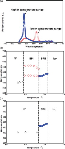
(b) shows the Bragg reflection wavelength temperature dependence of the aforementioned LC-1, with the peak wavelength collected relative to the temperature during cooling (0.1°C min−1). As shown in (b), a distinct difference was observed in the temperature dependence of the Bragg reflection wavelength between the higher- and lower-temperature-range phases during cooling. In the higher-temperature-range phase, the Bragg reflection wavelength shifted toward slightly shorter wavelengths with decreasing temperature, explained as the result of the higher-temperature-range phase being the BPII [Citation5,Citation8,Citation19]. In contrast, for the lower-temperature-range phase, the Bragg reflection wavelength shifted to slightly longer wavelengths with decreasing temperature, which is related to BPI [Citation5,Citation8,Citation19]. Furthermore, the temperature dependence of the Bragg reflection wavelength during heating (0.1°C min−1) was also investigated, as shown in (c). The BPI, which appeared at a lower temperature range upon cooling, was not observed upon heating. The thermodynamic equilibrium phase transition points are better reflected during the heating process rather than during cooling, as supercooling readily occurs with the latter [Citation20]. At temperatures >68°C, the Bragg reflection wavelength gradually increased with the temperature. This trend corresponds with that observed for BPII, which appeared at a higher temperature range upon cooling. Based on the POM results and Bragg reflection observations, it was confirmed that the temperature range of both a thermodynamically stable and a single-color monodomain BPII was about 4°C during the heating process in this work, which is much wider than that of the conventional BPII. The temperature range of the BPII in this work, however, is still narrow and limits the practical application. To expand the temperature range of BPII, polymer-stabilized BPII was challenged [Citation13]. In this work, a negative liquid crystal was employed, but monodomain-like BPII can also be obtained in positive liquid crystal systems according to the investigations made in this work.
Dependence on the PI material with different pretilt angles
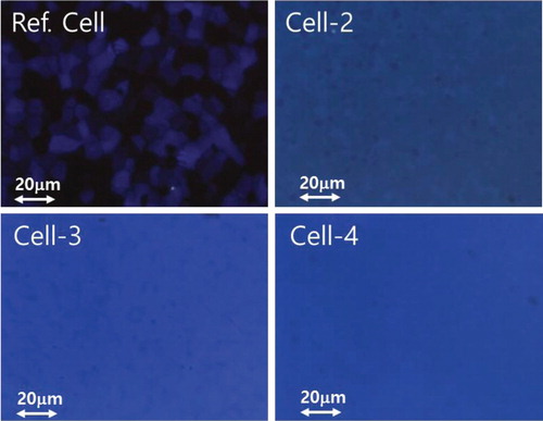
Next, three different types of sandwiched cells with varied homogeneous PI materials and 10 µm cell gaps were fabricated: (1) a pair of slides with PI-2 (Cell-2); (2) a pair of slides with PI-3 (Cell-3); and (3) a pair of slides with PI-4 (Cell-4). LC-1 was injected into the three different cells, respectively, and BPII was also observed during the heating process. shows the POM images of BPII at 69°C (1°C above TBPII, the transition temperature from the N* phase to BPII during heating) for the three different cells. As a reference, the texture of the LC-1 prepared in a cell without surface-treated slides is also illustrated. The cubic BP consists of multi-platelets usually observed in cubic BPII, and in this work, they were observed in the reference cell. In contrast, a monodomain-like BPII, revealing a single color (similar to that shown in (f)), was attained in all the three cells, irrespective of the PI pretilt angles that were used, as shown in . Although some areas with a non-uniform domain were also observed in the cell, an entirely uniform BP domain that grew to a size of over 500 μm could be realized. The non-uniform area could also be improved through repeated cooling and heating cycles at a rate of 0.1 °C/min over the BP temperature ranges [Citation13]. In general, rubbing treatments have a minimal influence on the alignment of the BPI. In this study, however, the rubbing treatment easily created a single-color monodomain-like BPII. It is concluded that this can be attributed to the difference in cubic structure between BPI and BPII.
Figure 4. POM images of BPII at 69°C in the reference cell (top) and the three different cells with varying PI tilt angles, from left to right: 1–2° pretilt angle (Cell-2), 4–5° pretilt angle (Cell-3), and 5–6° pretilt angle (Cell-4).
BPII with different amounts of chiral dopant
Finally, two other types of chiral mixtures were prepared in addition to the previously described LC-1. LC-2 and LC-3 were chiral mixtures blended with 6.5 and 6.2 wt% chiral dopant, respectively. The prepared chiral mixtures (LC-1, LC-2, and LC-3) were all injected into the aforementioned Cell-2 structure.
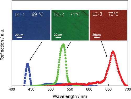
displays the typical reflection profiles of the three different chiral mixtures in the rubbing-treated cells at an identical reduced temperature (1°C above TBPII). The inset of also shows the POM images of the three different chiral mixtures. As shown in this inset, a single-color monodomain-like BPII with a high reflection can be realized irrespective of the prepared chiral mixture used. The sharp reflections originated from a lattice plane of the cubic BPII. As a result, single-color monodomain-like BPIIs were successfully prepared based on the three elementary colors (red, green, and blue), simply by optimizing the amount of the chiral dopant.
Figure 5. Typical reflection profiles of the three different chiral mixtures LC-1, LC-2, and LC-3 at an identical reduced temperature (1°C above TBPII), giving blue, green, and red reflections, respectively.
Conclusions
In this work, the alignment for BPII was examined systematically and in detail. It was confirmed that the lattice plane of cubic BPII can be easily controlled through the rubbing treatment of PI on glass substrates. In general, rubbing treatments had a minimal influence on the alignment of the body-centered-cubic BP (BPI), according to a previous study [Citation12]. In this study, however, the rubbing treatment easily created a single-color monodomain-like simple cubic BP (BPII) with uniformly aligned periodic lattice planes. This stems from the fact that BPII possesses a simple cubic structure while BPI possesses a body-centered-cubic structure. These monodomain-like cubic BPII materials are promising as photonic-device applications such as mirrorless laser media.
Funding
This work was supported by the Basic Science Research Program (NRF-2013R1A1A2061996) through the National Research Foundation of Korea (NRF).
Additional information
Kibeom Kim obtained his B.S. in Information & Electronics degree from the Department of Advanced Materials Engineering of Kyung Hee University in 2014, and he is currently an M.S. candidate in the same institute. He has been working on optic materials, specifically unconventional liquid-crystalline materials.
Sunhwan Kim obtained his B.S. and M.S. in Information & Electronics degrees from the Department of Advanced Materials Engineering of Kyung Hee University in 2012 and 2014, respectively. After graduating, he joined SKC as a research engineer in 2015.
Seong-Yong Jo obtained his B.S. in Information & Electronics degree from the Department of Advanced Materials Engineering of Kyung Hee University in 2015, and he is currently an M.S. candidate in the same institute. He has been working on photonic materials and devices using a self-assembled liquid crystallinity.
Suk-Won Choi is an associate professor at the Department of Advanced Materials Engineering for Information & Electronics of Kyung Hee University. He obtained his B.S. degree from Hanyang University in Seoul, South Korea, and his M.S. and Ph.D. degrees from Tokyo Institute of Technology in Tokyo, Japan. Since joining the faculty of Kyung Hee University in 2008, he has been working on organic soft materials for optic and photonic applications. He is especially interested in liquid-crystalline materials for optic and photonic devices.
References
- S.T. Hur, B.R. Lee, M.J. Gim, K.W. Park, M.H. Song, and S.W. Choi, Adv. Mater. 25, 3002–3006 (2013). doi: 10.1002/adma.201204591
- H. Kikuchi, Struct. Bond. 128, 99–117 (2008). doi: 10.1007/430_2007_075
- M.J. Gim, S.T. Hur, K.W. Park, M. Lee, S.W. Choi, and H. Takezoe, Chem. Commun. 48, 9968–9970 (2012). doi: 10.1039/c2cc34114j
- M.J. Gim, K.Y. Park, and S.W. Choi, Opt. Mater. 36, 414–418 (2013). doi: 10.1016/j.optmat.2013.10.002
- K.W. Park, M.J. Gim, S. Kim, S.T. Hur, and S.W. Choi, ACS Appl. Mater. Interfaces. 5, 8025–8029 (2013). doi: 10.1021/am403109q
- H.J. Coles, and S.M. Morris, Nat. Photon. 4, 676–685 (2010). doi: 10.1038/nphoton.2010.184
- S. Yokoyama, S. Mashiko, H. Kikuchi, K. Uchida, and T. Nagamura, Adv. Mater. 18, 48–51 (2006). doi: 10.1002/adma.200501355
- E.I. Demikhov, V.K. Dolganov, and S.P. Krylova, Sov. Phys. JETP. 66, 998–1001 (1987).
- S. Kim, K. Kim, S.Y. Jo, and S.W. Choi, Mol. Cryst. Liq. Cryst. 611, 186 (2015).
- J. Yan, S.T. Wu, K. Cheng, and J.W. Shiu, Appl. Phys. Lett. 102, 081102 (2013). doi: 10.1063/1.4793750
- P. Nayek, H. Jeong, H.R. Park, S.W. Kang, S.H. Lee, H.S. Park, H.J. Lee, and H.S. Kim, Appl. Phys. Express. 5, 051701 (2012). doi: 10.1143/APEX.5.051701
- S.I. Yamamoto, Y. Haseba, H. Higuchi, Y. Okumura, and H. Kikuchi, Liq. Cryst. 40, 639–645 (2013). doi: 10.1080/02678292.2013.772664
- K. Kim, S.T. Hur, S. Kim, S.Y. Jo, B.R. Lee, M.H. Song, and S.W. Choi, J. Mater. Chem. C. 3, 5383–5388 (2015). doi: 10.1039/C5TC00420A
- B.A. San Jose, J.L. Yan, and K. Akagi, Angew. Chem. Int. Ed. 53, 10641–10644 (2014). doi: 10.1002/anie.201404250
- M. Lee, S.T. Hur, H. Higuchi, K. Song, S.W. Choi, and H. Kikuchi, J. Mater. Chem. 20, 5813–5816 (2010). doi: 10.1039/c0jm01087a
- S.T. Hur, M.J. Gim, H.J. Yoo, S.W. Choi, and H. Takezoe, Soft Matter. 7, 8800–8803 (2011). doi: 10.1039/c1sm06046e
- T. Niori, J. Yamamoto, and H. Yokoyama, Mol. Cryst. Liq. Cryst. 409, 475–482 (2004). doi: 10.1080/15421400490434072
- T. Iwata, K. Suzuki, H. Higuchi, and H. Kikuchi, Liq. Cryst. 36, 947–951 (2009). doi: 10.1080/02678290903165482
- H.J. Coles, and M.N. Pivnenko, Nature. 436, 997–1000 (2005). doi: 10.1038/nature03932
- S. Shibayama, H. Higuchi, Y. Okumura, and H. Kikuchi, Adv. Funct. Mater. 23, 2387–2396 (2013). doi: 10.1002/adfm.201202497