
Abstract
The efficiency loss process of hyper-fluorescent organic light-emitting diodes (OLEDs) was analyzed with different fluorescent emitters. Two blocking units of tert-butyl and 2-phenylpropan-2-yl in fluorescent emitters suppressed the Dexter energy transfer from the host and thermally activated delayed fluorescent (TADF) sensitizer to the fluorescent emitter and concentration quenching caused by intermolecular interaction. The performance of the green hyper-fluorescent OLEDs showed that the device of the fluorescent emitter with the 2-phenylpropan-2-yl unit achieved a high external quantum efficiency of 18.1% with a low efficiency roll-off, compared to the device of the fluorescent emitter with the tert-butyl unit. This study demonstrated the usefulness of the 2-phenylpropan-2-yl blocking unit of the fluorescent emitter for hyper-fluorescent OLEDs, and exhibited the directionality of the development of hyper-fluorescent OLEDs.
1. Introduction
Fluorescent organic light-emitting diodes (OLEDs) have been used for several decades because of their good stability [Citation1–3]. However, they have limited internal quantum efficiency because only singlet excitons can be used for light emission [Citation4]. To overcome such limitation by utilizing all generated excitons, thermally activated delayed fluorescence (TADF) emitters emerged to harvest the triplet excitons using the small singlet–triplet energy gap [Citation5–8]. The small energy gap between the singlet state and the triplet state in the TADF materials can induce reverse intersystem crossing from the triplet state to the singlet state. Therefore, the TADF materials can achieve 100% internal quantum efficiency. Although the TADF materials have the merit of quantum efficiency, they do not have good color purity and good emission ability due to the torsion between their donor and their acceptor [Citation9].
These issues of TADF emitters can be resolved by the device strategy of hyper-fluorescence, which uses TADF materials as sensitizers and fluorescence materials as emitters. Ideally, the triplet exciton harvesting by the TADF sensitizer, and the Förster energy transfer from the TADF sensitizer to the fluorescent emitter, can achieve 100% internal quantum efficiency in hyper-fluorescent OLEDs, with good color purity and good emission stability of the fluorescent emitter [Citation10,Citation11]. However, it is difficult to prevent Dexter energy transfer from the host and TADF sensitizer to the fluorescent emitter and concentration quenching caused by intermolecular interaction [Citation12–14].
Herein, we developed hyper-fluorescent OLEDs with 2,6-di-tert-butyl-N9,N9,N10,N10-tetrakis(4-(tert-butyl)phenyl)anthracene-9,10-diamine (6tBPA), N9,N9,N10,N10-tetrakis(4-(2-phenylpropan-2-yl)phenyl)anthracene-9,10-diamine (PhtBuPAD) as two different fluorescent emitters and 9’-(4-(4,6-diphenyl-1,3,5-triazin-2-yl)dibenzo[b,d]furan-3-yl)−9,9’’-diphenyl-9H, 9’H,9’’H-3,3’:6’,3-tercarbazole (TCzTrzDBF) as the TADF sensitizer [Citation15,Citation16]. It was demonstrated that the suppression of the Dexter energy transfer and the concentration quenching by the 2-phenylpropan-2-yl unit in the fluorescent emitter enabled a high maximum external quantum efficiency (EQE) of 18.1% with a low efficiency roll-off.
2. Results and discussion
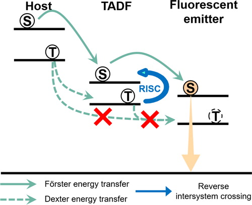
The hyper-fluorescent emission process is shown in Figure . The TADF sensitizer harvests triplet excitons by reverse intersystem crossing (RISC). In addition, the Förster energy transfer from the TADF sensitizer to the fluorescent emitter enables utilization of 100% excitons for emission from the singlet state in the fluorescent emitter. At this time, the prevention of Dexter energy transfer from the host and TADF sensitizer to the fluorescent emitter is important to maximize the performance of hyper-fluorescent OLEDs because all the triplet excitons in the fluorescent emitter are lost through a non-radiative process. To prevent Dexter energy transfer, two fluorescent emitters with blocking units were adopted. The first emitter was 6tBPA, which has a tert-butyl unit as a blocking unit, and the second emitter was PhtBuPAD, which has a 2-phenylpropan-2-yl unit as the blocking unit.
Figure 1. The emission mechanism of hyper-fluorescent OLEDs.
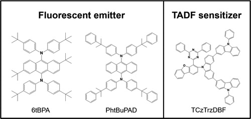
In addition, TCzTrzDBF was used as the TADF sensitizer for several reasons. First, the rigidity and steric effect of the dibenzofuran unit, the 3 and 4 positions of which were substituted with a donor and acceptor, can induce large distortion with good stability. This ortho-substitution would cause a small singlet–triplet energy gap and a short delayed fluorescent lifetime [Citation17]. Second, the TCzTrzDBF sensitizer can suppress Dexter energy transfer from the TADF sensitizer to the fluorescent emitter because the tercarbazole donor was orthogonal to the core structure. Finally, the emission spectrum of the TCzTrzDBF sensitizer overlapped with the absorption spectrum of the 6tBPA and PhtBuPAD emitters. This is an important factor of Förster energy transfer from the TADF sensitizer to the fluorescent emitters. The molecular structure of the two fluorescent emitters and the TADF sensitizer is shown in Figure .
Figure 2. Molecular structure of fluorescent emitters and sensitizer.
Before device development, the photophysical properties of the TADF sensitizer and the fluorescent emitters were analyzed. The UV-Vis absorption spectra of the fluorescent emitters in tetrahydrofuran (THF) solutions were measured. The solution concentration was 1.0×10⁻⁵ M. The photoluminescence (PL) spectra of the TADF sensitizer and the fluorescent emitters in THF solutions were also measured. There was an overlap between the absorption spectra of the two fluorescent emitters and the emission spectra of the TADF sensitizer. This verified the Förster energy transfer from the TADF sensitizer to the fluorescent emitters. These spectra are shown in Figure (a).
Figure 3. (a) The absorption spectra and emission spectra of the fluorescent emitters and TADF sensitizer in THF solutions, and (b) The emission spectra of the fluorescent emitters and TADF sensitizer doped films with DPEPO host.
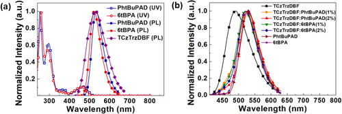
To identify the energy transfer from the TADF sensitizer to the fluorescent emitters, the PL spectra of the TADF sensitizer and fluorescent emitters doped films with a Bis[2-(diphenylphosphino)phenyl]ether oxide (DPEPO) host were also investigated, as shown in Figure (b). The doping concentration of TCzTrzDBF was 20% in the DPEPO host, and that of the PhtBuPAD and 6tBPA was 1% in the DPEPO host. The doping concentration of the co-doped TCzTrzDBF: PhtBuPAD or 6tBPA films was 20%: 1% or 2%. The maximum wavelength of the TCzTrzDBF doped film was 491 nm, which was blue-shifted by 40 nm compared to the wavelength of TCzTrzDBF in the THF solution due to the solvatochromic effect. The PL spectra of the PhtBuPAD and 6tBPA emitters doped film had the same tendency as those in the THF solution. The spectra of the TCzTrzDBF and PhtBuPAD co-doped films had the maximum wavelength of 525 nm at the 1% doping concentration, and 529 nm at a 2% doping concentration, which agreed with the peak wavelength of the PhtBuPAD doped film, indicating complete energy transfer at the 2% doping concentration. The spectra of the TCzTrzDBF and 6tBPA co-doped films had the maximum wavelength of 521 nm at the 1% doping concentration, and 523 nm at the 2% doping concentration. Considering that the 6tBPA doped film had the maximum wavelength of 523 nm, there was also complete energy transfer at the 2% doping concentration. The PL spectra of the films verified the energy transfer from the TADF sensitizer to the two fluorescent emitters. The photophysical properties of the TADF sensitizer and the fluorescent emitters are shown in Table .
Table 1. The photophysical properties of the TADF sensitizer and the fluorescent emitters.
The photophysical transition of the films was further investigated using transient PL analysis, as shown in Figure . The decay of the films means the disappearance of the excitons in the films according to time. The delayed fluorescence of the TADF sensitizer doped film was from the intersystem crossing and reverse intersystem crossing process. The delayed fluorescent lifetime of the TCzTrzDBF sensitizer doped film was 4.38 µs. The fluorescence lifetimes of the PhtBuPAD and 6tBPA were 22.5 and 18.6 ns, respectively, without any delayed fluorescence. In the case of the co-doped film, there was an extra pathway of Förster energy transfer from the TADF sensitizer to the fluorescent emitters, which can accelerate the decay of the films. If the doping concentration of the fluorescent emitters is high, the possibility of energy transfer from the TADF sensitizer to the fluorescent emitters will be high as well. Thus, the decay of the films with the 2% doped fluorescent emitter was accelerated compared to that of the films with the 1% doped fluorescent emitter. The delayed fluorescent lifetime of the TCzTrzDBF sensitizer and PhtBuPAD emitter co-doped film was 2.72 µs at the 1% doping concentration, and 1.69 µs at the 2% doping concentration. In addition, the delayed fluorescent lifetime of the TCzTrzDBF sensitizer and 6tBPA emitter co-doped film was 2.40 µs at the 1% doping concentration, and 1.30 µs at the 2% doping concentration. Therefore, the transient PL analysis of the films also verified the energy transfer from the TADF sensitizer to the two fluorescent emitters. Moreover, these results showed that hyper-fluorescent OLEDs would effectively reduce the delayed fluorescent lifetime and improve the efficiency roll-off. The delayed fluorescent lifetimes of the films are shown in Table .
Figure 4. The transient PL decay of the TCzTrzDBF and TADF sensitized fluorescent emitter films.
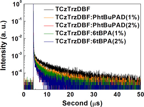
Table 2. The delayed fluorescent lifetime and the PLQY of the films.
The PL quantum yields (PLQYs) of the emitting layer are also summarized in Table . The TCzTrzDBF exhibited a high PLQY of 96.5%, and the addition of the fluorescent emitter did not significantly degrade its PLQY despite the low PLQY of the fluorescent emitter relative to that of the TCzTrzDBF. This indicates that the energy transfer from the TADF compound to the fluorescent emitter efficiently harvests the singlet excitons of the fluorescent emitter with little loss. The PLQY loss at the 2% fluorescent emitter concentration was due to the Dexter energy transfer and direct excitation of the fluorescent emitter.
Based on the photophysical analysis results, the hyper-fluorescent OLEDs were developed by doping the TCzTrzDBF TADF sensitizer and the PhtBuPAD, 6tBPA fluorescent emitters in the DPEPO host. In the emitting layer, the doping concentration of TCzTrzDBF was 20% in the DPEPO host, and the doping concentration of the co-doped TCzTrzDBF: PhtBuPAD or 6tBPA device was 20%: 1% or 2%. The device structures and energy level diagrams are shown in Figure . The current density–voltage-luminance, EQE, and electroluminescence (EL) spectra of the devices are shown in Figure . In the current density–voltage-luminance data, the current density of the devices showed almost the same tendency because the current density would depend on the charge trapping effect on the DPEPO host of the large energy level gap between the DPEPO and the emitter. In particular, most of the carriers would be trapped in the TCzTrzDBF sensitizer due to the high doping concentration of 20%.
Figure 5. Device structure and energy level diagram of the devices.
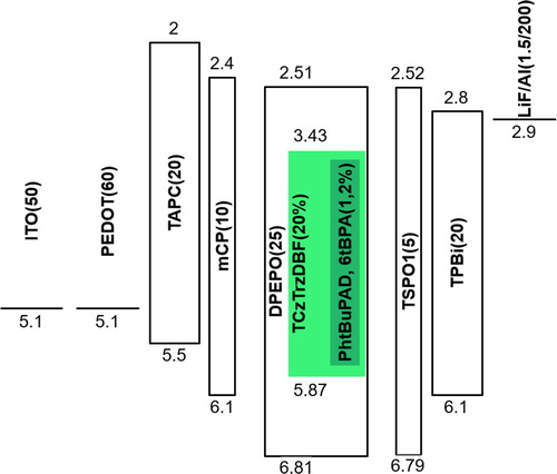
Figure 6. Device performances of the devices: (a) Current density-voltage-luminance curves, (b) EL spectra, (c) EQE-luminance curves, and (d) Current efficiency-luminance curves.
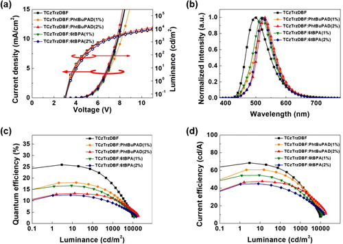
The EL spectra of the devices also showed the same tendency as that of the PL spectra of the films. The spectra of the TCzTrzDBF and PhtBuPAD co-doped devices had the maximum wavelength of 526 nm at the 1% doping concentration, and 528 nm at the 2% doping concentration, which indicate perfect energy transfer at the 2% doping concentration. The spectra of the TCzTrzDBF and 6tBPA co-doped devices had the maximum wavelength of 518 nm at the 1% doping concentration, and 523 nm at the 2% doping concentration. Efficient energy transfer was observed at the 2% doping concentration. Therefore, the EL spectra of the devices were governed by the degree of the Förster energy transfer from the TADF sensitizer to the fluorescent emitters.
The maximum EQE of the TCzTrzDBF device was 26.0%. However, the EQE at 3,000 cd/m2 was 11.6%. There was a huge efficiency roll-off of 55% at high luminance. The long-delayed fluorescent lifetime of the TADF sensitizer could induce the quenching processes of triplet–triplet annihilation (TTA) and triplet-polaron annihilation (TPA) [Citation18–20]. As discussed in the transient PL analysis, the reduced delayed fluorescent lifetime of the co-doped film allowed maximum EQEs of 18.1% and 16.7% in the TCzTrzDBF: PhtBuPAD and TCzTrzDBF: 6tBPA co-doped devices, with the efficiency roll-offs of 47% and 49%, respectively, at the 1% doping concentration of the fluorescent emitters. Although the maximum EQE was slightly reduced due to the Dexter energy transfer from the TADF sensitizer to the fluorescent emitters, the efficiency roll-off was also reduced. In addition, the hyper-fluorescent devices with a 2% doping concentration of the fluorescent emitters showed a low efficiency roll-off compared to those with a 1% doping concentration of the fluorescent emitters in accordance with the delayed fluorescent lifetime in the transient PL analysis. Furthermore, the hyper-fluorescent device with the PhtBuPAD emitter maximized the effect due to the bulky blocking unit of the 2-phenylpropan-2-yl unit. Although the delayed fluorescent lifetime of the co-doped film with the 6tBPA emitter was slightly shorter than that of the co-doped film with the PhtBuPAD emitter, the reduction of the maximum EQE with the increasing doping concentration (concentration quenching) and the EQE roll-off of the hyper-fluorescent device with the PhtBuPAD emitter were much smaller than those of the co-doped film with the 6tBPA emitter [Citation21]. The maximum EQE of the hyper-fluorescent device with the PhtBuPAD emitter was 13.3% with an efficiency roll-off of 32% at the 2% doping concentration of the fluorescent emitter. Despite the high PLQY of the fluorescent emitter co-doped emitting layer, the EQE of the hyper-fluorescent device was degraded because of the direct charge injection into the fluorescent emitters and the Dexter energy transfer to the fluorescent emitter. Although the PLQY of 6tBPA was higher than that of PhtBuPAD, the molecular structure of 6tBPA made it more difficult for it to suppress the Dexter energy transfer than for PhtBuPAD. The Dexter energy transfer was the main loss mechanism of the hyper-fluorescent devices. The current efficiency of the hyper-fluorescent device with the PhtBuPAD emitter was even higher than that of the TCzTrzDBF doped device at 3,000 cd/m2. These results verified that the bulky blocking unit of the fluorescent emitter has a huge effect in suppressing Dexter energy transfer and minimizing efficiency roll-off in hyper-fluorescent OLEDs. The performance of the devices is summarized in Table .
Table 3. The device performances of the hyper-fluorescent OLED.
3. Conclusion
The hyper-fluorescent devices with the TCzTrzDBF TADF sensitizer and the PhtBuPAD fluorescent emitter were efficacious in achieving a high EQE of 18.1% with a low efficiency roll-off. Utilization of fluorescent emitters for hyper-fluorescent OLEDs could efficiently reduce the delayed fluorescent lifetime of the TADF sensitizer. In addition, the usage of the PhtBuPAD emitter as the fluorescent emitter with a bulky blocking unit could suppress Dexter energy transfer from the TADF sensitizer to the fluorescent emitter and concentration quenching, compared to other OLEDs. This study showed the direction of the development of future hyper-fluorescent OLEDs.
4. Experimental methodology
The devices had a structure of ITO (50 nm)/PEDOT:PSS (60 nm)/TAPC (20 nm)/mCP (10 nm)/emitting layer (25 nm)/TSPO1 (5 nm)/TPBi (20 nm)/LiF (1.5 nm)/Al (200 nm). The emitting layer was a DPEPO host doped with a TCzTrzDBF TADF sensitizer (with a 20 wt% doping concentration) and 6tBPA, PhtBuPAD fluorescent emitters (with 1 and 2 wt% doping concentrations). In the device structure, ITO is indium tin oxide; PEDOT:PSS is Poly(3,4-ethylenedioxythiophene):poly(styrenesulfonate); TAPC is 4,4‘-Cyclohexylidenebis[N,N-bis(4-methylphenyl)aniline]; mCP is 1,3-Bis(N-carbazolyl)benzene; TSPO1 is Diphenyl[4-(triphenylsilyl)phenyl]phosphine oxide; and TPBi is 2,2’,2"-(1,3,5-Benzinetriyl)-tris(1-phenyl-1-H-benzimidazole).
PEDOT:PSS was spin-coated onto ITO glass, and the vacuum thermal evaporation process at a vacuum pressure of 5×10⁻⁷ Torr was used to fabricate the devices. The device characterization was carried out using a Keithley 2400 source meter for the voltage scan and current density collection, and a CS2000 spectroradiometer for the optical output measurement.
Disclosure statement
No potential conflict of interest was reported by the author(s).
Additional information
Notes on contributors

Won Jae Chung
Won Jae Chung received his bachelor’s degree in 2019 from the School of Chemical Engineering of Sungkyunkwan University, Korea. Currently, he is a Master’s degree candidate at the School of Chemical Engineering of Sungkyunkwan University. His major research area is the development of a novel device structure for organic electronic devices for high performance.

Jun Yeob Lee
Jun Yeob Lee received his PhD degree from Seoul National University, Korea in 1998. After a postdoctoral teaching stint at Rensselaer Polytechnic Institute from 1998 to 1999, he joined Samsung SDI and developed active matrix organic light emitting diodes for six years. Then he worked as a professor at the Department of Polymer Science and Engineering of Dankook University. He has been a professor at the School of Chemical Engineering of Sungkyunkwan University since 2015. His main research areas are the synthesis of organic electronic materials and the development of a novel device structure for organic electronic devices.
References
- C.W. Tang, and S.A. VanSlyke, Appl. Phys. Lett 51 (12), 913–915 (1987).
- C.W. Tang, S.A. VanSlyke, and C.H. Chen, J. Appl. Phys 65 (9), 3610–3616 (1989).
- M. Zhu, and C. Yang, Chem. Soc. Rev 42 (12), 4963–4976 (2013).
- M.A. Baldo, D.F. O'Brien, Y. You, A. Shoustikov, S. Sibley, M.E. Thompson, and S.R. Forrest, Nature 395 (6698), 151–154 (1998).
- A. Endo, K. Sato, K. Yoshimura, T. Kai, A. Kawada, H. Miyazaki, and C. Adachi, Appl. Phys. Lett 98 (8), 083302 (2011).
- Q. Zhang, B. Li, S. Huang, H. Nomura, H. Tanaka, and C. Adachi, Nat. Photonics 8 (4), 326–332 (2014).
- A. Endo, M. Ogasawara, A. Takahashi, D. Yokoyama, Y. Kato, and C. Adachi, Adv. Mater 21 (47), 4802–4806 (2009).
- S. Park, O.-H. Kwon, Y.-S. Lee, D.-J. Jang, and S.Y. Park, J. Phys. Chem. A 111 (39), 9649–9653 (2007).
- H. Nakanotani, T. Furukawa, T. Hosokai, T. Hatakeyama, and C. Adachi, Adv. Opt. Mater 5 (12), 1700051 (2017).
- W. Song, I. Lee, and J.Y. Lee, Adv. Mater 27 (29), 4358–4363 (2015).
- D. Zhang, L. Duan, C. Li, Y. Li, H. Li, D. Zhang, and Y. Qiu, Adv. Mater 26 (29), 5050–5055 (2014).
- D.L. Dexter, The J. Chem. Phys 21 (5), 836–850 (1953).
- M. Inokuti, and F. Hirayama, J. Chem. Phys 43 (6), 1978–1989 (1965).
- S.H. Han, and J.Y. Lee, J. Mater. Chem. C 6 (6), 1504–1508 (2018).
- D. Zhang, X. Song, M. Cai, and L. Duan, Adv. Mater 30 (6), 1705250 (2018).
- J.G. Yu, S.H. Han, H.L. Lee, W.P. Hong, and J.Y. Lee, J. Mater. Chem. C 7 (10), 2919–2926 (2019).
- Y.H. Lee, S. Park, J. Oh, S.-J. Woo, A. Kumar, J.-J. Kim, J. Jung, S. Yoo, and M.H. Lee, Adv. Opt. Mater 6 (17), 1800385 (2018).
- K. Masui, H. Nakanotani, and C. Adachi, Org. Electron 14 (11), 2721–2726 (2013).
- X. Cai, X. Li, G. Xie, Z. He, K. Gao, K. Liu, D. Chen, Y. Cao, and S.-J. Su, Chem. Sci 7 (7), 4264–4275 (2016).
- D. Zhang, C. Zhao, Y. Zhang, X. Song, P. Wei, M. Cai, and L. Duan, ACS Appl. Mater. Interfaces 9 (5), 4769–4777 (2017).
- C. Rothe, C.-J. Chiang, V. Jankus, K. Abdullah, X. Zeng, R. Jitchati, A.S. Batsanov, M.R. Bryce, and A.P. Monkman, Adv. Funct. Mater 19 (13), 2038–2044 (2009).