
ABSTRACT
We report on bilayer dichroic dye-doped liquid crystal (BDLC) films for patternable color codes, which can be used in anti-counterfeiting applications such as security codes and, unlike the conventional single-layer LC color films, show unique color changes depending on the direction of the polarization of the incident light that passes through them. This is a facile way to enhance the security level of security codes. BDLC films are fabricated by laminating two single-layer LC polymer network films with crossed optical axes. We believe that BDLC films can be used as a new platform for a security-enhanced anti-counterfeiting code that can replace complex chiral materials or expensive plasmonic particles.
1. Introduction
Polarization-dependent liquid crystal (LC) films have been applied in broad fields, including in LC polarizers [Citation1–5], photo-luminescence films [Citation6–8], and photonic crystals [Citation9–11]. Among these, dye-doped LC films composed of coaligned LC polymer networks and dichroic dyes attract interest among researchers due to their novel optical property and efficient fabrication process [Citation1–7,Citation12–19]. These films, also called ‘host–guest LC films,’ absorb maximum light when the polarization direction of the incident linear polarized light (LPL) and the absorption axes of the dichroic dyes are parallel. Using this unique property, this platform has been studied for diverse applications such as light-responsive polymers [Citation14,Citation15], smart window [Citation16,Citation17], and coatable polarizers [Citation3,Citation4].
Although previous studies have suggested security uses for dichroic dye-doped LC films [Citation18,Citation19], they were able to show only an ‘on and off’ function with low security. This conventional film could show a difference in brightness depending on the direction of the incident LPL because almost all dichroic dyes have only one absorption axis, except in special cases [Citation20,Citation21]. To overcome this limitation, chiral photonic crystals [Citation11] or materials that use refractive index change [Citation22] have been proposed, but this method requires expensive and complicated fabrication methods.
In this study, we suggest the use of a bilayer dichroic dye-doped LC (BDLC) film as an anti-counterfeiting film with enhanced security. BDLC films have two types of aligned dichroic dye-doped LC films with different absorption wavelengths. These two LC films are laminated. Thus, each film perpendicularly crosses the absorption axis of the other film [Citation23]. BDLC films show different transmission colors, not a different brightness from that of the conventional single-layer films, when the direction of the incident LPL changes. These transmission color changes are analyzed with an optical microscope, and a traditional photolithography process is used to show that the BDLC film can be utilized as a patternable anti-counterfeiting code.
2. Experiment method
2.1. Materials
The LC mesogen, ST04321, was purchased from Synthon Chemicals in Germany. The planar anchoring polyimide (PAPI), PIA-5550-02A, was purchased from the JNC Corporation in Japan. The photo-initiator (2,2-dimethoxy-2-phenyl acetophenone) and the inhibitor (butylated hydroxytoluene) were purchased from Sigma-Aldrich in the USA. The anthraquinone derivative cyan dichroic dye was purchased from Nematel GmbH in Germany. The bis-azobenzene derivative red dichroic dye was synthesized according to a previous research [Citation23].
2.2. Sample preparation
To fabricate the BDLC film, the O2 plasma-treated glass substrates were coated with PAPI using a spin coater (4000 rpm for 40 s), and baked for 2 h at 200°C. After the baking process, the PAPI-coated glass was rubbed. A sandwich cell was fabricated with two PAPI-treated glass substrates, and 5 μm silica spacers dispersed in the UV-curable glue. The LC mesogen was mixed with 3 wt % each of the red and cyan dichroic dyes, 1 wt % of the photo-initiator, and 0.5 wt % of the inhibitor.
2.3. Characterization
The optical images and LC textures were obtained using two polarized optical microscopes (Nikon Eclipse LV100 POL and Nikon Eclipse Ti2-E). The phase transition temperatures of the LC mixtures were measured with a differential scanning calorimeter (Q2000, TA Instruments). The temperature was controlled with a heating stage (LTS420, Linkam).
3. Results and discussion
3.1. Fabrication of the BDLC film
The BDLC film was fabricated on glass treated with PAPI. The fabrication process is as follows (Figure (a)). (i) Two kinds of dichroic dyes that absorb different wavelengths were prepared: bis-azo benzene dye, synthesized following previous research [Citation23] and denoted as ‘red,’ and anthraquinone derivative dye, denoted as ‘cyan.’ In this study, a reactive mesogen that showed both nematic and smectic phases was used to fabricate the LC films (Figure (b,c)). It has been reported in previous studies [Citation2,Citation4] that when a reactive mesogen is polymerized in the smectic phase, its optical properties and molecular alignment are significantly improved compared to the film polymerized in the nematic phase.
Figure 1. (a) Schematic illustrations of the BDLC film fabrication methods. (b) Molecular structure and differential scanning calorimetry curve of the reactive mesogen. (c) Polarized optical microscope images of the LC textures. The red and blue arrows indicate the alignment direction of the ‘red’ layer and the ‘cyan’ layer, respectively. The white arrows indicate the polarizer (P) and the analyzer (A). Scale bar = 100 μm.
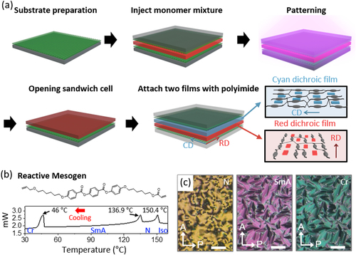
The reactive mesogen was mixed with 3 wt % of the red or cyan dyes, 1 wt % of the photo-initiators, and 0.5 wt % of the inhibitors to prevent its unexpected thermal polymerization. (ii) A sandwich cell with two uniaxially rubbed PAPI-coated glass substrates was prepared to fabricate a ‘red’ single-layer film. (iii) The ‘red’-based mixture was injected into the sandwich cell at 155°C, which is the isotropic temperature of LC mixtures, and cooled to 25°C at a rate of 10°C/min. The cooling rate was controlled because at high cooling rates, the smectic layer may be distorted and unintentional thermal curing may occur. (iv) The LC mixture was polymerized using UV light with a power of ∼1.23 mW/cm2 for 30 min at 25°C (Cr phase). The molecular arrangement of reactive mesogens does not change even when they are polymerized in the Cr phase [Citation23], so photo-polymerization was carried out in the Cr phase with the highest molecular alignment. (v) The sandwich cell was opened and the unpolymerized parts were developed with ethanol and washed with water. (vi) A ‘cyan’ single-layer film was fabricated using the same method as that in (ii-v). (vii) To laminate the ‘cyan’ film on the ‘red’ film, the PAPI solution was spin-coated on the red film. (viii) Finally, the ‘cyan’ film was placed on the PAPI-coated ‘red’ film. The absorption axes of the two films were aligned using an optical microscope to make them perpendicular to each other. (ix) The resultant bilayer film was curried at 90°C for 10 min.
3.2. Optical investigation of the BDLC film
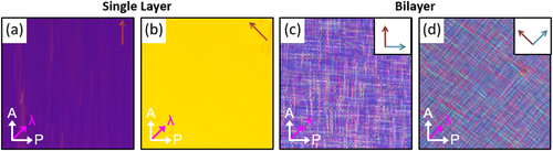
The optical properties of the BDLC film were investigated with a polarized optical microscope. First, the texture of the ‘red’ single-layer film was observed under the crossed polarizer in which a full-wave plate (λ = 530 nm) was inserted. It was observed that the smectic LC polymer was uniformly aligned along the rubbing direction (red arrow) while maintaining its liquid crystalline structure even after the polymerization process (Figure (a,b)). When the BDLC film, which had perpendicular optic axes (Figure (c,d)), was observed with a polarized microscope, the images showed that the LC film in each layer maintained its alignment (red and blue arrow) with each rubbing direction and that the LC structures of the films were not destroyed and were well maintained after the lamination process.
Figure 2. Polarized optical microscope images with a full-wave plate (λ = 530 nm) of (a) and (b) the uniaxially aligned single-layer dichroic dye-doped LC film (‘red’), and (c) and (d) the BDLC film. The white arrows indicate the polarizer (P) and the analyzer (A). The magenta arrow indicates the slow axis of the full-wave plate. Scale bar = 100 μm.
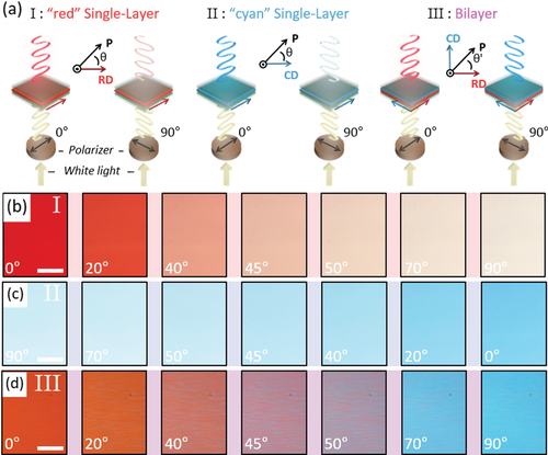
To observe the optical properties of the BDLC film according to its polarization dependency, the difference in its transmission color according to the direction of the incident LPL was investigated using an optical microscope in which one polarizer was inserted. the angle between the absorption axis of the polymer film and the polarization direction of the incident LPL in the single-layer film is depicted as θ. When θ increased, the absorbance of the ‘red’ and ‘cyan’ single-layer film decreased because of the direction of the polarization of the incident LPL, and the absorption axes of the red and cyan dyes were no longer parallel (Figure (a–c)). As a result, as θ changed from 0° to 90°, the observed transmission color of each film changed from red and cyan to almost transparent. These results are the same as those for the conventional dichroic dye-doped LC films [Citation1–7,Citation12–19]. However, when their optical axes were stacked in a crossed manner, the transmission color changed differently from that of the single-layer film (Figure (a,d)). When θ’, the angle between the absorption axis of the ‘red’ layer and the direction of the polarization of the incident LPL, increased, the transmission color changed from red to purple to cyan. These color changes were due to the two perpendicularly aligned absorption axes. The absorbance in the ‘red’ layer decreased because the polarization direction of the incident light, and the absorption axis of the ‘red’ layer were no longer parallel as θ’ became 90°. At the same time, the absorbance of the ‘cyan’ layer increased because the polarization direction of the incident light and the absorption axis of the ‘cyan’ layer became closer to parallel [Citation23]. (Figure ).
Figure 3. (a) Schematic illustration of the polarization dependency of the single-layer dichroic dye-doped LC films and the BDLC film. Optical microscope images of the transmission color change of the (b) ‘red’ single-layer film, (c) ‘cyan’ single-layer film, and (d) BDLC film, when θ was varied. Scale bar = 100 μm.
3.3. Patternable security code
In the photopolymerization process, fine patterns can be easily fabricated through selective light exposure using a photomask [Citation3,Citation24]. Thus, this process improves the security of anti-counterfeiting codes compared to the existing dichroic dye-doped film [Citation18,Citation19]. When unpolarized light passed through patterned BDLC films, it is divided into LPLs that oscillate perpendicularly at different wavelengths because of the selective absorption of each layer (Figure (a)). When the transmitted LPLs were observed directly without any optical component, only the color mixed with red dye and cyan dye was seen. However, when they were observed with an analyzer, it was seen that their transmission colors varied depending on the φ (the angle between the analyzer and the absorption axis of the ‘red’ layer) due to the perpendicularly divided LPLs. As shown in Figure (b,c), the letters ‘LG’ in the ‘red’ layer, which had a line width of ≈ 60 μm, and the uniaxially aligned ‘cyan’ layer were fabricated using the same method as that described above. The ‘cyan’ film was stacked on the ‘red’ layer so that the absorption axes would be perpendicularly aligned (Figure (b,c)). The resulting films were observed while rotating the analyzer. When φ was 0°, the reddish letters ‘LG’ were seen (Figure (b)), but when φ became 90° [Figure (c)], the letters could not be clearly observed.
Figure 4. (a) Schematic illustration of the transmitted LPLs through the patterned BDLC film. Optical microscope images of the patternable codes with the letters ‘LG’ when (b) φ = 0° or (c) φ = 90°. Optical microscope images of the transmission color change observed in a security code patterned with the letters ‘KAIST’ without (f) an analyzer or when (d) φ = 0° or (e) φ = 90°. Scale bar: (b) and (c) = 1 mm and (d)–(f) = 5 mm.
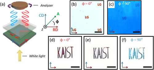
Similarly, a BDLC film was fabricated on both the ‘red’ and ‘cyan’ layers of which the letter ‘KAIST’ was patterned [Figure (e)–(g)]. When the letters were observed without an analyzer [Figure (f)], the purple color was seen because both the red and cyan LPLs could be transmitted through the film. However, when the analyzer was introduced, the red transmission color [Figure (e)] was observed for φ = 0°and the cyan transmission color was observed for φ = 90° [Figure (g)] due to the selective LPL transmission of each layer.
4. Conclusion
In this study, we fabricated a patternable BDLC film via photolithography of a dichroic dye-doped LC film that exhibited an interesting polarization dependency. When the direction of the incident LPLs that passed through the film were varied, or when the film was observed by rotating the analyzer, various transmission color changes were observed depending on the rotation of the polarization components. This unique optical property and pattern-availability of BDLC films can make them useful as security codes that are difficult to mimic. Although only red and cyan dyes were proposed in this experiment, if dichroic dyes are appropriately selected, various color combinations are possible [Citation3]. Moreover, it is expected that a film with dynamic color changes can be fabricated using additional LCs and electric fields in the future [Citation7,Citation8]. Finally, it is expected that an optical film with a three-dimensional director configuration or with chiral properties introduced can be achieved when various liquid crystal properties are applied [Citation25–27].
Acknowledgments
This study was supported by LG Display under the LGD-KAIST Incubation Program and by a grant from the National Research Foundation funded by the Korean Government through the Ministry of Science and Information Technology (2017R1E1A1A01072798 and 2018R1A5A1025208).
Disclosure statement
The authors declare no competing financial interest.
Additional information
Funding
Notes on contributors

Geonhyeong Park
Geonhyeong Park received his B.S. degree from the Department of Organic and Nanoengineering of Hanyang University in Seoul, South Korea in 2018, and his integrated M.S and Ph.D. degrees from the the Department of Chemistry of KAIST in Daejeon, South Korea. His main research areas are topological liquid crystal defect engineering and liquid crystal polymers.

Dong Ki Yoon
Dong Ki Yoon received his Ph.D. degree in Chemical and Biomolecular Engineering from KAIST in 2007. After working on the next-generation nanofabrication project in Samsung Electronics Co. for two years, he conducted postdoctoral research on the novel phenomena of liquid crystals in marginal space and laser-induced defects of liquid crystals at the Department of Physics of the University of Colorado in Boulder, Arizona, USA. Then in 2011, he joined KAIST, where he currently leads the Soft Materials Assembly team for patterning and display applications based on soft materials such as liquid crystals, supramolecules, biomaterials, and polymers.
References
- P. J. Shannon, W. M. Gibbons, S. T. Sun, Nature. 368, 532–533 (1994). doi:https://doi.org/10.1038/368532a0.
- P. Emiel, L. Johan, A.M. S. Jan, D. J. Broer, Adv. Mater. 18, 2412–2417 (2006). doi:https://doi.org/10.1002/adma.200600355.
- G. Myhre, A. Sayyad, S. Pau, Opt. Express. 18, 27777 (2010). doi:https://doi.org/10.1364/OE.18.027777.
- R. He, E. Oh, Y. Ye, P. Wen, K.-U. Jeong, S. H. Lee, X.-D. Li, M.-H. Lee, Polymer. 176, 51–59 (2019). doi:https://doi.org/10.1016/j.polymer.2019.05.032.
- P. Im, D.-G. Kang, D.-Y. Kim, Y.-J. Choi, W.-J. Yoon, M.-H. Lee, I.-H. Lee, C.-R. Lee, K.-U. Jeong, ACS Appl. Mater. Interfaces. 8, 762–771 (2016). doi:https://doi.org/10.1021/acsami.5b09995.
- Y. He, J. Li, J. Li, C. Zhu, J. Guo, ACS Appl. Polym. Mater. 1, 746–754 (2019). doi:https://doi.org/10.1021/acsapm.8b00276.
- M.-J. Gim, D. K. Yoon, ACS Appl. Mater. Interfaces. 8, 27942–27948 (2016). doi:https://doi.org/10.1021/acsami.6b10762.
- M.-J. Gim, S. Turlapati, S. Debnath, N. V. S. Rao, D. K. Yoon, ACS Appl. Mater. Interfaces. 8, 3143–3149 (2016). doi:https://doi.org/10.1021/acsami.5b10554.
- M. Mitov, Adv. Mater. 24, 6260–6276 (2012). doi:https://doi.org/10.1002/adma.201202913.
- A. Tran, C. E. Boott, M. J. MacLachlan, Adv. Mater. 32, 1905876 (2020). doi:https://doi.org/10.1002/adma.201905876.
- W. Park, T. Ha, T. S. Jung, K. I. Sim, J. H. Kim, J. M. Wolska, D. Pociecha, E. Gorecka, T.-T. Kim, D. K. Yoon, Nanoscale. 12, 21629–21634 (2020). doi:https://doi.org/10.1039/D0NR03743E.
- W. Zhang, L. Zhang, X. Liang, L. Zhou, J. Xiao, L. Yu, F. Li, H. Cao, K. Li, Z. Yang, H. Yang, Sci Rep. 7, 42955 (2017). doi:https://doi.org/10.1038/srep42955.
- E. I. L. Jull, M. Wahle, P. J. M. Wyatt, C. Ellis, S. J. Cowling, J. W. Goodby, K. Usami, H. F. Gleeson, Opt. Express. 27, 26799 (2019). doi:https://doi.org/10.1364/OE.27.026799.
- D. Martella, S. Nocentini, F. Micheletti, D. S. Wiersma, C. Parmeggiani, Soft Matter. 15, 1312–1318 (2019). doi:https://doi.org/10.1039/C8SM01954A.
- Y. Li, Y. Liu, D. Luo, Adv. Opt. Mater., 2001861 (2020). doi:https://doi.org/10.1002/adom.202001861.
- B.-H. Yu, J.-W. Huh, K.-H. Kim, T.-H. Yoon, Opt. Express. 21, 29332 (2013). doi:https://doi.org/10.1364/OE.21.029332.
- S.-W. Oh, S.-H. Kim, T.-H. Yoon, J. Mater. Chem. C. 6, 6520–6525 (2018). doi:https://doi.org/10.1039/C8TC01368C.
- C. Carrasco-Vela, X. Quintana, E. Otón, M. Geday, J. Otón, Opto-Electron. Rev. 19 (2011), doi:https://doi.org/10.2478/s11772-011-0049-8.
- R. Yamaguchi, Proc. SPIE. 7232. doi:https://doi.org/10.1117/12.805229.
- M. G. Debije, C. Menelaou, L. M. Herz, A. P. H. J. Schenning, Adv. Opt. Mat. 2, 687–693 (2014). doi:https://doi.org/10.1002/adom.201400132.
- A. G. Bé, C. Tran, R. Sechrist, J. J. Reczek, Org. Lett. 17, 4834–4837 (2015). doi:https://doi.org/10.1021/acs.orglett.5b02399.
- J. H. Ko, Y. J. Yoo, Y. J. Kim, S. Lee, Y. M. Song, Adv. Funct. Mater. 30, 1908592 (2020). doi:https://doi.org/10.1002/adfm.201908592.
- G. Park, Y.-S. Choi, H. S. Yun, D. K. Yoon, ACS Appl. Mater. Interfaces. 12, 45315–45321 (2020). doi:https://doi.org/10.1021/acs.chemmater.0c00669.
- D.-G. Kang, M. Rim, H. Ko, J. Koo, S.-I. Lim, M. Park, W.-J. Yoon, Y.-J. Choi, K.-U. Jeong, Chem. Mater. 32, 7630–7638 (2020). doi:https://doi.org/10.1021/acs.chemmater.0c00669.
- D. S. Kim, Y. J. Cha, M. H. Kim, O. D. Lavrentovich, D. K. Yoon, Nat Commun. 7, 10236 (2016). doi:https://doi.org/10.1038/ncomms10236.
- D. S. Kim, D. K. Yoon, J. Inf. Display. 19, 7–23 (2018). doi:https://doi.org/10.1080/15980316.2017.1410500.
- G. Park; S. Čopar; A. Suh, M. Yang, U. Tkalec, D. K. Yoon, ACS Cent. Sci. 6, 1964–1970 (2020). doi:https://doi.org/10.1021/acscentsci.0c00995.