
 ?Mathematical formulae have been encoded as MathML and are displayed in this HTML version using MathJax in order to improve their display. Uncheck the box to turn MathJax off. This feature requires Javascript. Click on a formula to zoom.
Abstract
This paper investigates the optical seamlessness of a holographic multi-vision display. The purpose of the multi-vision approach is to scale up the resolution of a holographic display without requiring a single extremely high-resolution spatial light modulator. Optical experiments reveal that a holographic multi-vision system with 16M pixel resolution successfully generates a seamless virtual reference plane with the essential optical characteristics of a holographic display, such as the accommodation effect and binocular parallax. It is realized from a matrix of eight (42) high-resolution transmission-type liquid crystal displays. Theoretical analysis and numerical simulations are presented for the proposed seamless holographic multi-vision system.
1. Introduction
Holography is generally considered as an ultimate three-dimensional (3D) display technology because holographic displays can provide essential 3D cues such as accommodation-vergence matching and continuous motion parallax [Citation1]. However, many challenges still remain in the commercial development of holographic displays, including the limited capability of spatial light modulators (SLMs), which are necessary for modulating the optical wave field. Most SLMs have insufficient space-bandwidth product (SBP) [Citation2] in terms of information required for the application of holographic 3D displays. A more stringent approach to improving the SBP is to fabricate an extremely large-scale high-resolution SLM.
Despite this practical limitation, several approaches to improving SBP have been proposed in recent decades. One of these approaches is a holographic display system that makes use of multiple SLMs. For example, Fukaya et al. demonstrated a holographic display that eliminates vertical parallax and extends the horizontal viewing angle by tiling a number of SLMs in the horizontal direction [Citation3, Citation4]. Hahn et al. also proposed a holographic display system with a wide viewing angle using a curved array of multiple SLMs [Citation5], in which three sub-SLMs were diagonally positioned in contact with each other and their viewing field was continuously extended without interruption. Kozacki et al. proposed a holographic display with an extended viewing angle achieved by arranging multiple tilted SLMs in a circular configuration [Citation6]. In the curved array configuration of the SLMs, a curved lens array was used to generate a dynamic holographic stereogram with a wide viewing angle. Meanwhile, Sakai et al. reported a novel method for realizing full parallax video holography by using 16 (44) reflection-type SLMs in a planar configuration [Citation7, Citation8]. Here, tiling multiple reflection-type SLMs limits their number due to the multiple bulky beam splitters required to illuminate and combine the SLMs. On the other hand, the multi-vision system is commonly used in the display industry to realize large-sized display [Citation9]. Our multi-vision system is composed of multiple transmission-type liquid crystal displays (LCDs). Transmission-type SLMs are more suitable for scaling up holographic displays because complex optics are not required between the multi-vision system and the observer.
A common problem found in holographic multi-vision systems is the annoying seams between adjacent SLMs. In a multi-vision configuration, the bezel of each SLM represents an obstacle in producing a continuous image. Several strategies have been proposed in order to remove the seams. For example, directly applying cylindrical lens pairs to the seams can conceal the seam region and generate a continuous holographic image [Citation10]. However, using a refractive optical element, such as a cylindrical lens, to remove the seams causes image distortion, and it is only useful for specific viewing angles. Other approaches include combining a digital holographic display consisting of multiple SLMs with a large-area directional diffractive element composed of pixelated gratings [Citation11] and effectively using multiple SLMs to increase the size of the reconstructed image [Citation12].
In this paper, we propose a simple method for eliminating the annoying seams and generating seamless holographic images on the virtual reference plane of a transmission-type holographic multi-vision system. Holographic technique is expected to reduce the visibility of the seam between SLMs; however, to our knowledge, there have been no studies to clarify the requirements for creating the seamless multi-vision system. We not only define a minimum distance of a seamless virtual reference plane by using the uniformity of intensity contrast of the seam in the retina of the eye, but we also mathematically describe the relationship between the minimum distance of the seamless virtual reference plane and the viewing distance. We present a 16M pixel resolution holographic multi-vision system consisting of a matrix of eight (42) high-resolution transmission-type LCDs. A seamless computer-generated hologram (CGH) image is synthesized on the virtual plane between the SLM plane and the viewer. Section 2 describes the proposed transmission-type binocular holographic multi-vision system and CGH synthesis algorithm for the generation of binocular full color holographic images. Section 3 outlines an experiment for the analysis and verification of the generation of seamless holographic 3D images with a natural accommodation effect. Section 4 presents the conclusion and future directions.
2. Transmission-type binocular holographic multi-vision system
For the practical implementation of the proposed binocular holographic multi-vision system, a tiling-type multi-vision approach that spatially arranges several commercial LCDs within the same plane is used in order to increase the SBP. In our experimental setup, the multi-vision system is composed of a 42 matrix, and eight driving boards that control each LCD are mounted outside the active area.
This system employs a 5-inch transmission-type commercial LCD with full color FHD resolution and opaque bezels including the gate driving circuit and metal electrodes (Figure [a]). These bezels create rectangular seam lines inside the multi-vision configuration (Figure [b]), thus leading to discontinuous images and lower image quality of the resulting multi-vision display. It is difficult to completely remove the seam in the display image of a multi-vision system. The experimental setup is presented in Figure (c). We use an RGB light-emitting diode (LED) system to illuminate the multi-vision system. The system parameters are shown in Table . The central wavelengths of the RGB LED system are 640, 525, and 450 nm, respectively. The multi-vision system consists of eight SLMs, has a diagonal size of 13.13 in., and has a total of approximately 16M pixels. The size of the viewing window generated by this system is 2828
. Figures (d), (e), and (f) present the 4
2 LCD multi-vision section, the RGB LED light sources, and the optical components of the system (i.e. the parabolic mirror and beam splitter). The parabolic mirror used as a field lens has a focal length of 1.8 m, and the viewing distance in the multi-vision system is 3.6 m, which is twice the focal length [Citation13]. A dichroic prism is used to combine the RGB beams.
Figure 1. Rendering images of (a) a commercial LCD with a bezel and (b) the 42 multi-vision display with seams, (c) the experimental set-up for the system, (d) the
multi-vision, (e) the light sources, and (f) the optical components including the parabolic mirror and beam splitter.
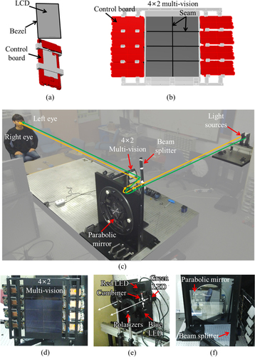
Table 1. System parameters.
A CGH synthesis algorithm is developed for the binocular full color holographic multi-vision system [Citation14], and the reconstruction characteristics are analyzed. The CGH multiplexes left and right holographic views in order to produce a binocular parallax. Each view provides an accommodation effect for a single eye.
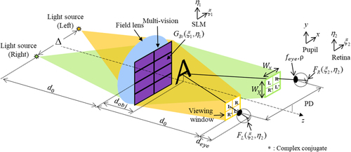
Figure displays a schematic diagram of the forward and backward cascaded Fresnel transform model considering both eyes of the observer in a holographic multi-vision system. The CGH wave field, , on the SLM plane propagates to the retina plane, obtaining the wave fields on the retina plane of the left eye,
, and right eye,
. The binocular CGH pattern,
, is a multiplexed hologram of the left 3D perspective wave field,
, and right 3D perspective wave field,
. The mathematical relationship between a wave field on the SLM plane,
and a wave field on the retina plane,
, is described by the forward cascaded and inverse cascaded Fresnel transforms [Citation15, Citation16] (Appendix).
Figure 2. Forward and inverse cascaded Fresnel transform model considering both eyes of the observer in a holographic multi-vision system.
We focus on the compact multiplexing of and
into
. The left and right stereoscopic holographic images are multiplexed in a square viewing window by using the pupil space division method [Citation17]. The binocular CGH pattern on the SLM plane is expressed as
(1)
(1) Here,
denotes carrier frequency along the
axis for left (right) view. For the synthesis of
, the carrier wave field patterns,
and
, are multiplied to
and
in order to synthesize the left and right images within the square viewing window. The size of the viewing window in the pupil plane,
, can be obtained as
(2)
(2) where
is the wavelength of the light,
is the observation distance from the SLM, and
and
denote the pixel pitch of the LCD in the horizontal and vertical directions, respectively. The vector components of the appropriate carrier wave field patterns are given by
(3)
(3) In an ideal environment, the viewing window should be at least larger than the size of the human pupil in order to display a holographic image without losing optical information. Since we are using an amplitude-only SLM, the size of the viewing window should be at least twice the size of the pupil in order to exclude the inevitable conjugate area. In addition, the left and right directional RGB LED sources generate two independent viewing windows. The inter-pupil distance,
, and the horizontal length of viewing window are used to determine the interval between the left and right light sources,
. Since the distance from the SLM plane to the light sources and the distance from the SLM plane to the pupil plane are equal to
, the interval between the right and left light sources,
, is given by
(4)
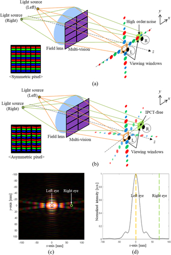
(4) The inter-pupil crosstalk (IPCT) effect should also be considered in the design of the binocular holographic multi-vision system. The IPCT effect is caused by the higher-order diffraction of the pixel structure. Higher-order diffraction patterns are heavily influenced by the shape of the SLM pixel. Square pixels generate a right-angle cross-shaped higher-order diffraction distribution. This distribution for the left view has a strong possibility of spreading across the pupil plane and interfering with the right view (Figure [a]). In contrast, pixels with an asymmetric parallelogram shape generate a scissors-like diffraction pattern in the pupil plane (Figure [b]). This special diffraction pattern deviates the right eye from the high-energy region, thus minimizing IPCT. Figure (c) displays the diffraction pattern distribution including the higher-order terms for the left view in the pupil plane. The two circles in Figure (c) represent the left and right eyes with a pupil diameter of 5.5 mm, an inter-pupil distance of 65 mm, and a distance between the pupil and the SLM of 3.6 m. The intensity distribution of the diffraction pattern along the x-axis is compared in Figure (d). The numerical simulations in Figures (c) and (d) show that the asymmetric pixel architecture differentiates the bright and dark regions, thus allowing the finite right eye pupil to reject the higher-order diffraction crosstalk and reducing the IPCT effect. The same results are observed for the right view. An LCD with an asymmetric parallelogram shape pixel (Figure [b]) was used to set up the experimental testbed for IPCT-free binocular full color holographic multi-vision system, as presented in Figure .
Figure 3. IPCT caused by (a) symmetric and (b) asymmetric pixel architectures in a binocular holographic multi-vision system, (c) diffraction pattern for the asymmetric pixel structure on the pupil plane, and (d) the intensity distribution of the diffraction pattern about the central axis of both eyes.
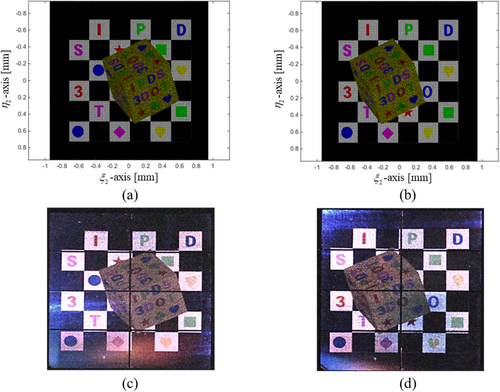
The numerical and optical experiment results for the binocular full color holographic image produced by the multi-vision configuration are shown in Figure . A chessboard background and a die are used as target 3D images. The chessboard is located at the SLM plane, and the die is positioned 0.5 m in front of the chess board. The numerical binocular observation results for the left and right holographic images of the 3D scene on the retina plane are presented in Figures (a) and (b), respectively, while Figures (c) and (d) present the experimental results with binocular parallax for both eyes.
Figure 4. The numerical observation results from the full color multi-vision system with binocular parallax for the (a) reconstructed left 3D perspective image, (b) reconstructed right 3D perspective image, and experimental results for (c) a left 3D perspective image and (d) a right 3D perspective image.
3. Seamless holographic image generation
It is possible to observe a seamless holographic image in our proposed multi-vision system because the holographic image is reconstructed on the object plane via the CGH on the SLM plane, where the seams are physically present. In our multi-vision configuration, the wave field pattern, , on the SLM plane is represented by a complex field with the 4×2 seam mask pattern,
as follows:
(5)
(5) and
(6)
(6) Here,
indicate the horizontal and vertical size of the active area of the SLM,
denotes the width of the seam, and
is the rectangular function. The main screen is separated from the physical SLM array, and the defocusing effect of the SLM can be used to specify a virtual plane for representing seamless holographic 3D images.
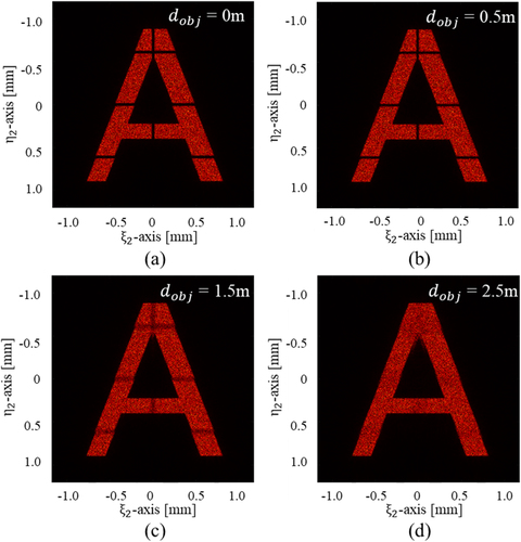
The numerical observation results for a reconstructed holographic image on the object plane for various propagation distances in the proposed multi-vision configuration are shown in Figure . Furthermore, the CGH patterns generate an in-focus image of the letter A on each virtual screen, while dark seam lines are apparent in the numerically reconstructed holographic image. However, the contrast of the seam lines becomes blurred with the distance between the SLM plane and the object plane, . When the propagation distance is relatively short, as shown in Figures (a) and (b), the seam in the numerically reconstructed holographic image is apparent, and it is reduced when the propagation distance is 1.5 m, as shown in Figure (c). Finally, the holographic image 2.5 m away from the SLM plane is completely seamless in Figure (d).
Figure 5. Numerical observation results for a reconstructed holographic image on the object plane (a), (b)
, (c)
, and (d)
in the proposed multi-vision configuration.
The horizontal and vertical intersections across the seam line patterns are plotted in Figures (a) and (b) with respect to . The relative luminance distribution of the reconstructed holographic image when the distance to the object plane is 0, 0.5, 1.5, and 2.5 m is shown in Figures (a) and (b). The defocusing effect caused by long distance wave propagation blurs the seam lines on the virtual screen at
. For quantitative analysis, we define
, which measures the intensity contrast of the seam, as.
(7)
(7) where
and
are the maximum and the minimum intensities of the holographic image at the retina plane.
Figure 6. The relative luminance distribution of the reconstructed holographic image at the (a) horizontal intersection and (b) vertical intersection according to the distance to the object plane, and (c) the relationship between the uniformity and the distance to the object plane.
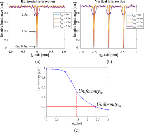
refers to the distance of the holographic image from the SLM plane,
, at which the value of
is 0.5. At
, the eye perceives the seam region of the reconstructed holographic image as starting to blur.
refers to the distance of holographic image from the SLM plane,
, at which the value of
is 0.2. At
, the eye does not perceive the seam of the reconstructed holographic image.
decreases drastically as
increases from 1 m to 3 m, as shown in Figure (c). When
is about 1.5 m, the value of
is 0.5, and when
is about 2.4 m, the value of
is 0.2. The seam of the holographic image is noticeable when
is less than 1.5 m. As
increases past 1.5 m, the seam area gradually vanishes. As
is more than about 2.4 m, the seam is not perceived because of
. The numerical results in Figure (c) and (d) indicate that the definitions for
and
are reasonable. Therefore, in the proposed multi-vision system the seamless virtual reference plane has a minimum distance of 2.4 m and a seamless holographic 3D image is successfully generated beyond that distance.
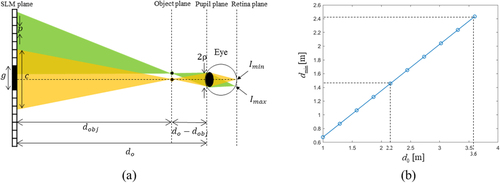
The threshold of a seamless virtual reference plane is calculated by using the of intensity contrast on the retina of an eye. If the wave field generated by the SLM reconstructs a point on the object plane and the eye focuses on that point, then the entire wave field by the SLM does not enter the eye, as shown in Figure (a). The pixel region that reconstructs the wave field entering the eye is called the circle of contribution and its diameter is given by
(8)
(8) Here,
is the radius of the pupil. In addition, the intensity of light diffracted by the pixels within the circle of contribution follows a distribution in the form of a
function, denoted by
. The circle of contribution has a circular shape, and a circular mask function to limit the region occupied by the circle of contribution is given by
(9)
(9) So, the maximum and minimum intensities at the retina are respectively given by
(10)
(10) and
(11)
(11) where
denotes the central value of the intensity profile diffracted from one pixel. The distance of the object point,
, that satisfies
in Equation (Equation7
(7)
(7) ) is called the minimum distance of seamless virtual reference plane,
. Since the viewing distance is extremely large compared to the size of the SLM, paraxial approximation is applicable. The minimum distance of seamless virtual reference plane is computed by
(12)
(12) where Figure (b) shows the relationship between the viewing distance,
, and the minimum distance of seamless virtual plane,
. In other words, if the viewing distance decreases by using a field lens with a small focal length, the minimum distance of seamless virtual plane also decreases. The required pixel pitch is obtained from Equation (Equation2
(2)
(2) ) because the viewing window size should remain the same even as the viewing distance decreases. A viewing window size of 28 mm is specified in our system. For a given pixel pitch of 57
, the viewing distance is 3.6 m and the minimum distance of the virtual reference plane is 2.4 m. If the pixel pitch is reduced to 34
, the viewing distance and the minimum distance of the virtual reference plane become 2.2 and 1.45 m, respectively.
Figure 7. (a) Optical geometry for the circle of contribution determined by a point at the object plane and (b) minimum distance of seamless virtual reference plane corresponding to the viewing distance when the size of viewing window is 28 mm.
To synthesize a full color CGH, a perfectly matched full color holographic field is initially set up on the retinal plane, and the optical field in the retinal plane is transmitted using the ICdFr algorithm to the SLM plane for the object space [Citation15, Citation18]. A depth-map CGH for each color is calculated independently by using ICdFr at the corresponding wavelength. The calculated light distribution fields in object space accumulate in the SLM plane to generate a full color composite hologram. Since no optical filter is used to remove unwanted noise in a direct view configuration, the CGH signal is placed off-axis in order to avoid DC noise. However, for full color CGHs, the signals for each color are distributed in different positions within the viewing zone according to the R/G/B wavelengths. DC noise is present on the optical axis in the viewing zone, while the hologram signal for the red wavelength is farthest from the optical axis and that for the blue wavelength is closest to the optical axis, thereby resulting in axial misalignment. In order to resolve this misalignment, it is necessary to independently calculate the R/G/B carrier waves to adjust the signal for each color in the same viewing zone.
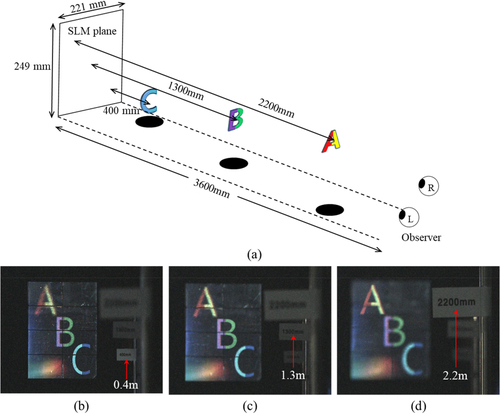
The experimental results for the proposed CGH synthesis algorithm for the generation of seamless full color holographic images are presented in Figure . The 3D objects are designed with full color letters of different depths. A, B, and C are located 2.2, 1.3, and 0.4 m in front of the SLM plane, respectively (Figure [a]). The experimental results in Figures (b), (c), and (d) demonstrate the holographic accommodation effect. When the observer focuses on C at a distance of 0.4 m from the SLM plane (Figure [b]), A and B are defocused. When the observer focuses on B at a distance of 1.3 m from the SLM plane (Figure [c]), A and C are defocused. Similarly, when the observer focuses on A at a distance of 2.2 m from the SLM plane (Figure [d]), B and C are blurred. When the observer looks at C, the seams are clearly visible, but when the observer looks at B, the seams are less apparent. In addition, the seams are barely noticeable when they look at A. In this experiment, when the distance between the object plane and the SLM plane is 2.2 m, the seam of the holographic image is barely discernible, and the measured value of uniformity is 0.23. Therefore, the experimental results show that the numerical analysis indicating that the minimum distance of the virtual reference plane is 2.4 m is valid. It is expected that the experimental result is slightly smaller than the numerical analysis result because the diffraction angle is wider based on the fill factor of the pixel. Furthermore, the diffracted light distribution is not symmetrical due to the asymmetric shape of the pixel.
Figure 8. Experimental results of the 3D objects with difference depth: (a) Design values of the objects, and experimental results focused on (b) C at a distance of 0.4 m, (c) B at a distance of 1.3 m, and (d) A at a distance of 2.2 m from the SLM.
4. Conclusion
In conclusion, we propose a holographic multi-vision display with a 16M pixel resolution made of eight (42) high-resolution transmission-type LCDs and investigate the seamlessness of the proposed architecture. A pixel structure in an asymmetric parallelogram generates a special diffraction pattern in the pupil plane. This pattern minimizes IPCT caused by a conventional symmetric pixel shape. The change of seam according to the distance of the object plane of the holographic image is theoretically analyzed, and a seamless virtual reference plane is defined in the multi-vision system. Optical experiments show that the proposed system successfully creates a full color seamless holographic 3D image on the virtual reference display plane and achieves the essential optical characteristics for a holographic display, including the accommodation effect and binocular parallax. The findings are consistent with the supportive numerical simulation results. A seamless holographic image is reconstructed at 2.4 m or more from the multi-vision display in the proposed holographic multi-vision system. Therefore, it is possible to provide a natural, seamless virtual scene at a distance of less than 1 m from the observer. In the current system, the backlight part of the multi-vision, such as the light source and the beam shaping part, becomes very bulky when using a reflective optical system. In the future, we plan to incorporate a waveguide, an optical component that uses total internal reflection to fold an optical path, into this system so as to make the system compact by reducing the illumination distance.
Disclosure statement
No potential conflict of interest was reported by the author(s).
Additional information
Funding
Notes on contributors

Woonchan Moon
Woonchan Moon received his B.S. and M.S. degrees from the School of Electronic and Electrical Engineering, Kyungpook National University, Daegu, Republic of Korea in 2014 and 2016, respectively, and he was a research engineer at LG Display for 5 years. He is currently studying for his Ph.D. degree at Kyungpook National University. His research focuses on 3D display, AR HUD, and holographic display.

Hosung Jeon
Hosung Jeon received his B.S. and M.S. degrees from the School of Electronic and Electrical Engineering, Kyungpook National University, Daegu, Republic of Korea in 2016 and 2021, respectively, and he is currently studying for his Ph.D. degree at Kyungpook National University. His research focuses on 3D display, AR/VR display, and holography applications.
Sungjae Park
Sungjae Park received his B.S. and M.S. degrees from the School of Electronics Information Engineering, Korea University, Sejong, Republic of Korea in 2016 and 2018, respectively, and he is currently studying for his Ph.D. degree at Korea University. His research focuses on holographic 3D displays, full color holography, and diffractive optical field simulation.

Soobin Kim
Soobin Kim received his B.S. and M.S. degrees from the School of Electronics Information Engineering, Korea University, Sejong, Republic of Korea in 2015 and 2018, respectively, and he is currently studying for his Ph.D. degree from Korea University. His research focuses on digital holography based on wave optics, especially diffractive optics for holographic display system.

Hwi Kim
Hwi Kim received his Ph.D. degree in 2007 from the School of Electrical Engineering, Seoul National University, Republic of Korea. In 2010, he joined the Department of Electronics and Information Engineering, Korea University, Sejong, Republic of Korea, where he is now a professor. He has authored or co-authored more than 120 journal papers in the field of diffractive optical field simulation for nano-structures and holographic devices.

Joonku Hahn
Joonku Hahn received the Ph.D. degree in 2009 from the School of Electrical Engineering, Seoul National University, Republic of Korea. In 2011, he joined the Faculty of Electronics Engineering, Kyungpook National University, Daegu, Republic of Korea, and he is now a professor. His main interests are 3D displays and digital holography applications.
References
- J. Hong, Y. Kim, H.-J. Choi, J. Hahn, J.-H. Park, H. Kim, S. Min, N. Chen, and B. Lee, Applied Optics 50 (34), H87–H115 (2011).
- D. Mendlovic, and A.W. Lohmann, Journal of the Optical Society of America A 14 (3), 558–562 (1997).
- N. Fukaya, K. Maeno, O. Nishikawa, K. Matsumoto, K. Sato, and T. Honda, Proc. SPIE 2406, 283–289 (1995).
- K. Maeno, N. Fukaya, O. Nishikawa, K. Sato, and T. Honda, Proc. SPIE 2652, 15–23 (1996).
- J. Hahn, H. Kim, Y. Lim, G. Park, and B. Lee, Optics Express 16 (16), 12372–12386 (2008).
- T. Kozacki, M. Kujawińska, G. Finke, B. Hennelly, and N. Pandey, Applied Optics 51 (11), 1771–1780 (2012).
- H. Sasaki, K. Yamamoto, Y. Ichihashi, and T. Senoh, Scientific Reports 4, 4000 (2014).
- H. Sasaki, K. Yamamoto, K. Wakunami, Y. Ichihashi, R. Oi, and T. Senoh, Scientific Reports 4, 6177 (2015).
- S. Lee, J. Moon, S. Yang, J. Rhim, B. Kim, Y. Lee, S. Han, S. Yoon, and I. Kang, SID Symposium Digest of Technical Papers 48 (1), 612–614 (2017).
- S. Lee, S. Lee, H. Yoon, C.-K. Lee, C. Yoo, J. Park, J. Byun, G. Kim, B. Lee, B. Lee, and Y. Hong, Optics Express 26 (2), 824–834 (2018).
- Y. Su, X. Tang, Z. Cai, J. Wu, Y. Chen, M. Hua, and W. Wan, Optics and Lasers in Engineering 129, 106079 (2020).
- N.-N. Li, D. Wang, C. Liu, S.-F. Lin, and Q.-H. Wang, Opt. Commun 453 (6), 123411 (2019).
- M. Park, B. Chae, H. Kim, J. Hahn, H. Kim, C. Park, K. Moon, and J. Kim, ETRI Journal 36 (2), 232–241 (2014).
- H. Kim, J. Kwon, and J. Hahn, Optics Express 26 (13), 16853–16874 (2018).
- J. Roh, K. Kim, E. Moon, S. Kim, B. Yang, J. Hahn, and H. Kim, Optics Express 25 (13), 14774–14782 (2017).
- D. Im, E. Moon, Y. Park, D. Lee, J. Hahn, and H. Kim, Optics Letters 39 (12), 3642–3645 (2014).
- J. An, G. Sung, S. Kim, H. Song, J. Seo, H. Kim, W. Seo, C.-S. Choi, E. Moon, H. Kim, H.-S. Lee, and U. Chung, SID Symposium Digest of Technical Papers 46 (1), 522–525 (2015).
- S. Park, J. Lee, S. Lim, M. Kim, S. Ahn, S. Hwang, S. Jeon, J. Jeong, J. Hahn, and H. Kim, Optics Express 29 (17), 26793–26807 (2021).
Appendix: Cascaded Fresnel Transform
We provide the mathematical formulation of the forward and backward cascaded Fresnel transforms. As shown in Figure , the schematic of the binocular holographic multi-vision display illustrates that the binocular CGH on the SLM plane generates wave field on the left eye retina plane and wave field on the right eye retina plane
.
and
are given, respectively, by.
(S1)
(S1)
(S2)
(S2) where
is the Fresnel forward propagation of optical field
by distance
,
is the transmittance function of the eye lens,
and
are the carrier wave terms for the left and right views, respectively,
and
are the left-view CGH and the right-view CGH, respectively, and
and
are represented as
(S3)
(S3)
(S4)
(S4) where
is the distance between the SLM plane
and the pupil plane
,
is the distance between the pupil plane
and the retina plane
,
is the interval between the left and right light sources,
is the inter-pupil distance,
is the circular function that represents the pupil, and
is the pupil radius. The focal length of the eye lens (
) is given by
(S5)
(S5) where
is the distance between the SLM plane and the object plane. For
and
, the inverse cascaded Fresnel transform produces
and
as
(S6)
(S6)
(S7)
(S7) where
represents the Fresnel backward propagation by distance,
. They are expressed mathematically as
(S8)
(S8)
(S9)
(S9)