
Abstract
We demonstrate using a diffractive smart window with homogeneous-aligned (HA) liquid crystals (LCs) owing to the large spatial phase difference in all directions in the opaque state. The proposed grating cell had a high haze value (88.57%), which was 1.16 times higher than the previously reported vertically aligned (VA) grating cells because the proposed grating cell had a higher twist angle than what the VA grating cell had. Our proposed HA grating cell can be used in various smart window applications.
Introduction
Smart or electronic window display technology has received a lot of interest lately since it allows the transmission of information through different media, converting windows into next-generation display devices. The transmittance and viewing angle in the transparent state, the haze value in the translucent state, power consumption, and switching time are some of the important factors that affect how well a window display screen performs. Because of their tunable optical properties, liquid crystal (LC) materials are frequently used in various photonic and display applications [Citation1–3]. However, due to the corresponding decrease in transmittance, implementing window displays crossing polarizers has become more challenging than normal LC display technologies. Hence, window display applications are better suited to LC technologies based on light scattering without using polarizers, such as polymer-stabilized liquid crystals (PSLCs), polymer-dispersed liquid crystals (PDLCs), and cholesteric liquid crystals (ChLCs), which have undergone extensive research [Citation4–14].
Light scattering is caused by the random orientation of LC molecules in polymer networks or droplets to achieve a translucent state with a high haze value in light shutters that use LC/polymer composites, such as PSLCs and PDLCs [Citation4–12]. However, due to the refractive index mismatch between the LC and polymer matrices, these devices have limited transmittance and a narrow viewing angle in the transparent state. They also require an operating voltage higher than 40 V. Additionally, ChLC devices have a delayed response time that is often greater than a few tens of milliseconds, an operating voltage higher than 35 V, and a complex drive scheme [Citation13,Citation14]. These characteristics make it challenging to use them as window displays.
Therefore, LC grating device has been widely researched for smart windows [Citation15–22]. It has various advantages, such as low operating voltage, fast response time, and a broad viewing angle in the transparent state. One of the methods for inducing diffraction is using a one-dimensional (1-D) LC grating cell [Citation17,Citation18]. It has a significantly fast response time, low operating voltage, and easy fabrication. However, the application is limited because it has a low haze value (51.2%) to actually use. Another method is the two-dimensional LC grating cell, consisting of top and bottom substrates with crossed interdigitated electrodes, which has been reported to overcome the drawbacks of a 1-D LC grating cell. It has a considerably high haze value (83.8%) [Citation19,Citation20]. However, the 2-D grating cell has drawbacks that delay turn-off response time and high operating voltage. In addition, there is a problematic fabrication owing to the difficulty of aligning the top and bottom interdigitated electrodes.
Here, we demonstrate a diffractive smart window using homogeneous-aligned (HA) LCs. Since electrodes crossing vertically and horizontally were used on only the bottom substrate, it induces a 2-D effect and makes fabrication easy. The proposed device can switch from a transparent to an opaque state by the applied voltage. The proposed grating cell has favorable characteristics, such as a high haze value (88.57%), low driving voltage (7.50 V), and fast response time, where the turn-on is 13.53 ms, and the turn-off is 16.41 ms (Figure S1). Therefore, the proposed cell can be applied to augmented reality (AR) and virtual reality (VR) devices, and variable smart window devices that require a high haze value and fast response time.
Operating principle
We used the commercial modeling tool TechWiz liquid-crystal display (LCD) 3D to simulate the electro-optical properties of a liquid crystal (LC) grating cell (Sanayi System Co., Ltd., Korea). A schematic illustrating the operation of the proposed HA grating cell is shown in Figure (a). The initially aligned LC molecules were rotated along the electric field directions using a patterned waffle-shaped electrode, inducing a significant spatial phase difference along the vertical and horizontal directions (Figure (b)). The proposed HA grating cell could also be turned opaque because of the diffraction effect caused by the considerable spatial phase difference. The virtual wall where the LCs are not oriented is indicated by the dotted black lines in Figure (b).
Figure 1. Proposed HA grating cell. (a) Operating schematic of the proposed HA grating cell. (b) Top view of LC director configurations. Calculated LC director distributions and phase difference profiles in (c) x, (d) y, and (e) diagonal directions.
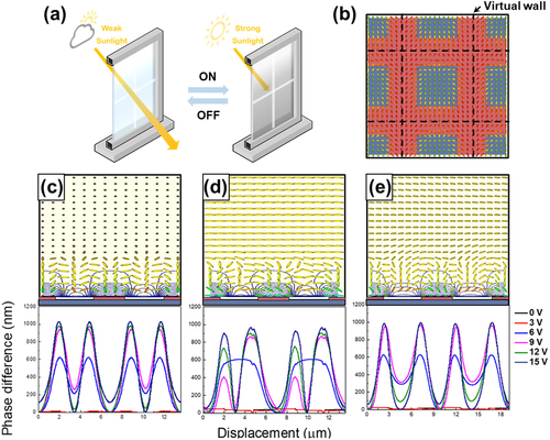
Figure (c)–(e) show the calculated director distributions in the LCs and phase difference profiles in the vertical, horizontal, and diagonal directions (applied voltage of 15 V). The waffle-shaped electrode was produced at the bottom substrate; the proposed cell exhibited a significant spatial phase difference in the vertical, horizontal, and diagonal directions. The waffle-shaped electrode reoriented more LC molecules along the direction of the applied electric field, causing the proposed cell to exhibit the same spatial phase difference along the diagonal direction that was exhibited along the vertical or horizontal directions, as shown in Figures (c)–(e). Regardless of the azimuthal angle, the proposed grating cell created a significant spatial phase difference when an electric field was applied; when white light entered the cell, it was diffracted and converted to an opaque state, owing to a significant spatial phase difference.
Results and discussion
The proposed HA grating cell was designed with horizontal alignment; a nematic LC (such as E7, Merck) with positive dielectric anisotropy (dielectric anisotropy Δε = 13.8, refractive indices no = 1.52 and ne = 1.75, elastic constants k11, k22, and k33 are 10.3, 7.4, and 16.5 pN, respectively); and a waffle-shaped electrode at the bottom substrate to achieve the study’s goals. The width, length, and cell gap of the patterned electrodes were 2.8, 4, and 20 µm, respectively. The pretilt angle, azimuthal angle, and wavelength of the TechWiz LCD 3D were set to 5°, 90°, and 543.5 nm, respectively. The far-field intensity was detected using a photodiode placed 30 cm from the LC cell with a maximum diffraction angle of 30°. We used an optical analysis method with a 2 × 2 extended Jones matrix and the Fraunhofer diffraction equation to model the diffraction.
As the applied voltage increased, we evaluated diffraction efficiencies of each order to calculate the electro-optic performance of the proposed HA grating cell, as shown in Figure (a). We calculated the first-order and second-order diffraction efficiencies by adding the intensity of the part marked with white dots shown in Figure (b). The diffraction efficiencies of the higher orders, which were lower than those of the zeroth-, first-, and second-orders, are not shown here.
Figure 2. Calculated (a) voltage-dependent diffraction efficiency and (b) condition for each diffraction order. (c) Polarized optical microscopy (POM) images of the proposed device with crossed polarizers and full-wave plate. (d) Diffraction pattern of the proposed device at different applied voltages from 0 to 12 V.
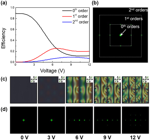
The polarized optical microscopy (POM) images of the proposed device with crossed polarizers at various applied voltages are shown in Figure (c). A full-wave plate (45°) was inserted between the crossed polarizers to determine the rotational direction of the LCs. The spatial phase difference resulting from the brightness (retardation) of most regions increased as the voltage increased, whereas the brightness (retardation) of the virtual wall remained constant. The created defect patterns functioned effectively as 2D diffraction gratings owing to the spontaneous fluctuation in the phase difference. When an unpolarized laser beam (543.5 nm) passed through the LC cell, green diffraction patterns were observed on the black screen (Figure [d]). Regardless of the polarization direction, the intensity of the zeroth-order diffraction energy was significantly reduced because most of the laser energy was focused on the higher orders. We observed that independent of the polarization direction, the diffraction energy was effectively transmitted from the zeroth- to higher-orders. We expected the proposed grating cell with the waffle-shaped electrode to switch to an opaque state independent of the azimuth angle because of the significant spatial phase difference.
We introduced total, specular, and diffuse transmittances and haze to evaluate the optical performance. The specular [diffuse] transmittance Ts [Td] refers to the ratio of the power of the beam that emerges from a sample cell – which is parallel (within a small range of angles of 2.5°) [not parallel] to the beam entering the cell – to the power carried by the beam entering the sample. The sum of the diffuse transmittance Td and specular transmittance Ts is the total transmittance Tt, and haze is calculated according to H = Td/Tt. The specular transmittance was obtained in our calculation by integrating the intensity over a range of 2.5° while Td was determined by subtracting Ts from Tt (Figure S2).
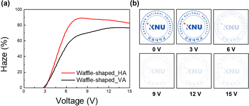
We validated the optical performance of the proposed device through comparison with the optical performance of a previously studied vertical alignment (VA) grating cell [Citation22]. The maximum haze value under the HA grating cell was 88.57% at 9 V, and the VA grating cell was 76.66% at 15 V, as shown in Figure (a). The HA grating cells accounted for approximately 1.16 times higher haze values than those under the VA grating cells. The proposed cell did not have any polymer matrices; the haze in the opaque state was caused by the electric-field-induced periodic continuous LC profile diffraction of the white incident light. Therefore, the proposed cell has several advantages over other LC cells, including low angle dependence, high stability, low operating voltage, and easy manufacturability. We simulated images of the LC grating cells placed on top of the Kangwon National University (KNU) logo at applied voltages ranging from 0 to 15 V, as shown in Figure (b).
Figure 3. (a) Haze values of the proposed device and (b) calculated transparent and opaque state images with the Kangwon National University (KNU) logo from 0 to 15 V.
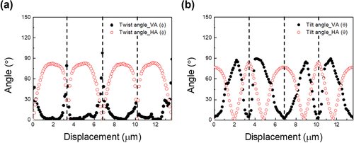
To understand the high haze value of the HA grating cell, we calculated the twist and tilt angles of the HA and VA cells at an applied voltage of 15 V, where the twist angle showed a remarkable difference between the HA and VA grating cells. Since the initial alignment of LCs was different (horizontal and vertical), the direction they reacted to in the electric field was also different. However, although the rotation position of the tilt angle was different, the LCs rotated at almost the same angle. Initially, the tilt angle was 5°; both the twist and tilt angles can have a high value. Additionally, at 15 V, the maximum phase difference of the HA grating cell (Figure [c]–[e]) was 1182.33 nm, which was approximately 3.42 times than the VA grating cell (Figure S3), 345.83 nm. These results could explain the haze characteristics, and it was confirmed that the HA grating cells were more suitable for smart window application than the VA grating cells were (Figure ).
Figure 4. Calculated angles of HA and VA grating cells at 15 V. (a) Twist and (b) tilt angles (vertical dotted lines represent the position of the virtual wall).
Conclusion
We demonstrate the electro-optical characteristics of an HA grating cell with a waffle-shaped electrode in the only bottom substrate for window display applications. It can be switched between the transparent and opaque states by applying an electric field. The proposed grating cell shows a high haze value (88.57%) owing to the large spatial phase difference from all directions. In addition, high fabricability by using only the bottom substrate, low power consumption, and easy driving. Therefore, the proposed HA grating cell could be a potential candidate for smart window applications.
Supplemental Material
Download MS Word (150.9 KB)Disclosure statement
No potential conflict of interest was reported by the author(s).
Data availability
Data underlying the results presented in this paper are not publicly available at this time but may be obtained from the authors upon reasonable request.
Additional information
Funding
Notes on contributors

Chan-Hee Han
Chan-Hee Han obtained his B.S. degree in Electrical Information Communication Engineering from Kangwon National University (KNU) in Samcheok, Republic of Korea, in 2022. He is currently a master’s degree student at KNU. His research interests include diffractive liquid crystal devices, augmented reality, and self-shading windows for energy saving.

Tae-Hoon Choi
Tae-Hoon Choi received his B.S. degree in Electronics Engineering from Pusan National University in 2013 and his M.S. and Ph.D. degrees at the same institute in 2015 and 2019, respectively. He is currently a research engineer at the Korea Automotive Technology Institute.

Wook-Sung Kim
Wook-Sung Kim obtained his B.S. and M.Sc. (Physics) from Korea University, the Republic of Korea, in 1989 and 1991 respectively, and his Ph.D. (Engineering Science) from the University of Oxford in 2010. He was a research engineer at LG Display for 26 years and is currently an associate professor at Pohang University of Science and Technology (POSTECH) in Pohang, Korea. His research interests include traditional displays, near-eye displays for AR and VR, and future displays. He also has research activities related to wave array technologies, such as LC-based antennas, metasurface applications, and ultrasound arrays for various applications.

Seung-Won Oh
Seung-Won Oh received his B.S. and Ph.D. degrees in electronics engineering from Pusan National University in 2013 and 2018, respectively. From 2019 to 2020, he was a postdoctoral researcher at Liquid Crystal Institute, Kent State University, OH, USA. From 2020 to 2021, he was a postdoctoral researcher at the Wave Array and Display Engineering (WADE) Laboratory of Pohang University of Science and Technology. He is currently an associate professor at Kangwon National University. His research interests include self-shading windows for energy saving, liquid crystal cells for photonics, liquid crystal elastomers, and antennas with liquid crystals.
References
- G. Sun, X. Cao, H. Zhou, S. Bao, and P. Jin, A novel multifunctional thermochromic structure with skin comfort design for smart window application, Sol. Energy Mater Sol. Cells. 159, 553–559 (2017).
- J.-S. Ma, J.-Y. Choi, S.-W. Oh, and W.-S. Kim, Liquid-crystal-based floating-electrode-free coplanar waveguide phase shifter with an additional liquid-crystal layer for 28-GHz applications, J. Phys. D: Appl. Phys. 55, 095106 (2022).
- C.H. Han, Y. Choi, S.W. Oh, and T.H. Yoon, Asymmetrically anchored liquid crystal cell for display and photonics applications, Liq. Crys. 1-9 (2022).
- R.A.M. Hikmet, Electrically induced light scattering from anisotropic gels, J. Appl. Phys. 68 (9), 4406–4412 (1990).
- H. Ren, Y.H. Lin, Y.H. Fan, and S.T. Wu, In-plane switching liquid crystal gel for polarization-independent light switch, J. Appl. Phys. 96, 3609–3611 (2004).
- J. Heo, J.-W. Huh, and T.-H. Yoon, Fast-switching initially-transparent liquid crystal light shutter with crossed patterned electrodes, AIP Adv. 5 (4), 047118 (2015).
- J.W. Doane, N.A. Vaz, B.G. Wu, and S. Zumer, Field controlled light scattering from nematic microdroplets, Appl. Phys. Lett. 48 (4), 269–271 (1986).
- J.A. Sofi, and D. Surajit, Stability of liquid crystal micro-droplets based optical microresonators, Liq. Cryst. 46 (4), 629–639 (2019).
- P.P. Crooker, and D.K. Yang, Polymer-dispersed chiral liquid crystal color display, Appl. Phys. Lett. 57 (24), 2529–2531 (1990).
- S.-W. Oh, J.-M. Baek, J. Heo, and T.-H. Yoon, Dye-doped cholesteric liquid crystal light shutter with a polymer-dispersed liquid crystal film, Dyes Pigm. 134, 36–40 (2016).
- Y.-G. Choi, S.-W. Oh, T.-H. Choi, B.-H. Yu, and T.-H. Yoon, Formation of polymer structure by thermally-induced phase separation for a dye-doped liquid crystal light shutter, Dye Pigm. 163, 749–753 (2019).
- J.-H. Lee, J.-J. Lee, Y.-J. Lim, S. Kundu, S.-W. Kang, and S.-H. Lee, Enhanced contrast ratio and viewing angle of polymer-stabilized liquid crystal via refractive index matching between liquid crystal and polymer network, Opt. Express 21 (22), 26914–26920 (2013).
- D-K Yang, L.-C. Chien, and J.-W. Doane, Cholesteric liquid crystal/polymer dispersion for haze-free light shutters, Appl. Phys. Lett. 60 (25), 3102–3104 (1992).
- D.K. Yang, J.L. West, L.C. Chien, and J.W. Doane, Control of reflectivity and bistability in displays using cholesteric liquid crystals, J. Appl. Phys. 76 (2), 1331–1333 (1994).
- C.V. Brown, E.E. Kriezis, and S.J. Elston, Optical diffraction from a liquid crystal phase grating, J. Appl. Phys. 91 (6), 3495–3500 (2002).
- H. Chen, G. Tan, Y. Huang, Y. Weng, T.-H. Choi, T.-H. Yoon, and S.T. Wu, A low voltage liquid crystal phase grating with switchable diffraction angles, Sci. Rep. 7 (1), 39923 (2017).
- T.-H. Choi, J.-H. Woo, J.-M. Baek, Y. Choi, and T.-H. Yoon, Fast control of haze value using electrically switchable diffraction in a fringe-field switching liquid crystal device, IEEE Trans. Electron. Devices 64 (8), 3213–3218 (2017).
- H. Chen, G. Tan, Y. Huang, Y. Weng, T.-H. Choi, T.-H. Yoon, and S.-T. Wu, A low voltage liquid crystal phase grating with switchable diffraction angles, Sci. Rep. 7 (1), 1–8 (2017).
- T.-H. Choi, J.-W. Huh, J.-H. Woo, J.-H. Kim, Y.-S. Jo, and T.-H. Yoon, Switching between transparent and translucent states of a two-dimensional liquid crystal phase grating device with crossed interdigitated electrodes, Opt. Express 25 (10), 11275–11282 (2017).
- T.-H. Choi, J.-H. Woo, B.-G. Jeon, J. Kim, M. Cha, and T.-H. Yoon, Fast fringe-field switching of vertically aligned liquid crystals between high-haze translucent and haze-free transparent states, Liq. Cryst. 45 (10), 1419–1427 (2018).
- S.-W. Oh, B.-G. Jeon, T.-H. Choi, S.-M. Do, and T.-H. Yoon, Independent control of haze and total transmittance with a dye-doped liquid crystal phase-grating device, Appl. Opt. 58, 4315–4319 (2019).
- C.-H. Han, H. Eo, T.-H. Choi, W.-S. Kim, and S.-W. Oh, A simulation of diffractive liquid crystal smart window for privacy application, Sci. Rep. 12 (1), 1–7 (2022).