
 ?Mathematical formulae have been encoded as MathML and are displayed in this HTML version using MathJax in order to improve their display. Uncheck the box to turn MathJax off. This feature requires Javascript. Click on a formula to zoom.
Abstract
To integrate excellent heat dissipation and electromagnetic interference (EMI) shielding properties, some flexible hybrid sheets were fabricated using a polydimethylsiloxane (PMDS) matrix for a foldable display. The PDMS matrix was filled with Cu flakes and silicon carbide (SiC) powder, known for its high thermal conductivity and excellent EMI shielding properties, improving heat dissipation and EMI shielding. The acrylate resin used for an adhesive had Graphene powder and hexagonal-boron nitride (h-BN) as fillers with high heat dissipation characteristics. The optical microscopy confirmed multiple heat-transfer paths formed by the fillers. In the fabricated foldable hybrid sheet, the in-plane and out-of-plane thermal conductivities were 0.81 and 0.61
, respectively. EMI shielding rate was 11.67
(X Band, 8∼12
). In addition, the hybrid sheet exhibited excellent flexibility without microcracks in 2R repeated bending tests over 300,000 cycles.
1. Introduction
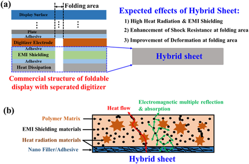
In electrical and electronic devices and automotive applications, displays are increasingly in demand to meet customers’ needs for lightweight design, compactness, and high-performance application processors (APs), leading to a growing demand for enhanced heat dissipation and electromagnetic interference (EMI) shielding performance [Citation1,Citation2]. Moreover, various problems arise due to heat and electromagnetic waves generated in the limited space of the device. The generated heat impairs the functionality of the components and causes malfunctions in neighboring components and substrate degradation [Citation3,Citation4]. In addition, electromagnetic waves pose harmful effects on the human body [Citation5,Citation6] and lead to malfunction and signal quality degradation in electronic devices due to electromagnetic interference (EMI) [Citation7,Citation8]. To address these complex problems, coating or attaching the films with materials possessing excellent thermal conductivity and EMI shielding properties is commonly adopted for products prone to heat generation [Citation9,Citation10]. Among the materials attracting attention as heat dissipation materials, polymer composite materials with high thermal conductivity by adding fillers are attracting attention [Citation11,Citation12]. Graphene [Citation13,Citation14], h-BN (hexagonal-Boron Nitride) [Citation15,Citation16], metal particles [Citation17,Citation18], and ceramics [Citation19,Citation20] are mainly used as high thermal conductivity fillers, among which graphene and h-BN particles in the carbon base materials exhibit excellent heat conductivity and heat stability, making them suitable materials for heat dissipation applications. Fillers with excellent heat dissipation properties are commonly added into a flexible PMDS matrix to enhance heat dissipation characteristics and enable foldable properties. PDMS, a silicone-based rubber, is highly deformable by external forces but has high resilience and excellent electrical insulation and chemical resistance [Citation21,Citation22]. When manufacturing a high thermal conductivity filler/PDMS composite material, optimizing the size and mixing ratio of the high thermal conductivity filler is necessary because it forms a thermal path within the composite and is significant in determining thermal conductivity. In addition, high thermal conductivity fillers generally have excellent electrical conductivity. Hence, they can be used for EMI shielding. Thus, to effectively implement an EMI shield, considering the shielding material’s electrical characteristics (e.g. electrical conductivity, magnetic permeability, permittivity) is essential. When encountering different materials along its incident path, electromagnetic waves are partially reflected, partially absorbed, or undergo multiple reflections depending on the material’s electrical properties. At the same time, the remainder passes through the material [Citation23,Citation24]. Typically, carbon-based materials such as graphene and carbon nanotubes (CNTs) are utilized as fillers for electromagnetic wave absorbers within polymer matrices due to their high electrical conductivity relative to their low weight. However, since general EMI shielding and heat dissipation sheets are rigid, high-modulus materials, existing heat dissipation, and EMI shielding sheets are unsuitable for foldable displays requiring bending characteristics of 2R or less. In addition, in the case of a foldable display, since the bending stiffness of the foldable display module is a concentrated folding area [Citation25,Citation26], the metal or polymer material’s plate metal supporting the display module is patterned with a special structure, which can reduce the folding area’s bending stiffness. In particular, when a digitizer is used with a digital pen, heat dissipation film, and EMI shielding sheet, the folding area is cut into two parts to reduce the display module’s bending stiffness (Galaxy Fold3 standard). As shown in Figure , if there is a space in the folding area, it is vulnerable to heat dissipation and EMI shielding, and it may be weak to shock resistance and bending deformation. To solve these disadvantages, this research prepared a foldable hybrid sheet with excellent heat dissipation and EMI shielding and flexibility. The proposed hybrid sheet prepared in this study is divided into two layers: a nanofiller/PDMS layer for heat dissipation and EMI shielding, and a nanofiller/acrylate layer for adhesion. Furthermore, nanofiller/PDMS composites used Cu flakes (∼80 wt) and SiC powder (∼10 wt
) as fillers. The nanofiller/acrylate resin used graphene powder (∼10 wt
) and h-BN powder (∼10 wt
) as fillers. In one of the previously published studies, a composite of PDMS/CNT (2wt
)/Zinc Oxide (5wt
) [Citation27] exhibited an EMI shielding effectiveness (SE) ranging from 10 dB to 15 dB, similar to the SE of 11.67 obtained in our study. However, despite the individual MWCNTs having an exceptionally low electrical resistance of 5.1
, their EMI SE was not particularly high. In contrast, the results achieved using Cu flakes in our study were considered significant, considering the material cost and ease of fabrication. Similarly, in [Citation28], PDMS/carbon fiber composites (5wt
) achieved a thermal conductivity of approximately 0.7
, which is lower than the current study’s result, which recorded 0.81
. The fabricated hybrid sheet is characterized through thermal conductivity measurement, EMI shielding analysis, and banding test.
Figure 1. Schematic diagram of the effects and structure of the hybrid sheet for foldable displays: (a) effects of the foldable hybrid sheet research and (b) structure of the foldable hybrid sheet.
2. Experimental section
2.1. Materials
The polydimethylsiloxane (PDMS) used in this study was obtained from Japan Shin-Etsu Chemical Co., Ltd (product code: KE-1243). Cu flake, silicon carbide, and hexagonal-boron nitride were purchased from Sigma-Aldrich and used as received. The Cu flake is approximately 75 , the silicon carbide is approximately 100
, and the hexagonal-boron nitride is approximately 500
. The 20
multilayer graphene (MLG) was obtained from Sphere Sciences (product code: ML-0420).
2.2. Manufacturing method of the all-in-one hybrid sheet for foldable display
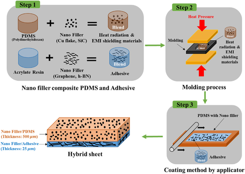
Figure illustrates the fabrication schematic of the foldable hybrid sheet. In Step 1, PDMS and acrylic resin were blended with nanofillers. Then, the specially blended PDMS composite was degassed in a vacuum chamber for 10 min. In Step 2, the PDMS composite was fabricated using a 500 thick metal mold by thermal lamination at 150
–200
and a pressure of 10
pressure. In Step 3, an applicator coated the fabricated nanofiller/PDMS composite sheet with the nanofiller/acrylic resin composite blended in Step 1 to impart adhesion properties. Adjusting the applicator’s spacing, the adhesive layer’s thickness can be controlled between 12
to 50
. The acrylic resin was cured at 120°C for 80 s. After curing the adhesive layer, the foldable hybrid sheet was fabricated.
Figure 2. Schematic diagram of the fabrication of a foldable hybrid sheet.
3. Results and discussion
3.1. Thermal conductivity properties of the prepared hybrid sheet
Figure (a) displays the surface composed of 100 wt% acrylate. Figure (b)∼(e) show the surface with MLG powder added at 1, 3, 5, and 10 wt%, respectively, to the acrylate polymer. Similarly, Figure (f)∼(i) indicate the surface with h-BN powder added at 1, 3, 5, and 10 wt%, respectively, to the acrylate polymer. When the content of MLG powder increases from 1 wt to 10 wt%, the MLG particles excessively protrude from the surface, particularly beyond 3 wt
. These protruded MLG particles form additional thermal conduction paths enhanced the heat dissipation capability. However, using fillers with a content exceeding 10 wt
adversely affected the adhesive strength of the coating layer. Conversely, when the h-BN powder increased from 1 wt
to 10 wt
, no noticeable surface protrusion of the h-BN particles was observed, and the adhesive strength had not weakened. This is because MLG particles are approximately 20
, leading to excessive filling and micro-scale surface protrusions. In contrast, h-BN particles are approximately 500
, preventing significant micro-scale surface protrusions. However, using high filler concentrations exceeding 10 wt
should be avoided due to the significantly lower h-BN density compared to the acrylate resin’s density. Figure (b)∼(e) reveal the cross-section with Cu flakes added at 5, 35, 65, and 80 wt%, with each sample also including 1 wt% SiC. Similarly, Figure (f)∼(i) show the cross-section with SiC added at 3, 5, and 10 wt%, with each sample including 5 wt% Cu flakes. When the Cu flake content increased from 5 wt
to 80 wt
, it can be observed in Figure (c) that the Cu flake particles did not come close to 10 μm of each other for concentrations below 35 wt
. However, at a high concentration of 80 wt
, the Cu flake particles within the PDMS formed multiple heat-transfer paths by connecting within 10
of each other, as reflected in Figure (e). These results confirmed that a minimum filler content of 65 wt
is required to fill PDMS with Cu flake and form multiple heat-transfer paths. As for SiC powder, due to its density and approximately 300 times smaller size than the PDMS, it was used as a filler at a maximum content of 10 wt
. The Cu flake filler is vital in connecting within the PDMS and forming multiple heat-transfer paths. Simultaneously, the SiC powder, as a ceramic-based nano-scale particle, filled the micro gaps in the thermal conduction paths and functioned as an EMI shielding material capable of absorbing electromagnetic waves within the composite.
Figure 3. Surface optical image of the nanofiller/acrylate resin composite: (a) Reference, (b) Type A, (c) Type B, (d) Type C, (e) Type D, (f) Type E, (g) Type F, (h) Type G, (i) Type H.
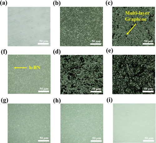
Figure 4. Cross-sectional optical image of the nanofiller/PDMS composite: (a) Reference, (b) Type A
, (c) Type B
, (d) Type C
, (e) Type D
, (f) Type E
, (g) Type F
, and (h) Type G
.
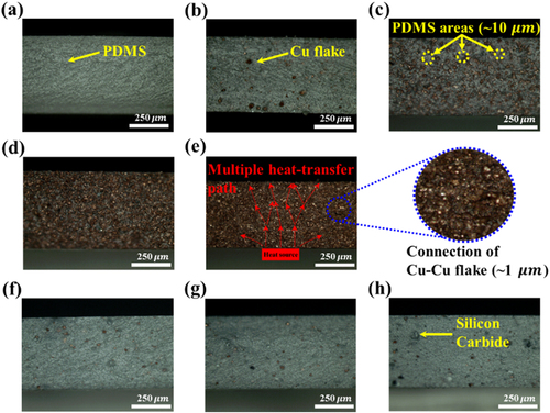
Figure details the correlation between thermal conductivity and adhesive strength of the MLG/acrylate adhesive layer. The MLG/acrylate adhesive layers of 25 , thickness coated on a 300 μm-thick Cu substrate for measurement. Thus, as the MLG content increased to a maximum of 10 wt%, the in-plane thermal conductivity increased by 25% compared to the reference, and the out-of-plane thermal conductivity increased by 70% compared to the reference. Conversely, the adhesion strength decreased by −81
compared to the reference as the thermal conductivity increased. This phenomenon can be attributed to graphene’s protrusion on the adhesive layer surface, which forms thermal conduction paths and enhances thermal conductivity but reduces adhesion strength. Adding less than 1 wt
MLG was necessary to maintain adhesion strength, although achieving significant improvement in thermal conductivity remained challenging. Figure demonstrates the correlation between thermal conductivity and adhesive strength of the h-BN/acrylate adhesive layer. The in-plane thermal conductivity of the h-BN/acrylate adhesive system increased by 25
compared to the reference as the h-BN content increased by a maximum of 10 wt
. In contrast, the out-of-plane thermal conductivity showed a 33
increase. On the other hand, as the h-BN content increased by 10 wt
, the adhesion strength increased by 71% compared to the reference. This can be due to the small particle size (∼500 nm) of h-BN, which increased elastic modulus through adsorption or entanglement with acrylate molecules [Citation29,Citation30]. Consequently, as the h-BN content increased, the adhesion strength was expected to increase. Therefore, using h-BN as a filler is beneficial when considering thermal conductivity and adhesion strength. Table summarizes the measurement results of thermal conductivity and adhesion strength for the nanofiller/acrylate adhesive.
Figure 5. The correlation between thermal conductivity and adhesion strength of the MLG/acrylate adhesive layer.
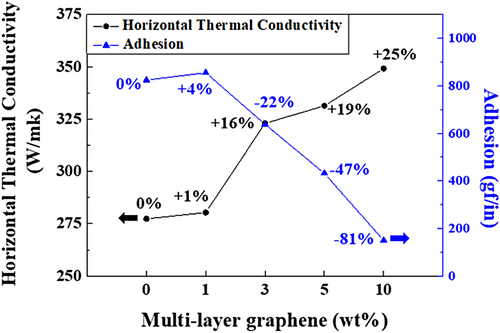
Figure 6. The correlation between thermal conductivity and adhesion strength of the h-BN/acrylate adhesive layer.
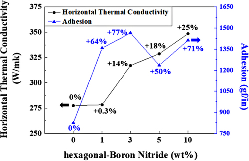
Table 1. Thermal conductivity and adhesion of nanofiller/acrylate adhesive layer.
3.2. EMI shielding properties of the prepared hybrid sheet
Figure differentiates the correlation between the content of Cu flake and the tensile strength of Cu flake/PDMS composites. As the Cu flake content increased by 80 wt, the shielding efficiency and tensile strength improved by 403
and 1319
, respectively, compared to the reference. This can be attributed to the increased elastic modulus of Cu flake due to adsorption or entanglement with PDMS molecules, improving the tensile strength [Citation29,Citation30]. Additionally, the conductive Cu flake enhances the electromagnetic wave shielding performance. [Citation31,Citation32]. When the Cu flake content was 80 wt
the shielding efficiency and tensile strength were measured as 11.67
and 12.7
, respectively. Moreover, it confirms that the shielding efficiency and tensile strength increased from the Cu flake content of 35 wt
or more. Figure shows the correlation between EMI shielding efficiency and tensile strength of the SiC/PDMS composite. The SiC powder content increased up to 10 wt
, and at that point, the EMI shielding efficiency and tensile strength were measured as 1.53
and 8.88
, respectively. Although SiC powder was expected to act as an absorber for electromagnetic waves in the PDMS matrix, it exhibited lower performance than the Cu flake fillers. This can be attributed to the density difference between PDMS and SiC, which limited the content to 10 wt
and hindered the practical improvement of EMI shielding efficiency and tensile strength. Hence, to achieve effective electromagnetic wave shielding, it can be assumed that SiC with particle sizes of ∼10
or larger or a foam-like structure [Citation33,Citation34] would be required to fill the fine gaps and contribute to heat diffusion. Table synthesizes the EMI shielding efficiency and tensile strength measurement results for the nanofiller/PDMS composite.
Figure 7. The correlation between EMI shielding and tensile strength of the Cu flake/PDMS composite.
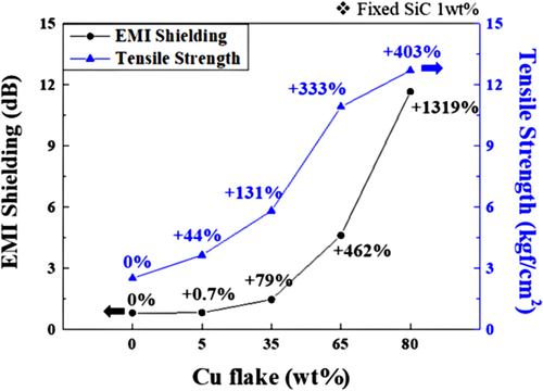
Figure 8. The correlation between EMI shielding and tensile strength of the SiC/PDMS composite.
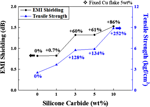
Table 2. EMI shielding efficiency, tensile strength, and Young's modulus of the nanofiller/PDMS composite.
3.3. Folding properties of the prepared hybrid sheet
Figure describes the tensile extension and a schematic of the 2R bending of the nanofiller/PDMS composite. In Figure (a), when the substrate was bent at 2R, the substrate was bent in a semicircle shape with a radius of 1R, where the outer diameter of the semicircle was calculated as 6.28 (2πR/2, at R = 2
). Figure (b) indicates the tensile test results of the hybrid sheet. In particular, within the extension range of 6.28
, the inserted graph demonstrates a linear increase of deformation to the applied load, indicating an elastic deformation behavior. Even if an external force deforms the object, it will return to its original shape when the force is removed. Therefore, the hybrid sheet shows the folding characteristics more than 300,000 times in 2R without substrate damage in 2R bending because the plastic deformation of the material does not occur despite the repeated folding and unfolding processes at the tensile section within 6.28 mm (Figure ). Meanwhile, the adhesive used, acrylate resin, is generally at room temperature and has a modulus of approximately several tens of
, so its impact on the foldable characteristics of the PDMS sheet coated with the adhesive is minimal. Thus, the fabricated hybrid sheet (Type B + Type D
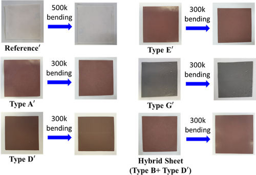
) exhibits folding characteristics capable of withstanding repeated folding and unfolding at 2R (Figure ).
Figure 9. Nanofiller/PDMS composite (a) schematic of 2R bending, (b) tensile-strength evaluation data.
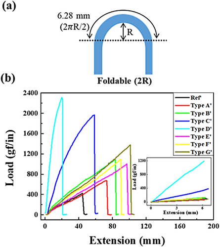
Figure 10. Before and after hybrid sheet 2R bending test results.
4. Conclusions
The foldable hybrid sheet was fabricated by incorporating nano-fillers into a PDMS matrix. The EMI shielding efficiency and tensile strength effectively increased with a content of Cu flake exceeding 35 wt within the PDMS matrix. Conversely, using SiC at a high content (>10 wt
) in PDMS composites is deemed inappropriate due to its very low density. Furthermore, the content of graphene and h-BN mixed with acrylate resin (adhesive) for imparting adhesion was determined valid up to a maximum of 10 wt
as higher contents can lead to reduced adhesion and scattering of particles on the surface, potentially causing shorts in electronic devices. The foldable hybrid sheet (Type B + Type D
) coated with adhesive on PDMS composite exhibited excellent flexibility without microcracks in the repeated bending test of 300,000 times at 2R. The in-plane and out-of-plane thermal conductivities were 0.81
and 0.61
, respectively, and the EMI shielding rate was 11.67
(X Band, 8∼12
). This foldable hybrid sheet exhibited excellent thermal dissipation and EMI shielding properties, improved the flexural deformation caused by repetitive bending in the folding region, enhancing its impact resistance. Hence, the foldable hybrid sheet is recommended to be applied to various electronic devices in semiconductors, electronics, and automotive industries.
Disclosure statement
No potential conflict of interest was reported by the author(s).
Additional information
Notes on contributors

Dong-Hoon Jang
Dong-Hoon Jang is a postdoctoral graduate from the Department of Display Engineering at Dankook University, Cheonan-si, Korea. He received his Ph.D. in Electronics and Electrical Engineering from Dankook University. His research interests include flexible display module process, self-healing polymer, surface analysis, and heat-radiating sheet.

Tae-Wan Kim
Tae-Wan Kim is a master's student at the Department of Electronics and Electrical Engineering at Dankook University, Jukjeon, Korea. He received a bachelor in Display Engineering from Dankook University. His research interests include flexible display module processes and heat-radiating sheets.

Young-Do Kim
Young-Do Kim is a researcher at Samsung Display in Yongin-si, South Korea. He received his Ph.D. in Materials Science and Engineering from Seoul National University. The research fields he is focused on are coloring materials and functional adhesives for flexible displays.

Kwan-Young Han
Kwan-Young Han is a professor at the Department of Display Engineering, Dankook University, Cheonan-si, Korea. He received his Ph.D. in electronics and flat panel display molecular orientation and control from the Tohoku University in Japan. He is interested in research on module development for flat panel displays, including OLED TFE processors and equipment for OLED modules.
References
- S.C. Kim, C.H. Kim, G.H. Yang, T.H. Yang, B.K. Han, S.C. Kang, and D.S. Kwon, IEEE, 69–74 (2009).
- D. Cheng, Y. Wang, H. Hua, and J. Sasian, Opt. Lett. 36 (11), 2098–2100 (2011).
- P.E. Burrows, V. Bulovic, S.R. Forrest, L.S. Sapochak, D.M. McCarty, and M.E. Thompson, Appl. Phys. Lett. 65 (23), 2922–2924 (1994).
- S. Chung, J.H. Lee, J. Jeong, J.J. Kim, and Y. Hong, Appl. Phys. Lett. 94 (25), 168 (2009).
- C.C. Johnson, and A.W. Guy, Proc. IEEE 60 (6), 692–718 (1972).
- J.C. Lin, IEEE Microwave Mag. 17 (6), 32–36 (2016).
- C.M. Belcastro, In Proceedings of the 1999 IEEE International Conference on Control Applications 2, 1531–1537 (1999).
- K. Murakawa, N. Hirasawa, H. Ito, and Y. Ogura, In 2014 International Symposium on Electromagnetic Compatibility, 581–584 (2014).
- L. Zou, C. Lan, S. Zhang, X. Zheng, Z. Xu, C. Li, L. Yang, F. Ruan, and S.C. Tan, Nano-Micro Lett. 13, 1–16 (2021).
- L.C. Jia, C.G. Zhou, W.J. Sun, L. Xu, D.X. Yan, and Z.M. Li, Chem. Eng. J. 384, 123368 (2020).
- M. Wang, X.H. Tang, J.H. Cai, H. Wu, J.B. Shen, and S.Y. Guo, Carbon 177, 377–402 (2021).
- D. Wanasinghe, F. Aslani, G. Ma, and D. Habibi, Nanomaterials 10 (3), 541 (2020).
- A.A. Balandin, S. Ghosh, W. Bao, I. Calizo, D. Teweldebrhan, F. Miao, and C.N. Lau, Nano Lett. 8 (3), 902–907 (2008).
- S. Chen, Q. Wu, C. Mishra, J. Kang, H. Zhang, K. Cho, W. Cai, A.A. Balandin, and R.S. Ruoff, Nat. Mater. 11 (3), 203–207 (2012).
- S.L. Chung, and J.S. Lin, Molecules 21 (5), 670 (2016).
- H. Shen, J. Guo, H. Wang, N. Zhao, and J. Xu, ACS Appl. Mater. Interfaces 7 (10), 5701–5708 (2015).
- Y.P. Mamunya, V.V. Davydenko, P. Pissis, and E.V. Lebedev, Eur. Polym. J. 38 (9), 1887–1897 (2002).
- S.P. Yuan, and P.X. Jiang, Int. J. Thermophys 27, 581–595 (2006).
- C.P. Wong, and R.S. Bollampally, J. Appl. Polym. Sci. 74 (14), 3396–3403 (1999).
- B.L. Zhu, J. Ma, J. Wu, K.C. Yung, and C.S. Xie, J. Appl. Polym. Sci. 118 (5), 2754–2764 (2010).
- D. Qi, K. Zhang, G. Tian, B. Jiang, and Y. Huang, Adv. Mater. 33 (6), 2003155 (2021).
- Z. Yang, W. Wang, L. Bi, L. Chen, G. Wang, G. Chen, C. Ye, and J. Pan, Nanoscale 12 (31), 16562–16569 (2020).
- M.H. Al-Saleh, and U. Sundararaj, Carbon 47 (7), 1738–1746 (2009).
- H. Wang, S. Li, M. Liu, J. Li, and X. Zhou, Macromol. Mater. Eng. 306 (6), 2100032 (2021).
- M.S. Bae, C. Park, D. Shin, S.M. Lee, and I. Yun, Solid-State Electron 133, 1–5 (2017).
- H.C. Cheng, W.H. Xu, W.H. Chen, P.H. Wang, K.F. Chen, and C.C. Chang, Adv. Mater. Sci. Eng. (2015).
- S. Panda, and B. Acharya, J. Mater. Sci.: Mater. Electron. 32 (12), 16215–16229 (2021).
- J. Wei, M. Liao, A. Ma, Y. Chen, Z. Duan, X. Hou, M. Li, N. Jiang, and J. Yu, Compos. Commun. 17, 141–146 (2020).
- G. Das, and S. Biswas, IOP Conf. Ser.: Mater. Sci. Eng. 115 (1), 012012 (2016).
- M. Sayer, Compos. Part B Eng. 59, 12–20 (2014).
- J.H. Byeon, and J.W. Kim, Thin Solid Films 520 (3), 1048–1052 (2011).
- M. Wang, X. You, C. Liao, X. Ren, F. Xiu, J. Yang, and S. Dong, Mater. Chem. Front. 6 (16), 2256–2265 (2022).
- C. Liang, Z. Wang, L. Wu, X. Zhang, H. Wang, and Z. Wang, ACS Appl. Mater. Interfaces 9 (35), 29950–29957 (2017).
- P. Wilson, S. Vijayan, and K. Prabhakaran, J Ind. Eng. Chem. 80, 401–410 (2019).