
 ?Mathematical formulae have been encoded as MathML and are displayed in this HTML version using MathJax in order to improve their display. Uncheck the box to turn MathJax off. This feature requires Javascript. Click on a formula to zoom.
Abstract
This paper attempts to explore the feasibility of using cholesteric liquid crystals (CLCs) for reflective displays in active matrix (AM) driving. The study focuses on reverse mode polymer-stabilized cholesteric liquid crystals (PSCLCs) to overcome the inherent bistability of CLCs and achieve faster response times for switching between bright and dark states. Key parameters such as cell gap, monomer concentration, polymerization temperature, and different monomer types and liquid crystal hosts are systematically investigated to optimize the electro-optical properties of the liquid crystals for active matrix driving. The research demonstrates that PSCLCs can operate within a 15 V driving voltage range while maintaining a good bright-dark state contrast ratio (>10) and a response time of less than 42 ms. This suggests significant potential for their application in dynamic reflective display technologies.
1. Introduction
Recently, reflective displays have gained widespread attention. In comparison to traditional transmissive displays (e.g. LCD, OLED, etc.) [Citation1, Citation2], the most significant difference of reflective displays lies in their ability to achieve display effects without the need for a backlight module or inherently emissive materials. By utilizing ambient light reflection, information can be conveyed to the eyes, such as on paper, paintings, or advertising billboards. The material itself can also change displayed information by applying energy. In addition to advantages such as eye protection and energy efficiency, the crucial benefit is the enhanced readability in outdoor or brightly lit environments.
Reflective displays can be divided into two categories: bistable and non-bistable. Bistable displays can maintain image visibility without continuous power supply, demonstrating energy-efficient characteristics. Their applications are prominent in static-image scenarios, such as e-paper, advertising billboards, and price tags. The mainstream technology for bistable reflective displays is electronic ink (e-ink) [Citation3–6]. Recently, cholesteric liquid crystal [Citation7–10] technology has emerged as a potential player, expanding the application scope of reflective displays due to its better color performance and temperature stability. Non-bistable reflective displays can be achieved using reflective mode TN, MTN LCDs by removing the backlight module [Citation10–12]. This technology builds upon mature display techniques, ensuring simplicity, reliability, and, importantly, the ability to display high frame-rate content. However, when combined with polarizers, color filters, and matrix driving, the reflective efficiency is significantly restricted, leading to suboptimal display quality. Therefore, utilizing cholesteric liquid crystal technology to create non-bistable reflective displays holds the potential to achieve animated displays with high reflection efficiency.
Cholesteric liquid crystals [Citation13–15] are typically made by adding chiral molecules to nematic liquid crystals to achieve a highly twisted periodic helical structure. In this arrangement of liquid crystal, Bragg reflection can occur for circularly polarized light with a specific wavelength and a particular helical rotation direction. The center wavelength and bandwidth of the reflection can be determined by the formulas and
, where
is the average refractive index of the liquid crystal,
is the birefringence of the liquid crystal, and
is the pitch length. As indicated earlier, the center wavelength of the reflection is mainly influenced by the refractive indices of the liquid crystal along its short and long axes and the pitch length. The pitch length, in turn, is determined by the concentration ratio of added chiral molecules. Additionally, the bandwidth of the reflection is largely determined by the birefringence of the liquid crystal itself, and the pitch length affects the bandwidth as well.
In addition to its unique structure, cholesteric liquid crystals exhibit intriguing electro-optical properties. By applying electrical signals, the cholesteric liquid crystal can be controlled into different states: planar (P), focal conic (FC), and homeotropic (H) states. Among these, the P and FC states involve helical axes that are aligned perpendicularly and randomly tilted with respect to the substrate, respectively, each capable of producing Bragg reflection and optical scattering effects. Moreover, the transition between these two states exhibits bistability, allowing the P and FC states to be maintained without continuously applying energy (such as voltage). These electro-optical characteristics endow cholesteric liquid crystals with diverse applications.
Due to the mentioned reasons, more research teams and companies are attempting to use cholesteric liquid crystals for full-color reflective displays. A common approach involves stacking three layers of cholesteric liquid crystal panels capable of reflecting blue, green, and red colors, with an absorptive layer placed at the bottom [Citation16, Citation17]. The P state can generate color reflection for bright states, while the FC state, exhibiting optical scattering. In FC state, most of the light can pass through and be absorbed by the absorptive layer at the bottom, achieving a dark state effect. In terms of driving, due to the need for higher voltages to switch between P and FC states in cholesteric liquid crystals, the current approach is limited to using a passive matrix as the main driving method. There are various ways to provide voltage signals to cholesteric liquid crystals based on passive matrix driving, such as using traditional voltage levels to switch between P, FC, and H [Citation18, Citation19], employing three-phase dynamic drive scheme (DDS) [Citation20–24], or others schemes [Citation25–27]. However, if a passive matrix is used as the driving method, it becomes difficult to display images continuously and rapidly due to the slow relaxation of the cholesteric liquid crystal state; instead, images can only be presented one page at a time (similar to e-paper), which imposes certain limitations on its applications.
In this study, we aim to achieve animated display using cholesteric liquid crystal technology. Firstly, transitioning from passive matrix to active matrix driving is necessary due to the high-resolution requirement. Active matrix driving can generally provide voltage signals less than 15 V. It is a challenge to switch between P and FC states of cholesteric liquid crystals within such low voltage. Secondly, even if cholesteric liquid crystals can be operated with sufficiently low voltages, the inherent bistable characteristics of the material result in switching speeds far below the speed at which the panel provides signals. Therefore, we adopted reverse mode polymer-stabilized cholesteric liquid crystal (PSCLC) [Citation9, Citation28–31] technology, attempting to create a polymer structure within the liquid crystal and utilize the anchoring energy provided by the polymer structure to suppress the bistable characteristics of cholesteric liquid crystals. The challenges include achieving low hysteresis, short response times, low operating voltage, and reliability, etc. In this study, we explore the possibilities of using parameters, including liquid crystal cell gap, monomer concentration, polymerization temperature, and different monomer types and liquid crystal hosts to investigate the potential of reverse mode polymer-stabilized cholesteric liquid crystals for active matrix driving. We aim to assess their viability as high-quality, full-color reflective displays capable of animation, while identifying the remaining challenges for further improvement.
2. Material properties and experiment detail
The study employed E7 (Δn = 0.2231, Δϵ = ϵ// – ϵ⊥ ≈ 14.4, γ1 = 126 mPa*s, K11 = 10.8 pN and K33 = 17.5 pN) and HTG (Δn = 0.21, Δϵ = ϵ// – ϵ⊥ ≈ 55–60, γ1 = 1200 mPa*s, K11 = 10 pN and K33 = 21 pN) as liquid crystal hosts. The chiral material S5011 (from HCCH) was used to form cholesteric liquid crystals. The reflection center wavelength () was controlled around 540∼550 nm. To create polymer-stabilized cholesteric liquid crystal (PSCLC), RM257 and another monomer M1 with a structurally similar but longer carbon chain were used. Photoinitiator IRG651 was added at 1%. The mixtures were then sandwiched between two indium tin oxide (ITO) glass substrates with a Polyvinyl Alcohol (PVA) homogeneous alignment layer without rubbing. The thickness of the liquid crystal cell is controlled by ball spacers, and a white light interferometer is utilized for thickness confirmation [Citation32]. UV light (Brightek, BK Spot Cure-100) and a temperature controller (INSTEC, mK2000) were employed during polymerization to precisely control the experimental parameters.
For optical measurements, an integrating sphere for reflectance (ISP-REF) coupled with a spectrometer (from Ocean Optics) was utilized to objectively evaluate the reflectance performance. As a reflective display, the study focused on the Specular Component Exclude (SCE) reflectance, which minimizes the impact of substrate mirror reflection and assesses the reflection effect at larger viewing angles. A function generator (Agilent 33220A) coupled with a 20x voltage amplifier (A400DI) generated the voltage. Reflectance values were determined based on peak reflectance in each reflectance spectrum.
To enhance the reliability and reference of the measured data, a pre-test on a test sample for each PSCLC parameter was conducted. By gradually increasing the voltage, the voltage at which the PSCLC could not return to its initial state after voltage release was identified. This value represented the upper limit that the polymer structure could withstand and acted as the operation voltage. A second test sample was then used to repetitively apply and release the operation voltage 200 times for reliability assessment. Moreover, hysteresis values were obtained by recording RV curves from low to high and high to low voltages, and the specific reflectance value corresponding to was determined. The hysteresis value was then calculated by subtracting the voltages at individual
.
3. Results and discussion
Firstly, for cholesteric liquid crystal reflective displays, the substrate's alignment conditions and liquid crystal cell gap are crucial considerations. Generally, under low pretilt angles and rubbing alignment conditions, the alignment of cholesteric liquid crystals can achieve near-perfect planar state, resulting in a reflectance close to the theoretical value (50%). In this scenario, it is referred to as a mirror-like planar state. However, such high reflectance occurs only at specific viewing angles, with a significant reduction in reflectance at other angles (low SCE reflectance), making it an unfavorable display condition for reflective displays. To mitigate this issue, non-rubbing homogeneous alignment is often employed, leading to an imperfect planar state (multi-domain). In this case, the ideal SCE reflectance is typically around 30%. Achieving the desired reflectance level is also contingent on an adequate cell gap and a sufficient number of cholesteric liquid crystal layers. Therefore, the cell gap emerges as a critical parameter for discussion. The experiment employed a combination of E7 CLC and RM257 at a 5% concentration to explore the performance of RV-Curves at different liquid crystal cell gaps. With a polymerization temperature maintained at 25°C, as illustrated in Figure (a), variations were made in the liquid crystal cell gap. The initial reflectance, ranging from 33% to 20.1%, decreased as the cell gap reduced. This indicates that when the liquid crystal cell gap is too small, the brightness reflectance is significantly compromised. This could be attributed to the insufficient layering of cholesteric liquid crystals in a narrower space. Conversely, when the cell gap is excessively large, the driving voltage increases significantly.
Figure 1. (a) RV curve under different cell gap for cholesteric liquid crystal mixture (E7 CLC with 5% RM257) with polymerization temperature fixed at 25°C. (b) RV curve with varying concentrations of polymer monomer (RM257) for cholesteric liquid crystal (E7 CLC) with polymerization temperature fixed at 25°C.
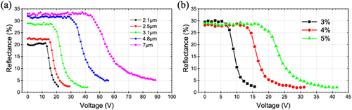
The observations identified a cell gap of 3μm as the optimal value for this combination. This specific cell gap ensures favorable brightness reflectance while maintaining a relatively low driving voltage. Therefore, we will fix the cell gap at 3μm for all subsequent parameter explorations. Moreover, the discussion in this section pertains specifically to green color (λc ≈ 540∼550 nm) cholesteric liquid crystals. For blue and red color cholesteric liquid crystals, a relatively smaller and larger cell gap, respectively, is needed to simultaneously achieve sufficiently high reflectance and low driving voltage.
Monomer concentration is a crucial factor determining the mode of polymer-stabilized liquid crystal (PSCLC). This study initially focuses on exploring the impact of different concentrations of RM257 – 3%, 4%, and 5% – on PSCLC reflective displays. Under a fixed polymerization temperature of 25°C, varying performances in terms of hysteresis were observed. The hysteresis values were 1.69, 1.72, and 2.23 V for decreasing monomer concentrations, respectively. Although, an increase in RM257 concentration resulted in a significant reduction in hysteresis. The driving voltage also increases simultaneously, as shown in Figure (b). This suggests a greater driving voltage is required to align the liquid crystal molecules to the desired state, indicating challenges in application for active matrix driving. Furthermore, the refractive index mismatch between the liquid crystal and polymer may lead to an increase in the scattering effect in the bright state as the polymer concentration rises. This phenomenon results in a slight decrease in reflectance (haze values of 13.1%, 16.9%, and 20%, respectively). The experimental results indicated that while 3% RM257 exhibited slightly larger hysteresis, its saturation voltage was 12.2 V, notably lower than values >20 V for 4% and 5% concentrations. Consequently, the aim is to further optimize hysteresis performance through subsequent experiments, taking into account parameters such as polymerization temperature.
Polymerization temperature is also a critical parameter, directly influencing the phase separation process during polymerization and leading to variations in the morphology and characteristics of the polymer structure. As depicted in Figure (a), the focus is on the trends at three different polymerization temperatures: 0°C, 15°C, and 25°C. According to the experimental results, it is observed that at lower polymerization temperatures, such as 0°C, hysteresis is indeed reduced. However, concurrently, driving voltage correspondingly increases. This phenomenon is attributed to the denser polymer structure at lower temperatures, providing a greater anchoring effect for the liquid crystal, necessitating a higher voltage to drive the liquid crystal molecules to the desired state. Additionally, the denser polymer structure appears to withstand higher voltages effectively under these conditions.
Figure 2. (a) RV curve at various polymerization temperatures for cholesteric liquid crystal (E7 CLC) mixed with 3% polymer monomer (RM257). (b) RV Curve at 25°C for cholesteric liquid crystal (E7 CLC) with varying concentration ratios of polymer monomers RM257 and M1.
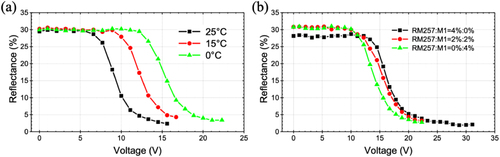
To gain a deeper understanding of the impact of different polymer monomer structures on electro-optical characteristics, a series of tests on RM257 and M1 were conducted. The primary distinction between the two monomers lies in the length of the carbon chain, with RM257 having a shorter chain than M1. As observed from Figure (b), the results indicate that at higher concentration ratio of RM257, the withstand voltage is relatively higher. Conversely, at higher concentration ratio of M1, the driving voltage decreases. This indicates that the increase in carbon chain length may effectively result in a sparser polymer structure, providing weaker anchoring. However, the stability characteristics of the polymer may decrease in comparison. Furthermore, with the increased concentration ratio of M1, the measured hysteresis values are 1.72, 1.55, and 2.92, respectively. From these results, it can be analyzed that the slightly larger hysteresis at RM257 4% may be due to a larger operation voltage. While the operation voltages for RM257 and M1 at proportions of 2%:2% and 0%:4% show minimal differences, the hysteresis differences are more pronounced. Therefore, based on the current experimental results, it is evident that although saturation voltage effectively decreases by adding polymer monomers with longer carbon chains, hysteresis also increases relatively.
Based on the experiments conducted so far, achieving both low hysteresis and sufficiently small saturation voltage is a relatively challenging task. Consequently, we switched the liquid crystal host to HTG, aiming to exploit its characteristics of larger dielectric anisotropy (Δϵ = 55–60) to achieve optical and electrical properties with low driving voltage and hysteresis. As depicted in Figure (a), HTG CLC, whether paired with RM257 or M1, exhibits smaller driving voltages compared to E7 CLC. This change in the liquid crystal host with higher dielectric anisotropy is evidently effective. However, it is noteworthy that HTG CLC paired with M1 at 4% concentration yields very low saturation voltage. Yet, the poor stability of the polymer results in a suboptimal contrast ratio between bright and dark states. Therefore, to further optimize the optical and electrical properties of this material system through polymerization conditions is necessary.
Figure 3. (a) RV curve at 25°C for cholesteric liquid crystal (E7 CLC and HTG CLC) with 4% polymer monomers RM257 and M1. (b) RV curve at different polymerization temperatures for cholesteric liquid crystal (HTG CLC) with 4% polymer monomer M1.
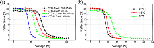
Building upon the results of different polymerization temperatures for E7 CLC, it is a good way to manipulate polymer structure by varying the polymerization temperature. Lower polymerization temperatures were found to create lower hysteresis and more stable polymer structures. Also, this was accompanied by an increase in saturation voltage. As shown in Figure (b), at a polymerization temperature of 15°C, in comparison to 25°C, there is an ideal combination of saturation voltage and withstand voltage. Consequently, the dark-state reflectance further decreased (from 2.9% to 1.73%), resulting in an improved bright-to-dark state contrast ratio. The next step involves confirming whether these conditions are suitable for active matrix driving schemes, considering factors such as hysteresis, response time, contrast ratio, and reliability.
According to Figure (a–c), measurements showed that when the voltage exceeds 12.2 V, the reflectance can drop below 4.5%. As the voltage continues to increase, the hysteresis increases from 0.8 to 2.17 V. Meanwhile, the contrast ratio can increase from 7.5 to 17.8. Additionally, in terms of response time, when the voltage is above 13.3 V, the sum of rise time and fall time can be less than 100 ms. Exceeding 15.6 V, the response time can drop below 42 ms, meeting the frame rate required for basic human visual persistence. This study also explores the sensitivity of the material's response time to temperature. At 40°C, the response time is approximately half of those at 25°C. Conversely, at 15°C, response time is approximately double. These results are related to variation in the viscosity of the liquid crystal. The device was also subjected to a maximum tolerable voltage of 16.7 V, repeating the application and release of voltage 500 times to observe its reliability. It was found that the reflectance of the bright and dark states was maintained at a certain level, demonstrating the device's high reliability.
Figure 4. Cholesteric liquid crystal with HTG as the host, polymerized at 15°C, and mixed with 4% M1. (a) Hysteresis and bright-dark state contrast ratio, (b) response time, (c) number of repeated voltage applications, and (d) reflective spectrum at different voltages.
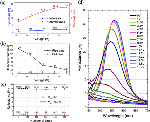
Based on the current research findings, after optimization, the driving voltage can be operated within 15 V to achieve a good bright-dark state contrast ratio (>10). This performance contributes to the application of the material in active matrix driving. In addition, the response time, above a specific voltage, can also meet the requirements for animated display effects. Although, this study may have met some of the most basic conditions for a reflective display capable of animation, there are still several challenges to overcome to achieve high-quality display. First, the response time at low voltages still be too long, which could necessitate the use of over-driving to quickly generate the grayscale display effect required at low voltages. Second, hysteresis increases with voltage, so if a higher bright-dark state contrast is desired, the performance of hysteresis could be unfavorable for driving. Third, as seen in Figure (d), it's apparent from the reflective spectrum at different voltages that the reflection center wavelength () undergoes a slight blue shift with increasing voltage. This phenomenon may be related to the Helfrich deformation [Citation9, Citation33–35] generated in PSCLC when voltage is applied, and it could significantly affect whether colors can be accurately displayed. Fourth, for active matrix driving, the voltage holding ratio (VHR) [Citation36–39] in the liquid crystal material is crucial, determining whether the panel can provide a stable voltage signal to the liquid crystal. It results in issues such as flicker, image sticking, and reduced reliability. If the above-mentioned issues can be addressed, compared to traditional reflective LCDs [Citation10–12], there could be improvements in aspects such as reflectance and color saturation. Moreover, even compared to the most mature reflective display technology on the market, such as electronic ink (e-ink) [Citation3–6], achieving continuous and rapid screen switching with better optical performance, would be a highly anticipated display technology.
4. Conclusions
This study explored the potential of utilizing cholesteric liquid crystal technology for animated reflective displays. The employment of reverse mode polymer-stabilized cholesteric liquid crystals (PSCLC) effectively reduced the inherent bistability of CLCs, leading to quicker transition times between bright and dark states. A thorough investigation into various parameters like cell gap, monomer concentration, polymerization temperature, and different monomer types and liquid crystal hosts, was conducted to assess the feasibility of using reverse mode PSCLCs for active matrix driving. By optimizing crucial parameters, including a cell gap of 3μm, a monomer concentration of 4% M1, a polymerization temperature of 15°C, and HTG as the liquid crystal host, a PSCLC device with impressive performance can be achieved. This research has shown that reverse mode PSCLCs can operate within a 15 V range, maintaining an impressive bright-dark state contrast ratio greater than 10, with response times under 42 ms. While this research has met essential requirements for animated displays, there is still room for enhancement in achieving higher-quality displays. The manipulation of these variables has not only allowed for the creation of a display suitable for animation but has also preserved the intrinsic benefits of CLC technology, such as eye protection and energy efficiency. This work opens up new avenues for applying CLC technology in active matrix driving for animated reflective displays, suggesting a new opportunity for this field.
Disclosure statement
No potential conflict of interest was reported by the author(s).
Additional information
Funding
Notes on contributors

Kuan-Wu Lin
Kuan-Wu Lin is currently a Ph.D. candidate in the Department of Photonics at National Sun Yat-sen University (NSYSU). His research interests include smart windows, advanced liquid crystal displays, and electrochemical analysis related to liquid crystals.

Jhih-Yi Lu
Jhih-Yi Lu received his Master's degree from National Sun Yat-sen University in 2023. He is currently working as an R&D engineer at Brilliant Optronics Corporation.

Heng-Yi Tseng
Heng-Yi Tseng received his Master's and Ph.D. degrees from National Sun Yat-sen University in 2012 and 2022, respectively. He is currently working as a principal engineer in the Display Technology Development Department at AUO Corporation.

Chien-Yi Lin
Chien-Yi Lin received his Master's degree from National Sun Yat-sen University in 2022. He is currently working as a senior engineer in the Display Technology Development Department at AUO Corporation.

Liang Ying Huang
Liang-Ying Huang received her B.S. degree in Applied Chemistry from National Yang Ming Chiao Tung University, Hsinchu, Taiwan. She is currently working in Cell Technology Development at AUO Corporation. Her current research focuses on liquid crystal devices design and material development.

Yi-Ling Lin
Yi-Ling Lin received her M.S. in Materials and Engineering Science from National Yang Ming Chiao Tung University, Taiwan in 2005. Since then, she has been working at AUO Corporation in Hsinchu, Taiwan, where she is currently engaged in the research and development of liquid crystals and alignment films.

Huan-Hsuan Chang
Huan-Hsuan Chang received his Ph.D. in the Department of Applied Chemistry from National Yang Ming Chiao Tung University in 2014. Since then, he has been working in cell technology development at AUO Corporation.

Tsung-Hsien Lin
Tsung-Hsien Lin is currently a Chair Professor in the Department of Photonics, National Sun Yat-sen University (NSYSU). He received B.S./M.S. degree in Physics and Ph.D. degree in Electro-Optics from National Cheng Kung University (Taiwan). He had served as the Chairman of the Department of Photonics, Vice President of Research and Development Office, CEO of Higher Education SPROUP Program at National Sun Yat-sen University. He has received the Distinguished Research Award (NSTC) in 2022 and 2018, 15th National Innovation Award, Distinguished Innovation & Startups Award (NSTC), Business Startup Award (Ministry of Economic Affairs), LITE-ON Gold Innovation Award, Ta-You Wu Memorial Award (NSTC), CES Innovation Award. The current research interests are photonic liquid crystal, smart window, phased antenna array, and advanced liquid crystal display. Prof. Lin has published over 100 scientific papers in international journals, including Nature Materials, Nature Communications, Applied Physics Reviews, Advanced Materials, and OPTICA.
References
- H. Chen, G. Tan, and S.-T. Wu, Ambient Contrast Ratio of LCDs and OLED Displays, Opt. Express 25, 33643–33656 (2017).
- S. Kim, H.J. Kwon, S. Lee, H. Shim, Y. Chun, W. Choi, J. Kwack, D. Han, M. Song, and S. Kim, Low-Power Flexible Organic Light-Emitting Diode Display Device, Adv. Mater. 23, 3511–3516 (2011).
- S.K. Eshkalak, M. Khatibzadeh, E. Kowsari, A. Chinnappan, W. Jayathilaka, and S. Ramakrishna, Overview of Electronic Ink and Methods of Production for Use in Electronic Displays, Opt. Laser Technol. 117, 38–51 (2019).
- Z.-L. Zhou, Q. Liu, J.-S. Yeo, G. Combs, B. Benson, M. Parent, J. Yang, J. Mabeck, S. Lam, and Y. Jeon, Development of Novel Electronic Inks for Print-Like Color Reflective Display (Hewlett-Packard Development Company, Palo Alto, CA, 2011).
- T. Koch, J.-S. Yeo, Z.-L. Zhou, Q. Liu, J. Mabeck, G. Combs, V. Korthuis, R. Hoffman, B. Benson, and D. Henze, Novel Flexible Reflective Color Media with Electronic Inks, J. Inf. Disp. 12, 5–10 (2011).
- O. Hanton, Z. Shen, M. Fraser, and A. Roudaut, FabricatINK: Personal Fabrication of Bespoke Displays Using Electronic Ink from Upcycled E Readers, in Proceedings of the 2022 CHI Conference on Human Factors in Computing Systems, New Orleans, LA, 2022, 1–15.
- Y. Li, D. Luo, and Z.H. Peng, Full-Color Reflective Display Based on Narrow Bandwidth Templated Cholesteric Liquid Crystal Film, Opt. Mater. Express 7, 16–24 (2017).
- W. St. John, Z.J. Lu, and J. Doane, Characterization of Reflective Cholesteric Liquid-Crystal Displays, J. Appl. Phys. 78, 5253–5265 (1995).
- S.-Y. Lu, and L.-C. Chien, A Polymer-Stabilized Single-Layer Color Cholesteric Liquid Crystal Display with Anisotropic Reflection, Appl. Phys. Lett. 91, 131119 (2007).
- D.K. Yang, J.L. West, L.C. Chien, and J.W. Doane, Control of Reflectivity and Bistability in Displays Using Cholesteric Liquid Crystals, J. Appl. Phys. 76, 1331–1333 (1994).
- D.-L. Ting, C.-L. Chen, C.-L. Kuo, C.-K. Wei, C.-Y. Liu, Y.-H. Lu, H.-F. Shih, C.-W. Hao, and S.-T. Wu, Full-Color Reflective-Type TFT-LCD, in Display Technologies II, Taipei, Taiwan, SPIE, 1998, 106–112.
- D.L. Ting, W.C. Chang, C.Y. Liu, J.W. Shiu, C.J. Wen, C.H. Chao, L.S. Chuang, and C.C. Chang, A High Brightness and High Contrast Reflective LCD with Micro Slant Reflector (MSR), SID Symp. Dig. Tech. Pap. 30, 954–957 (1999).
- W.S. John, W. Fritz, Z. Lu, and D.-K. Yang, Bragg Reflection from Cholesteric Liquid Crystals, Phys. Rev. E 51, 1191 (1995).
- V. Belyakov, V.E. Dmitrienko, and V. Orlov, Optics of Cholesteric Liquid Crystals, Sov. Phys. Uspekhi 22, 64 (1979).
- D. Coates, Development and Applications of Cholesteric Liquid Crystals, Liq. Cryst. 42, 653–665 (2015).
- Z. Li, P. Desai, R. B. Akins, G. Ventouris, and D. Voloschenko, Electrically Tunable Color for Full-Color Reflective Displays, in Liquid Crystal Materials, Devices, and Applications VIII. San Jose, CA, SPIE, 2002, 7–13.
- X.-Y. Huang, A. A. Khan, D. J. Davis, G. M. Podojil, C. M. Jones, N. Miller, and J. W. Doane, Full-Color Reflective Cholesteric Liquid Crystal Display, in Liquid Crystal Materials, Devices, and Applications VII, San Jose, CA, SPIE, 1999, 120–126.
- D.-K. Yang, J.W. Doane, Z. Yaniv, and J. Glasser, Cholesteric Reflective Display: Drive Scheme and Contrast, Appl. Phys. Lett. 64, 1905–1907 (1994).
- M. Pfeiffer, A High-Information-Content Reflective Cholesteric Display, in SID International Symposium Digest of Technical Papers, Orland, 1995, 706–709.
- X.Y. Huang, D.K. Yang, P. Bos, and J. Doane, Dynamic Drive for Bistable Reflective Cholesteric Displays: A Rapid Addressing Scheme, J. Soc. Inf. Disp. 3, 165–168 (1995).
- D.-K. Yang, X.-Y. Huang, and Y.-M. Zhu, Bistable Cholesteric Reflective Displays: Materials and Drive Schemes, Annu. Rev. Mater. Sci. 27, 117–146 (1997).
- X.Y. Huang, D.K. Yang, and J.W. Doane, Transient Dielectric Study of Bistable Reflective Cholesteric Displays and Design of Rapid Drive Scheme, Appl. Phys. Lett. 67, 1211–1213 (1995).
- X.Y. Huang, J. Doane, and D.K. Yang, The Transient Response and Dynamic Drive of Cholesteric Liquid-Crystal Displays, J. Soc. Inf. Disp. 5, 179–187 (1997).
- C.-C. Li, C.-W. Chu, C.-W. Chen, H.-C. Jau, C.-H. Lee, C.-T. Wang, Z.-C. Li, and T.-H. Lin, Optimization of Dynamic Drive Scheme for Cholesteric LCDs, J. Disp. Technol. 12, 35–39 (2016).
- F. Yu and H.-S. Kwok, A New Driving Scheme for Reflective Bistable Cholesteric Liquid Crystal Displays, in Society for Information Display International Symposium Digest of Technical Papers, 1997.
- Y. Zhu, and D.K. Yang, P-82: Cumulative Drive Schemes for Bistable Reflective Cholesteric LCDs, SID Symp. Dig. Tech. Pap. 29, 798–801 (1998).
- M. Xu, and D.-K. Yang, Dual Frequency Cholesteric Light Shutters, Appl. Phys. Lett. 70, 720–722 (1997).
- Q. Wang, Z. Ma, H. Li, X. Li, and X. Huang, Effects of Curing Temperature and UV Intensity on Electro-Optical Properties of PSCT Reverse-Mode Light Shutters, in Liquid Crystals: Chemistry, Physics, and Applications, Krynica Zdroj, SPIE, 2000, 353–358
- X. Li, Y. Guo, H. Huai, Y. Yang, Y. Sun, C. Zhang, and Y. Sun, The Effect of Monomer and Chiral Dopant Content on Reverse-Mode Polymer Stabilized Cholesteric Liquid Crystal Display, J. Mol. Liq. 309, 113112 (2020).
- H. Ren, and S.-T. Wu, Reflective Reversed-Mode Polymer Stabilized Cholesteric Texture Light Switches, J. Appl. Phys. 92, 797–800 (2002).
- F. Ahmad, M. Jamil, and Y.J. Jeon, Reverse Mode Polymer Stabilized Cholesteric Texture (PSCT) Light Shutter Display – a Short Review, J. Mol. Liq. 233, 187–196 (2017).
- K. Yang, Measurements of Empty Cell Gap for Liquid-Crystal Displays Using Interferometric Methods, J. Appl. Phys. 64, 4780–4781 (1988).
- H. Xianyu, T.-H. Lin, and S.-T. Wu, Rollable Multicolor Display Using Electrically Induced Blueshift of a Cholesteric Reactive Mesogen Mixture, Appl. Phys. Lett. 89, 091124 (2006).
- H. Nemati, D.-K. Yang, K.-L. Cheng, C.-C. Liang, J.-W. Shiu, C.-C. Tsai, and R. Zola, Effect of Surface Alignment Layer and Polymer Network on the Helfrich Deformation in Cholesteric Liquid Crystals, J. Appl. Phys. 112, 124513 (2012).
- M. Yu, H. Yang, and D.-K. Yang, Stabilized Electrically Induced Helfrich Deformation and Enhanced Color Tuning in Cholesteric Liquid Crystals, Soft Matter. 13, 8728–8735 (2017).
- T. Nakanishi, T. Takahashi, H. Mada, and S. Saito, Transient Behavior of Voltage Holding Ratio in Nematic Liquid Crystal Cells, Jpn. J. Appl. Phys. 41, 3752 (2002).
- P.-S. Chen, C.-C. Huang, Y.-W. Liu, and C.-Y. Chao, Effect of Insulating-Nanoparticles Addition on Ion Current and Voltage-Holding Ratio in Nematic Liquid Crystal Cells, Appl. Phys. Lett. 90, 211111 (2007).
- M. OH-E, Advantageous Voltage-Holding Ratio Characteristics Induced by in-Plane Electric Fields, and the Optimization Concept of Liquid Crystals for an in-Plane Switching Electro-Optical Effect, Liquid Crystals 25, 699–709 (1998).
- N. Sasaki, Simulation of the Voltage Holding Ratio in Liquid Crystal Displays with a Constant Charge Model, Jpn. J. Appl. Phys. 37, 6065 (1998).