 ?Mathematical formulae have been encoded as MathML and are displayed in this HTML version using MathJax in order to improve their display. Uncheck the box to turn MathJax off. This feature requires Javascript. Click on a formula to zoom.
ABSTRACT
In this work, the time dependent flow of an incompressible couple stress fluid passing two infinite parallel plates is investigated. The fluid motion is generated by applying a constant pressure gradient together with a sudden motion of one of the two plates. The linear slip velocity and the vanishing couple stresses on the boundary are applied on both plates. A generalized solution is obtained analytically by utilizing the integral Laplace transform together with the state space technique in the Laplace domain. The inversion of Laplace transform is obtained numerically by using a standard numerical method adopted by Honig and Hirdes. The effects of couple stress viscosity coefficient and slip parameters on both plates are studied numerically. The results show that the increase in the couple stress and slip coefficients results in a decrease in the fluid velocity in the case of stationary plates. However the velocity of the fluid is amplified by the increase of these parameters when the upper plate is set in motion.
Introduction
Throughout the last four centuries, the study of non- Newtonian fluids has gained great attention by mathematicians and physicists such as Newton, Navier, and Euler, due to its importance in industrial, scientific and technological fields. Moreover, they proposed many models and different equations to explain the behaviour of such fluids. Couple stress fluids model is one of the most significant non-Newtonian fluid models which has been introduced by Stokes in 1964 [Citation1]. It gives a simple generalization for the classical Navier-Stokes theory. In this model, the polar effects such as the presence of body couples and couple stresses are assumed to contribute to the fluid flow. Its equation of motion is similar to that of classical Navier-Stokes theory in addition to an extra term of higher order. The stress tensor is non-symmetric and an additional tensor namely couple stress tensor exist. This theory models many types of fluids microstructure e.g. liquid crystals, muddy water and animal blood [Citation2].
Numerous studies have been recorded in the theory of couple stress fluids. Devakar and Iyengar considered Stokes’ problems for couple stress fluid using the classical no-slip condition [Citation3]. They also discussed the run up flow between parallel plates with the same boundary conditions [Citation4]. In addition, they investigated the generalized Stokes’ problem [Citation5]. In recent years, Saad and Ashmawy studied the unsteady plane Couette flow of couple stress fluid between two parallel plates with slip condition [Citation6]. The latter solved the problem of couple stress fluid through an infinite circular cylinder [Citation7].
In this paper, we investigate the motion of an incompressible couple stress fluid flow limited between two parallel plates keeping one of the two plates stationary while the other is set in motion in addition to the presence of a time dependent pressure gradient. The Laplace transform together with the state space technique are applied to obtain the solution of the problem in the Laplace domain. The Laplace transform is inverted to the physical domain numerically using a standard algorithm adopted by Honig and Hirdes [Citation8]. The solution of the problem is discussed through graphs.
Formulation of the problem
Assuming that there is no body forces and body couples, the unsteady flow of an incompressible couple stress fluid is governed by the following differential equations [Citation1,Citation2]:
Conservation of mass
(1)
(1)
Conservation of momentum
(2)
(2)
where
and
are respectively the velocity vector, pressure at any point, and the fluid density. The viscosity coefficient is denoted by µ, and
is the couple stress viscosity coefficient.
The non-symmetric stress and couple stress tensors are defined respectively by [Citation1,Citation2]
(3)
(3)
(4)
(4)
where
and
are the Kronecker delta and alternating tensor respectively.
is the couple stress coefficient, and m is the trace of the couple stress tensor.
The rate of deformation vector and the vorticity vector, respectively, are evaluated by
(5)
(5)
(6)
(6)
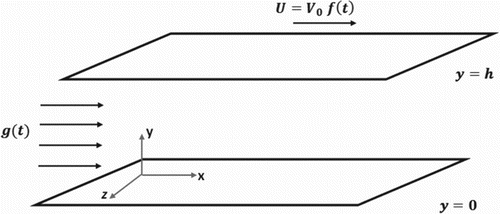
Let us consider now the unsteady flow of an incompressible couple stress fluid flanked by two infinite horizontal parallel plates separated by distance “h”. Initially, both plates and the fluid are at rest. Suddenly, the upper plate is moved with velocity U=
, where
is a constant with velocity dimensions and
is an arbitrary function of time. Instantaneously, a time dependent pressure gradient is applied in the direction of the positive x-axis. The velocity of the fluid has only one non-vanishing component. Hence, the velocity vector can be written as
().
The velocity field “” automatically satisfied the equation of conservation of mass, and using this quantity, the equation of conservation of momentum reduces to
(7)
(7)
Initially, the fluid is at rest.
Hence,
(8)
(8)
The slip boundary conditions applied on the two plates are given by [Citation9–11]
(9)
(9)
(10)
(10)
The parameters
and
represent, respectively, the slip coefficients of the lower and upper plates. These parameters depend only on the fluid nature and the material of the solid boundaries, and they vary between zero and infinity.
The vanishing couple stress conditions at the boundaries are the following
(11)
(11)
(12)
(12)
Now, consider the non-dimensional variables
(13)
(13)
Using these variables, we can write the differential equation (7) in the form
(14)
(14)
Such that,
(15)
(15)
In addition, we can write the initial and boundary conditions (8)–(12) in terms of the non-dimensional variables (13), after dropping the hats, as
(16)
(16)
(17)
(17)
(18)
(18)
(19)
(19)
(20)
(20)
where,
and
.
Taking the Laplace transform of equation (14) and applying the initial condition (16), we get
(21)
(21)
Also, the boundary conditions (17)-(20), after applying Laplace transform, are reduced to
(22)
(22)
(23)
(23)
(24)
(24)
(25)
(25)
The formula of Laplace transform is given as
(26)
(26)
State space approach
A state space is a mathematical model of a physical system represented as a set of input, output and state variables connected by a differential equation in matrix form. The concept of the state of a dynamic system refers to a minimum set of variables, namely state variables, which accurately describe the system. This technique is suitable for illustrating the high-order dimensional systems since it reduces its order and makes it easy to solve. The state space method has been used extensively by many authors to solve complicated problems in the theory of thermo-elasticity [Citation12–14]. Other researchers utilized the same technique to investigated micropolar fluid flow problems [Citation15–17]. To our knowledge, no one has used the aforementioned technique in the theory of couple stress fluids yet.
Solution using state space approach
To apply the state space technique, we first write the differential equation (21) in the matrix form
(27)
(27)
where,
Then (21) becomes
(28)
(28)
The formal solution of the differential equation (27) is found to be
(29)
(29)
The characteristic equation of the square matrix
is given by
(30)
(30)
The roots of the above characteristic equation are ±
and ±
where
The expansion of Maclaurin series of
is defined by
(31)
(31)
Since every square matrix satisfies its own characteristic equation “Cayley-Hamilton theorem”, we can write
(32)
(32)
So, we can express
and the higher powers of A in terms of I, A,
,
, where I is the unit matrix of order 4. Therefore, we can write
as a finite series in the form
(33)
(33)
Moreover, using the fact that ±
and ±
are the characteristic roots of
, we can write
(34)
(34)
(35)
(35)
Solving this system allow us to determine
and
which depend on y and s,
where,
.
As a result, and after substituting the matrices in the expression (33) the matrix L(y, s), is completely obtained. The elements of
(i, j = 1 2,3,4) are given below
We can now rewrite the solution (29) in terms of as
(36)
(36)
(37)
(37)
By definition,
(38)
(38)
which can be reduced to a finite series using “Cayley Hamilton Theorem”, such as
(39)
(39)
Then,
(40)
(40)
(41)
(41)
Therefore, the solution can be written in the form
(42)
(42)
(43)
(43)
(44)
(44)
(45)
(45)
Such that,
After applying the boundary conditions (23),(25),we can get the two unknowns
and
assuming that
(i, j = 1,2,3,4) are the values of
at
such as
where,
Inversion of laplace transform numerically
In order to invert the Laplace transforms obtained we employ the standard numerical inversion algorithm adopted by Honig and Hirdes [Citation8]. In this algorithm, the inverse Laplace transform of the function is approximated by
(46)
(46)
The number N is a sufficiently large integer chosen such that
where
a small positive number that corresponds to the degree of accuracy required and b is a positive free parameter that must be greater than the real part of all singularities of
. In this regards, we consider three cases listed below.
Numerical results
In this section, we present the obtained results graphically for the variation of the velocity through the mean of the inversion numerical technique outlined above. Two different cases are considered.
Case1: flow due to oscillatory motion of the upper plate with no pressure gradient
In this case, we assume that the upper plate is set in motion with a an oscillating velocity given by , where
is the angular velocity, with no pressure gradient.
Case2: flow due to oscillatory pressure gradient with stationary plates
In this case, the two plates are assumed to be stationary and the motion is generated by applying a time dependent pressure gradient of the form
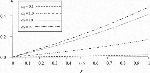
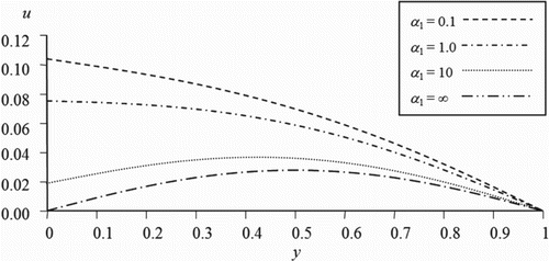
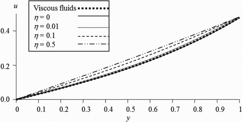
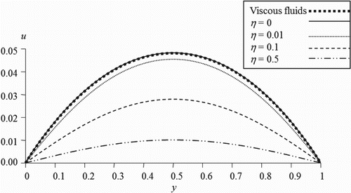
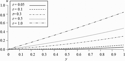
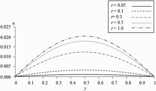
In the figures illustrated in this section, we plot the velocity of the couple stress fluid flow versus the distance between the two plates for different values of the time, slip and couple stress viscosity parameters. shows the variation of the velocity for different values of the slip parameter of the upper plate while the other parameters are kept fixed. It is observed that, as the slip parameter increases the fluid velocity increases near the moving plate. However, reveals that as the slip parameter on the stationary plate increases, the fluid velocity decreases. This indicates that the more the fluid slips at the boundary the less its velocity is affected by the motion of the boundary. Figures and illustrate the velocity profile for various values of the couple stress viscosity parameter in the first and second case respectively. It is noticed that the fluid velocity is proportional to the couple stress parameter in the first case while the trend is reversed when the motion is generated by a pressure gradient. As expected, it is observed from Figures and that our results when the couple stress viscosity parameter is taken zero is coincident with the previous results available in the literature for the case of classical viscous fluids [Citation18]. On the other hand, Figures and represent the behaviour of the velocity for different values of time parameter. It can be seen that the increase of the time parameter enhances the magnitude of the fluid velocity in both cases.
Conclusion
This work focuses on the study of the unsteady motion of an incompressible couple stress fluid between two infinite parallel plates. The motion is generated by letting one of the two plates starts to move with a time dependent velocity while the other is set stationary in addition to the presence of pressure gradient. The results showed that when the two plates are kept stationary, the slip parameters have an opposing effect on the velocity of the fluid. However, the fluid velocity is amplified by the slip parameter in case of a moving plate with no pressure gradient. Similarly, the velocity field is affected by the presence of the couple stress coefficient considerably. Moreover, the velocity of the fluid is remarkably increased with the time parameter.
Disclosure statement
No potential conflict of interest was reported by the authors.
ORCID
S. S. Ilani http://orcid.org/0000-0002-4050-3652
E. A. Ashmawy http://orcid.org/0000-0002-1223-2760
References
- Stokes VK. Couple stresses in fluids. Phys Fluids. 1966;9:1709–1715. doi: 10.1063/1.1761925
- Stokes VK. Theories of fluids with microstructure. New York (NY): Spinger; 1984.
- Devakar M, Iyengar TKV. Stokes’ problems for an incompressible couple stress fluid. Nonlinear Anal-Model. 2008;1(2):181–190.
- Devakar M, Iyengar TKV. Run up flow of couple stress fluid between parallel plates. Nonlinear Anal-Model. 2010;15(1):29–37.
- Devakar M, Iyengar TKV. Generalized Stokes’ problems for an incompressible couple stress fluid. Int J Math Comput Sci Eng. 2014;8(1):113–116.
- Saad HS, Ashmawy EA. Unsteady plane coquette flow of an incompressible couple stress fluid with slip boundary conditions. Int J Med Health Sci Res. 2016;3(7):85–92.
- Saad HS, Ashmawy EA. Unsteady slip flow of a couple stress fluid through an infinite circular cylinder. Int J App Eng Res. 2016;11(21):10563–10573.
- Honig G, Hirdes U. A method for numerical inversion of laplace transform. J Comp Appl Math. 1984;10:113–132. doi: 10.1016/0377-0427(84)90075-X
- Ashmawy EA. Unsteady Couette flow of a micropolar fluid with slip. Meccanica. 2012;47:85–94. doi: 10.1007/s11012-010-9416-7
- Keh HJ, Chang YC. Slow motion of a slip spherical particle perpendicular to two plane walls. J Fluids Struct. 2016;22:647–661.
- Ellahi R, Alamri SZ, Basit A, et al. Effects of MHD and slip on heat transfer boundary layer flow over a moving plate based on specific entropy generation. J Taibah Univ Sci. 2018;12(4):476–482. doi: 10.1080/16583655.2018.1483795
- Sherief HH, Anwar MN. State space approach to two-dimensional generalized thermoelasticity problems. J Thermal Stresses. 1994;17:567–590. doi: 10.1080/01495739408946280
- Youssef HM. State-space approach on generalized thermo elasticity for an infinite material with a spherical cavity and variable thermal conductivity subjected to ramp-type heating. CAMQ. 2005;13(4):369–390.
- Sherief HH, El sayed AM. State space approach to two-dimensional generalized micropolar thermoelasticity. ZAMP. 2015;66(3):1249–1265.
- Devakar M, Iyengar TKV. Run up flow of an incompressible micropolar fluid between parallel plates-A state space approach. Appl Math Model. 2011;35:1751–1764. doi: 10.1016/j.apm.2010.10.007
- Devakar M, Iyengar TKV. Unsteady flows of a micropolar fluid between parallel plates using state space approach. Eur Phys J Plus. 2013;128(4):1–13. doi: 10.1140/epjp/i2013-13041-1
- Slayi SA, Ashmawy EA. Time dependent slip flow of a micropolar fluid between two parallel plates through state space approach. Global J Pure Appl Math. 2016;12(2):827–836.
- White FM. Viscous fluid flow. New York (NY): Mc-Graw Hill Inc; 1991.

