
 ?Mathematical formulae have been encoded as MathML and are displayed in this HTML version using MathJax in order to improve their display. Uncheck the box to turn MathJax off. This feature requires Javascript. Click on a formula to zoom.
Abstract
This work investigates the unsteady natural convection flow of a viscous, incompressible and electrically conducting fluid near an infinite vertical plate with ramped temperature and ramped motion. A unified closed form solution is obtained for the velocity field and skin friction coefficient corresponding to the case when the magnetic field fixed relative to the fluid or the moving boundary. It is assumed that the boundary plate has a ramped temperature profile and ramped motion subject to a uniform transverse magnetic field under the supposition of negligible induced magnetic field. Exact solutions of energy and momentum equations are obtained using the Laplace transform techniques. Graphical representations are attained for different values of the Prandtl number, magnetic field and heat sink parameter. Results show that wall ramped temperature and ramped motion tend to decrease fluid temperature, velocity, Nusselt number and skin friction.
Nomenclature
| = | Dimensional time | |
| = | Velocity | |
| = | Dimensionless velocity | |
| = | Wall temperature | |
| = | Initial temperature | |
| = | Dimensional heat generation term | |
| = | Co-efficient of heat generation | |
| = | Constant magnetic flux density | |
| = | Gravitational acceleration | |
| = | Hartmann number | |
| = | Dimensionless volume flow rate | |
| = | Prandtl number | |
| = | Dimensionless heat sink | |
| = | Specific heat at constant pressure | |
| = | Dimensionless time |
Greek letters
| = | Fluid kinematic viscosity | |
| = | Skin friction | |
| = | Electrical conductivity of the fluid | |
| = | Density | |
| = | Thermal conductivity of the fluid | |
| = | Coefficient of thermal expansion |
1. Introduction
Rossow [Citation1] was the first to study the hydrodynamic behaviour of the boundary layer on semi-infinite plate in the presence of a uniform transverse magnetic field. Convection is found in the rising plume of hot air from fire, oceanic current and sea wind formation. In fluid engineering, convection is commonly visualized in the formation of microstructure during the cooling of metal, MHD generator, MHD pumps, accelerators and flow meters, plasma studies, nuclear reactors, boundary-layer flow control, geothermal energy extractions, etc.
Over the past decades, researchers have investigated a number of unsteady free convection flow near a vertical plate under different sets of thermal conditions at the boundaries. The study continues to receive attention in the literature due to their important industrial and technological applications such as early stage of melting and in transient heating of insulating air gap by input at the start-up of furnaces. It provides the flow mechanism in some types of solar heating and ventilating passive systems. In modern electronic equipment, the vertical circuit boards include heat generating elements, and this situation can be modelled by parallel heated plates with the upward flow in the intervening space [Citation2]. Industrial applications such as underground disposal of radioactive waste materials, storage of foodstuffs, exothermic and/or endothermic chemical reactions, heat removal from nuclear fuel debris and dissociating fluids in packed bed reactors, etc. the heat generating/absorbing effects are of much significance.
Keeping in view these facts, free convection flow past a vertical plate in the presence of a transverse magnetic field has been investigated by a number of researchers. However, there exist several problems of physical interest, which may require non-uniform or arbitrary wall conditions. Considering this fact, several researchers [Citation3–6] investigated the problems of free convection near a vertical plate with a ramped wall temperature. Seth and Ansari [Citation7] considered hydro-magnetic natural convections flow past an impulsively moving vertical plate embedded in a porous medium with ramped wall temperature in the presence of thermal diffusion with heat absorption. Later Seth et al. [Citation8] extended the work of Seth and Ansari [Citation7] to include the effect of rotation. Nandkeolyar and Das [Citation9] studied unsteady MHD free convection flow of a heat absorbing dusty fluid past a flat plate with ramped wall temperature. G. S. Seth et al. [Citation10] studied the unsteady hydro-magnetic Couette flow within a porous channel. The fluid flow within the channel is induced due to the impulsive and uniformly accelerated motion of the lower plate of the channel. The magnetic lines of force are assumed to be fixed relative to the moving plate. They concluded that the suction exerts retarding influence on the fluid velocity whereas injection has an accelerating influence on it.
Jha et al. [Citation11] studied natural convection flow of heat generating or absorbing fluid near a vertical plate with ramped temperature and considered two cases, plate with continuous ramped temperature and the other with isothermal temperature. Jha and Jibril [Citation12] studied the MHD flow due to ramped motion of the boundary and observed that the velocity of the fluid in the case of ramped motion of the plate is always less than that of the flow induced by impulsive moving plate, but the analysis was done in the absence of ramped temperature field. Seth and Nandkeolyar [Citation13] studied MHD natural convection flow with radiative heat transfer past an impulsively moving plate with ramped wall temperature. Again, Seth et al. [Citation14] investigated hydro-magnetic natural convection flow with heat and mass transfer of a chemically reacting and heat absorbing fluid past an accelerated moving plate with ramped temperature and ramped surface concentration through a porous medium. Chandran et al. [Citation15] investigated natural convection near a vertical plate with ramped wall temperature. Ellahi et al. [Citation16] studied the effect of MHD and slip on heat transfer boundary layer flow over a moving plate based on specific enthropy generation.
Despite all these contributions, to the best of authors’ findings, no work has been analytically performed to account for combined ramped motion and ramped temperature of the boundary. The aim of the present study is to investigate the unsteady magneto hydrodynamic free convection flow of heat generating/absorbing electrically conducting fluid near a vertical plate with a ramped temperature and ramped motion.
2. Mathematical formulation
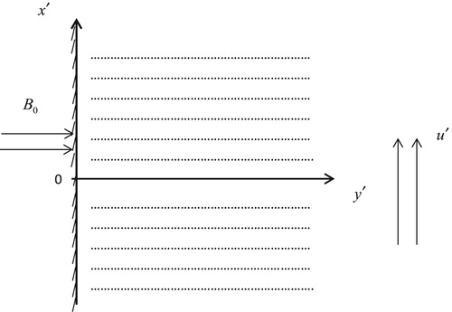
Consider an unsteady MHD natural convection flow of viscous, incompressible and electrically conducting fluid due to ramped temperature and ramped motion near a vertical plate. Figure shows the physical configuration of the flow, an arbitrary origin is chosen on the wall, the axis is taken along the wall in the upwards direction and the axis
is taken perpendicular to it in the fluid which is permeated by a uniform transverse magnetic field
applied parallel to the y-axis. At time
, the fluid, the plate and the magnetic lines of force are at rest with constant temperature
when the time is greater than zero that is
, the temperature of the plate is increased or decreased to
, and it begins to move in its plane with a velocity proportional to
, when
and thereafter
is maintained at constant temperature
. The main aim is to analyse MHD unsteady natural convection flow of heat generating or absorbing fluid with ramped temperature and ramped motion. The flow is assumed to be laminar, and the effect of the pressure gradient is neglected, the flow is caused by the ramped motion of the plate. The magnetic Reynold number of the flow is assumed to be small enough so that the induced magnetic field can be neglected. Here the physical variable becomes a function of the time variable
and the space variable
only as a result of the boundary layer approximation.
Figure 1. Physical configuration.
The dimensional momentum and energy equation together with the boundary conditions of the flow problems are given by
(1)
(1)
(2)
(2) where
is the velocity in
direction,
is the temperature of the fluid,
is the acceleration due to gravity,
is the volumetric co-efficient of thermal expansion,
is the kinematic viscosity,
is the density,
is the ramped function and
is the specific heat of the fluid at constant pressure.
The initial and boundary conditions are
(3)
(3)
(4)
(4)
(5)
(5)
(6)
(6)
(7)
(7)
(8)
(8) where
(9)
(9)
(10)
(10) where
is the Heaviside unit step function defined by
(11)
(11)
(12)
(12)
2.1. Non-dimensionless quantities
(13)
(13)
Using the non-dimensional quantities above, Equations (Equation1(1)
(1) ) and (Equation2
(2)
(2) ) becomes
(14)
(14)
(15)
(15)
According to the above non-dimensional process, the characteristic time can be defined as
(16)
(16)
The initial and boundary conditions in the non-dimensional form are
(17i)
(17i)
(17ii)
(17ii)
(17iii)
(17iii)
(17iv)
(17iv)
(17v)
(17v)
2.2. Laplace transform
(18)
(18)
(19)
(19) p > 0 (p being Laplace transform parameter).
Applying Laplace transform on Equations (Equation14(14)
(14) ) and (Equation15
(15)
(15) ) together with the initial and boundary conditions in non-dimensional form we obtain
(20)
(20)
(21)
(21)
The initial and boundary conditions in non-dimensional form are
(22)
(22)
(23)
(23)
(24)
(24)
The solution of Equations (Equation20(17iv)
(17iv) ) and (Equation21
(17v)
(17v) ) subject to the boundary conditions (24) and using the method of undetermined coefficient is given by
(25)
(25)
(26)
(26)
Taking the inverse Laplace transform of Equations (Equation25(21)
(21) ) and (Equation26
(22)
(22) ) the exact solution for the fluid temperature and fluid velocity is obtained and expressed in the following form after simplification.
(27)
(27)
(28)
(28) where H (t−1) is the unit step function.
(29)
(29)
2.3. Nusselt number and skin friction
The expression of skin friction coefficient and Nusselt number, which are the shear stress at the plate and measures of heat transfer rate on the boundary respectively, are presented in the following form:
(30)
(30)
(31)
(31)
3. Results and discussion
To investigate the effects of the various flow parameters suitable values of corresponding to the case of gas and water respectively, were chosen to depict the flow behaviour graphically.
Temperature profile for different values of time is presented in Figure . It shows that there is an enhancement in fluid temperature as time progresses. The effect of Pr on the flow is depicted in Figure it shows that the temperature decays with distance. For fluid with large Pr, the temperature decays faster with distance, which makes the thermal boundary layer to decrease. This is predictable since fluid with large Pr has low thermal diffusivity and hence heat penetration is less when Pr is large. For fluid with low Pr the temperature increases and thereby increasing the thermal boundary layer. Figure shows the effect of the heat sink in the channel. As the heat sink parameter
increases, the temperature decreases. Since increase in the heat sink parameter implies the reduction of heat in the channel therefore, it gradually decreases the fluid temperature.
Figure 2. Temperature profile for different values of .
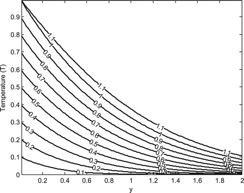
Figure 3. Temperature profile for different values of .
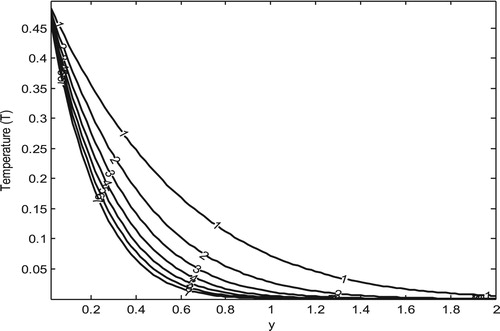
Figure 4. Temperature profile for different values of .
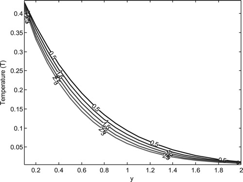
Figure displays the variation of velocity for different values of time , it is found that there is an enhancement in fluid velocity as time progresses. Figure shows the variation of velocity profile for different values of the heat sink
, from this figure, it is clear that velocity decreases with an increase of the heat sink parameters
this is projected since heating takes place progressively. Figure illustrates the variation of velocity profile for different values of magnetic field
. It shows that velocity decreases on increasing magnetic parameter
in the boundary layer region.
Figure 5. Velocity profile for different values of .
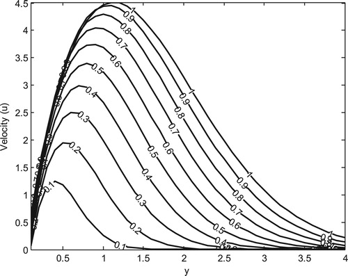
Figure 6. Velocity profile for different values of .
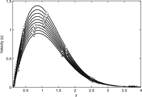
Figure 7. Velocity profile for different values of .
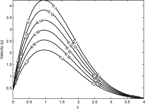
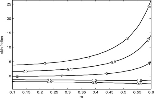
Figure shows the variation of Nusselt number for different values of Pr, it shows that there is an enhancement in the rate of heat transfer at the plate as Pr increases. Figure depicts the variation of Nusselt number versus heat sink for different values of Pr, it shows that the Nusselt number increases on increasing Pr. This implies that an increase in heat absorption increases the rate of heat transfer at this wall. Figure displays the variation of skin friction versus time for different values of Pr, it shows that the skin friction decreases on increasing Pr over time, which means the friction that occurs between the fluid and the solid surface increase as time progresses. Figure shows the variation of skin friction versus heat sink for different values of Pr, it shows that as the heat sink increases, there is a decrease in skin friction with an increase in Pr, this means that heat absorption has a retarding effect on the friction between the fluid and the solid surface. Figure demonstrates the variation of skin friction versus Hartmann’s number for different values of Pr, it Shows that Hartmann’s number increases the shear stress of the fluid this implies that the application of magnetic field to an electrically conducting fluid increase the friction between the fluid and the solid surface.
Figure 8. Variation of Nusselt number for different values of
.
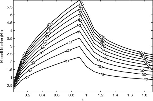
Figure 9. Variation of Nusselt number for different values
.
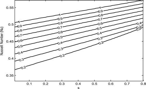
Figure 10. Variation of skin friction for different values of .
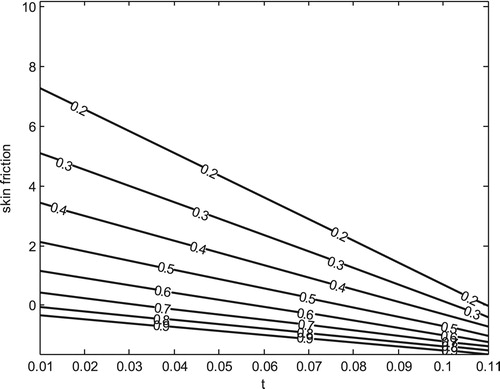
Figure 11. Variation of skin friction for different values of .
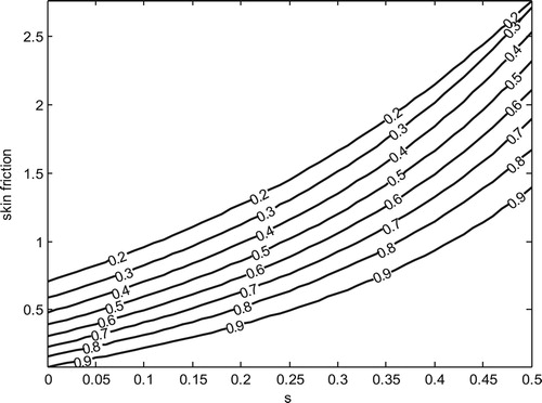
Figure 12. Variation of skin friction for different values of .
4. Conclusion
This study presents a theoretical investigation of unsteady MHD natural convection flow near a vertical plate with ramped wall temperature and ramped motion of the boundary plate. The significant findings are summarized below:
There is an enhancement in fluid temperature and velocity as time progresses despite the ramped temperature and motion of the boundary;
Fluid with large Pr decreases faster with channel width, which makes thermal boundary layer to decrease. This is expected since fluid with large Pr has low thermal diffusivity and hence heat penetration is less when Pr is large;
Fluid temperature decreases with an increase in heat absorption;
Magnetic field decrease fluid velocity.
Disclosure statement
No potential conflict of interest was reported by the authors.
ORCID
Khadijah K. Lawal http://orcid.org/0000-0001-6638-5730
Haruna M. Jibril http://orcid.org/0000-0001-7869-1807
References
- Rossow VJ. On flow of electrically conducting fluids over a flat plate in the presence of a transverse magnetic field, NACA rept. 1358; 1958.
- Al-Nimr MA. Analytical solution for transient laminar fully developed free convection in vertical concentric annuli. Int J Heat Mass Transf. 1993;36:2385–2395. doi: 10.1016/S0017-9310(05)80122-X
- Zakaria MN, Hussanan A, Khan I, et al. The effects of radiation on free convection flow with ramped wall temperature in Brinkman type fluid. J Teknologi. 2013;62:33–39.
- Kundu PK, Das K, Acharya N. Flow features of a conducting fluid near an accelerated vertical plate in porous medium with ramped wall temperature. J Mech. 2014;30:277–288. doi: 10.1017/jmech.2014.14
- Samiulhaq, Ahmed S, Vieru D, et al. Unsteady magnetohydrodynamic free convection flow of a second grade fluid in a porous medium with ramped wall temperature. Plos One. 2014;9:e88766. doi: 10.1371/journal.pone.0088766
- Samiulhaq, Khan I, Ali F, et al. Free convection flow of a second-grade fluid with ramped wall temperature. Heat Transf Res. 2014;45:579–588. doi: 10.1615/HeatTransRes.2014007241
- Seth GS, Ansari MS. MHD natural convection flow past an impulsively moving vertical plate with ramped wall temperature in the presence of thermal diffusion with heat absorption. Int J Appl Mech Eng. 2010;15:199–215.
- Seth GS, Nandkeolyar R, Ansari MS. Effect of rotation on unsteady on unsteady hydro magnetic natural convection flow past an impulsively moving vertical plate with thermal diffusion and heat absorption. Int J Appl Math Mech. 2011;7:52–69.
- Nandkeolyar R, Das M. Unsteady MHD free convection flow of a heat absorbing dusty fluid past a flat plate with ramped wall temperature. Afr Mat. 2014;25:779–798. doi: 10.1007/s13370-013-0151-9
- Seth GS, Ansari MS, Nandkeolyar R. MHD unsteady hydro-magnetic Couette flow within a porous channel. Tamkang J Sci Eng. 2011;14:7–14.
- Jha BK, Ahmad Samaila K, Abiodun Ajibade O. Natural convection flow of heat generating/absorbing fluid near a vertical plate with ramped temperature. J Encapsul Adsorpt Sci. 2012;2:61–68. doi: 10.4236/jeas.2012.24009
- Jha BK, Jibril HM. Hydro magnetic flow due to ramped motion of the boundary. Int J Applied Mech Eng. 2010;15:1101–1109.
- Seth GS, Ansari MS, Nandkeolyar R. MHD natural convection flow with radiative heat transfer past an impulsively moving plate with ramped wall temperature. Heat Mass Transfer. 2011;47:551–561. doi: 10.1007/s00231-010-0740-1
- Seth G, Hussain SM, Sarkar S. Hydro magnetic natural convection flow with heat and mass transfer of a chemically reacting and heat absorbing fluid past an accelerated moving plate with ramped temperature and ramped surface concentration through a porous medium. Bulg Chem Commun. 2016;48:659–670.
- Chandran P, Sacheti NC, Singh AK. Natural convection near a vertical plate with ramped wall temperature. Heat Mass Transfer. 2005;41:459–464. doi: 10.1007/s00231-004-0568-7
- Ellahi R, Alamri SZ, Basit A, et al. Effects of MHD and slip on heat transfer boundary layer flow over a moving plate based on specific entropy generation. J Taibah Univ Sci. 2018;12(4):476–482. doi: 10.1080/16583655.2018.1483795
Appendix
erfc (x) Being the complementary error function defined by