
 ?Mathematical formulae have been encoded as MathML and are displayed in this HTML version using MathJax in order to improve their display. Uncheck the box to turn MathJax off. This feature requires Javascript. Click on a formula to zoom.
Abstract
Nano Zn0.75−xMnxCd0.25S (x = 0, 0.05. 0.1, 0.15) doped PVA/PEG (7:3) polymer blend was fabricated . X-ray diffraction and scanning electron microscope techniques were used to investigate the possible formed phases in the nanofiller samples, and the formation of the blends. The changes in different optical parameters of PVA/PEG (7:3) upon doping with nano Zn0.75−xMnxCd0.25S were investigated . The optical bandgap of the polymer blend was decreased from 5.78 to 4.83 eV upon doping with Zn0.75Cd0.25S, and then increased a little by increasing the Mn content (x). The enhancement of nonlinear parameters as the blend doped especially with Zn0.75Cd0.25S nominated this blend to employ in various nonlinear optical and photonic fields. The fluorescence (FL) intensity was decreased as the PVA/PEG (7:3) blend was doped with nano Zn0.75−xMnxCd0.25S. The FL intensity of the doped blends was enhanced as the amount of Mn increased in the nanofiller. All samples emitted three violets and two blues colours.
GRAPHICAL ABSTRACT
1. Introduction
Polymer blending is considering one of the new ways that can be applied to obtain new polymeric materials that have a wide diversity of characterizations [Citation1, Citation2]. The polymer blend has superior characteristics better than the properties of each polymer alone [Citation1, Citation2]. Poly (vinyl alcohol) (PVA) is one of the widely used polymer materials which has several features such as partially crystalline, abundance, low cost, good film-forming, highly flexible, high thermal stability and polar hydroxyl groups [Citation3]. Furthermore, poly(ethylene glycol) (PEG) is another polymer that can be soluble in water and has a flexible backbone [Citation4]. The cross-linking reactions between two different polymers are widely used with a variety of nanofillers to improve their electrical, optical, thermal characteristics [Citation1, Citation2].
Zinc sulfide (ZnS) is a semiconductor material that has an optical band of 3.72–3.77 eV depending on its crystal structure [Citation5]. ZnS is widely studied due to its applications in optoelectronic and photonic devices [Citation6]. The physical features of ZnS can alter by changing its crystallite size or doping it with a suitable dopant [Citation7, Citation8].
The properties of a polymer or blended polymers can be modified when it is doped with a suitable material [Citation9–11]. For example, the photocatalytic activity measurements for TiO2, rGO/TiO2, rGO/TiO2/PVA, and rGO/TiO2/PEG revealed 44.46%, 69.985%, 70.02%, 78.85% decomposition of Acid Black I, respectively [Citation12]. Doping PVA with SiC produced films with low cost for solar cells applications [Citation13]. Controlling the optical band gap of the PVA polymer by doping it with different nano-size ZnS, nominated the produced materials to be applied in several applications such as manufacturing of highly transmission electronic devices in the visible range [Citation9]. Furthermore, the optical characteristics of nanocomposite ZnS-PVA thin films were affected by the thermolysis temperature of ZnS [Citation14]. It was found the optical band gap and the photoluminescence intensity of nano ZnS were reduced upon doping with either Mn or Fe [Citation7]. Furthermore, as ZnS co-doped with Cd and Mn, the dielectric constant, refractive index and optical conductivity were affected [Citation5]. The changing in the optical characteristics of PVA upon doping with nano Zn1−xMgxS nominated the formed nanocomposites to be suitable candidates for the optical coatings, filters and switches applications [Citation10]. The fluorescence (FL) intensity of PVA was improved as it doped with ZnS/1%Cu/PVA [Citation11]. Zn0.75Cd0.25S/PVA nanocomposites revealed a promising optical conductivity and high FL intensity that nominated them to be used in the photocatalytic hydrogen process and photocatalytic degradation of organic dyes under UV illumination [Citation15].
Many methods could be used to fabricate nano compounds [Citation16], among them the thermolysis technique which is characterized by the low reaction temperature, low price, no need for solvent during the preparation, and large mass-scale produced amount [Citation17]. For polymers preparation, the polymer solution casting procedure formed thin films with low cost and easy to construct than the conventional methods [Citation17]. Previously, our group found that heavily doping of nano Zn0.75Cd0.25S with Mn or Co altered the electronic and magnetic properties [Citation18]. Therefore, the heavily doping of nano Zn0.75Cd0.25S with Mn would, most probably, alter its optical features. In the current study, the effect of nano Zn0.75−xMnxCd0.25S (x = 0, 0.05. 0.1, 0.15) doping on the structure and optical features of PVA/PEG (7:3) blended polymer was studied in detail. Consequently, undoped and doped blended polymers with different nanofillers were fabricated using thermolysis and casting techniques. The structural and optical features of the resulted blends were investigated using X-ray diffraction (XRD), scanning electron microscope (SEM), UV–vis spectrophotometry and luminescence spectrophotometer techniques.
2. Methods and materials
Nano Zn0.75−xMnxCd0.25S (x = 0, 0.05. 0.1, 0.15) were fabricated by the thermolysis technique. The weighted amounts from 1M (zinc, cadmium and manganese) acetates and 1M thiourea are mixed, grounded and heated at 300°C (120 min) in an electric furnace. 70%PVA/30%PEG polymer blend was formed by dissolved 0.7 and 0.3 g of polyvinyl alcohol (PVA, MW = 50,000 g/mol, Acros organics, 98%) and polyethylene glycol (PEG, MW = 1500 g/mol, Acros organics, 98%) in 50 ml distilled water separately using a magnet stirrer at 70°C for the PVA solution and at room temperature for the PEG solution until a clear solution was formed. The PVA solution was allowed to cool to room temperature. The two solutions were added to each other and are mixed using a magnetic stirrer for 4 h. The PVA/PEG blended polymer was formed by pouring the above solution into a Petri dish and put in an electric oven at 30°C (5 days). The previous steps were repeated but in the existence of nano Zn0.75−xMnxCd0.25S materials. The weight ratio (x = 5 wt.%) of nano Zn0.75−xMnxCd0.25S samples relative to the blended polymer was calculated using
(1)
(1) where
and
are the weights of nanofillers and polymer blends, respectively.
The solution of nanofiller and 70%PVA/30%PEG polymer blend were mixed at room under strong stirring for 4 h. In the end, the solutions were poured into Petri dishes and located in a furnace at 30°C (5 days). Homogenous blended polymers were produced. The x-ray diffraction (X’pert MPD, Philips, copper source). MAUD software relied on Rietveld procedure [Citation19, Citation20] was applied to investigate the structure of the nanofiller samples. Scanning electron microscope images for the different polymers were measured applying JEOL (JSM-6380LA) technique. The fluorescence (FL) emission data from each sample was measured using a luminescence spectrophotometer (RF-1501 SHIMADZU, Ltd). A two-beam spectrophotometer (Cary5000 from Varian, 200–3000 nm) was employed to collect the transmission (T) and absorbance (A) data from each sample. The refractive index (n) and extinction coefficient (k) of each sample were calculated applied [Citation21]:
(2)
(2)
(3)
(3)
(4)
(4) where R, α, λ, A and d are reflectance, absorption coefficient, wavelength, absorbance and thickness of the blended polymer, respectively.
Tauc’s equation was applied to find out the optical energy gaps () for each sample [Citation22]:
(5)
(5) where h, ν and B are Planck's constant, the frequency of the incident light and a constant known as the disorder parameter which is energy independent, respectively. m = 1/2 or 2 for direct or indirect transitions.
The real (εr) and imaginary (εi) dielectric constant parts, the optical conductivity (σopt), the surface and volume energy loss function (SELF, VELF) of each sample was estimated using [Citation21]
(6)
(6)
(7)
(7)
(8)
(8)
(9)
(9)
(10)
(10) where C is the velocity of the light.
The linear optical susceptibility χ(1), the nonlinear third order of the optical susceptibility χ(3) and nonlinear refractive index n2 of the medium were got from [Citation21]:
(11)
(11)
(12)
(12)
(13)
(13)
where Eo, Ed and no are the dispersion parameters that represented the single-oscillator energy and the dispersion energy (or oscillator strength), respectively.
3. Results and discussion
3.1. Structural investigations
X-ray diffraction patterns of Zn0.75−xMnxCd0.25S (x = 0.0, 0.5, 0.1, 0.15) powder samples are given in Figure a. The goodness of pattern fitting applying Rietveld method can be noticed in Figure (b) for x = 0.05 as an example which demonstrated biphasic nature of ZnS structure for all powder samples used as nanofiller. The major phase is cubic zincblende F and the minor phase is hexagonal wurtzite P 63mc. Similar biphasic results were obtained for Cd-doped ZnS [Citation23] and for Mn-doped CdS [Citation24]. Table gives the refined structural parameters obtained from Rietveld analysis. The crystallite size is in the range of nanometre for all samples and the cell parameters are increased for the hexagonal phase but decreased for the cubic phase. This behaviour of cell parameters may indicate that Cd ions, bigger than Zn, are concentrated in the hexagonal phase while Mn ions, smaller than Zn are residing in the cubic phase [Citation25, Citation26]. Figure (c) displays the X-ray diffraction pattern of the blend 0.7PVA–0.3 PEG embedded with the nanofiller Zn0.75−xMnxCd0.25S. Due to the small percentage of doping, no diffraction peaks appeared for the nanofiller. All diffraction patterns exhibited a diffused background with three shallow diffraction peaks (humps) at 2θ around 19.3°, 22.4° and 41.2°. The positions of these peaks are changed a little with the nanofiller doping. The characteristic diffraction lines of powder PVA are located around 2θ ∼19.2o and ∼20.2o [Citation27], while PEG characteristic diffraction peaks are at 2θ ∼ 19.3°, 23.5° and a minor one at 45.0° [Citation27, Citation28]. Accordingly, the peak observed in Figure c at 2θ = 19.3° relates to both PEG and PVA whereas that appeared at 2θ = 22.4 and 41.2° matches to PEG. The surface morphology of the doped blend sample x = 0.15 is examined using SEM images as depicted in Figure (d) for the blend before doping, and Figure (d) after doping. Good film was obtained without cracks, and the filler particles exhibited a good degree of regular distribution throughout the surface.
Figure 1. (a) XRD data for nano Zn0.75−xMnxCd0.25S samples, (b) Rietveld refinement of sample with x = 0.05, (c) XRD data for Zn0.75−xMnxCd0.25S:PVA/PEG (7:3) blends and (d, e) SEM images with different magnifications of Zn0.6Mn0.15Cd0.25S:PVA/PEG (7:3) blend.
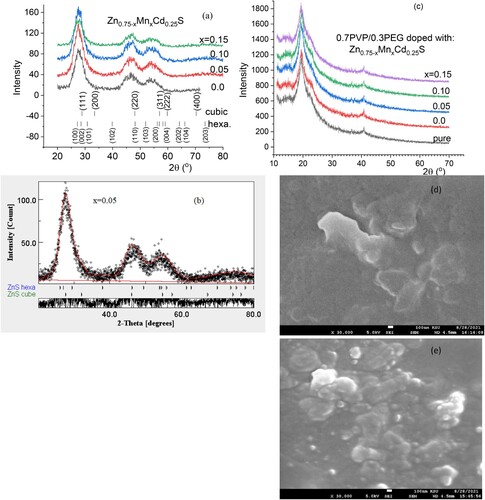
Table 1. Phase percentages, lattice parameters (Å), average crystallite size nm, and microstrain (ST×10−3) for the two phases in the nano filler Zn0.75−xMnxCd0.25S samples.
3.2. UV–Vis spectroscopy study
The wavelength-dependent of the absorbance and transmittance spectra of PVA/PEG (7:3) and Zn0.75−xMnxCd0.25S/PVA/PEG (7:3) blends are displayed in Figure . As revealed from Figure (a), the absorption of doped polymer samples is greater than the absorbance of the undoped ones. The absorption of the blend doped with Zn0.75Cd0.25S has the highest value except at higher wavelength value where sample with Mn content x = 0.1 has the highest absorption value. The improvement in the absorbance of the doped blend relative to the undoped one may be caused by the interaction of electromagnetic waves with the nanofiller and the electron in the blend. As displayed in Figure (b), the transmissions of different blends varied remarkably in the whole wavelength range. The fundamental absorption of the doped sample exhibited a redshift as the amount of manganese increased in the blend but irregularly, which pointed to the importance of Mn doping amount in Zn0.75Cd0.25S in form complexation between the blended polymer and the kind of the nanofiller. In the UV and visible range, the transmittance of the doped blends is smaller than that of the undoped blend. In the higher wavelength sample doped with 15%, Mn exhibited the highest transmittance. Figure (a) shows the variation of the extinction coefficient (k) for pristine PVA/PEG and doped by Zn0.75−xMnxCd0.25S with the wavelength. The k values of the doped blends are higher than the undoped one over the whole wavelength range, except the sample contained x = 0.15, it has less k value than all blended samples in the visible range. The k value was decreased as the content of Mn increased in the nanofiller (Zn0.75−xMnxCd0.25S). On the contrary, El-Desoky et al. found the k value of ZnS thin film was enhanced as it doped with La due to the improvement of the surface roughness [Citation29].
Figure 2. UV–vis (a) absorbance and (b) transmittance of Zn0.75−xMnxCd0.25S/PVA/PEG (7:3) blends.
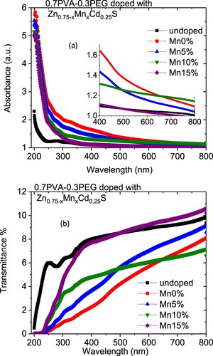
Figure 3. Variation of the (a) extinction coefficient and (b) refractive index for Zn0.75−xMnxCd0.25S/PVA/PEG (7:3) blends with wavelength.
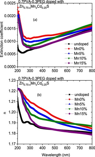
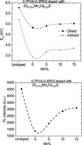
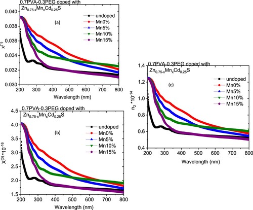
The variation in the k values in our case may be owing to a modification in the absorption process as the light interacted with a free carrier present in the different blends upon changing the amount of Mn [Citation30]. The wavelength dependence of refractive index (n) for doped and undoped blends are displayed in Figure (b). All blends exhibited a normal dispersion feature, where the refractive index reduced with an increase in the wavelength. The refractive indices of doped blends are higher than the undoped blend. Furthermore, the refractive decreased as the amount of Mn increased in the nanofiller. This reduction may be argued to be a reduction in the density of the doped blend because of the increase of the Mn content in the doped nanofiller connected with the main chain of the polymer blend. The direct or indirect optical band gaps can be extracted from the intercept of the linear segment of the relation between (αhν)2 or (αhν)0.5 and the photon energy (hν) with the hν axis (α = 0) (Figure a, b). From this figure, the direct and indirect optical bandgaps for the pristine PVA/PEG blend are 5.8 and 5.2 eV, respectively, which agrees with the results obtained previously [Citation31]. The direct and indirect optical bandgaps of the polymer blend were decreased from 5.78 to 4.83 eV and from 5.2 to 3.43 eV upon doping with Zn0.75Cd0.25S, respectively, and then increased a little by increasing the Mn content (x) (Figure c). The optical bandgap of the doped blend varies due to the changing of the crystallite size of the nanofillers (Table ) and hence changed the localized state created inside the optical bandgap, amount of defects and/or increase in the degree of disorder of the polymer [Citation32]. Similar result was found as the amount of Co increased in Zn1−xCoxO nanocrystalline thin films formed by the sol–gel and magnetron sputtering techniques [Citation33]. In addition, as Fe-doped ZnS thin film, the optical band gap reduced [Citation34]. Goktas et al. found that the optical band gap of ZnS thin film was reduced upon doping with Mn [Citation35]. They attributed the reduction to: (i) the possible formation of MnS in the ZnS matrix at higher Mn-doped amount, as MnS has a lower optical band gap than ZnS, (ii) the creation of the unsaturated chemical bonds between the atoms that might exist in the films for low Mn amount that create of some crystal defects, that can form localized states inside the band gap, (iii) and/or interacted the conduction and valence band electrons with the Mn2+ d electrons which caused the exchange interaction between the s-p band electrons and the Mn2+ electrons (sp-d exchange interaction) [Citation35]. This reduction in the optical bandgap increased the ability of the material to be applied in other optical applications. Figure shows changing of the real and imaginary parts (εr, εi) of dielectric constant with wavelength for all blends. The real part values of the dielectric constant have a similar trend as the refractive index while the imaginary part of the dielectric constant has a similar behaviour as the extinction coefficient (k). Furthermore, both εr and εi were increased as the PVA/PEG blend doped with nano Zn0.75−xMnxCd0.25S. In contrary to the results obtained from doped SnS thin film with indium [Citation36]. The values of εr and εi were decreased as the amount of Mn increased in the nanofiller. At a higher wavelength range blend doped with 10%Mn has the highest εr and εi values. The variations of VELF and SELF with wavelength for undoped and doped blends samples are displayed in Figure . As revealed from the graph both VELF and SELF exhibited a similar manner. Furthermore, the energy lost by electrons traveling in the material (VELF) is greater than the energy lost by electrons moving in the surface (SELF). Both VELF and SELF values were increased as the blend doped with the nanofillers. As the amount of Mn increased in the nanofillers, both VELF and SELF values decreased. Figure shows the changing of the optical conductivity (σopt) with the wavelength for all samples. The figure revealed that the optical conductivity was enhanced as the blend doped with nano Zn0.75−xMnxCd0.25S, and it decreased as the content of Mn increased in the nanofillers. This improvement may be caused by the formation of the new localized states inside the bandgap upon doping with the nanofillers which allowed the electrons to translate easily from the valence band to the nearest states and consequently the optical conductivity increased. The reduction in the optical conductivity upon increased the percentage of Mn in the nanofillers may be due to the variation of the crystallite size of the nanofiller (Table ). The variation of the linear optical susceptibility (χ(1)), third-order nonlinear susceptibility (χ(3)) and nonlinear optical refractive index (n2) with the wavelength for undoped and doped blended polymer are displayed in Figure . All parameters have a similar trend. All parameters were enhanced as PVA/PEG (7:3) blend doped with the nanofillers. As the amount of Mn increased in the nanofiller Zn0.75−xMnxCd0.25S, all parameters decreased. Therefore, the presence of nano Zn0.75−xMnxCd0.25S in polymer matrix allowed creation of serious free radical centres that reinforce the local polarization [Citation37]. The enhancement of nonlinear parameters as the blend doped especially with Zn0.75Cd0.25S nominated this blend to employ in various nonlinear optical and photonic fields.
Figure 4. Plots of (a) (αhν)2, (b) (αhν)0.5 vs. photon energy (hν) for Zn0.75−xMnxCd0.25S/PVA/PEG (7:3) blends and (c) the changing of the direct and indirect optical band gap values for different blends with the amount of Mn.
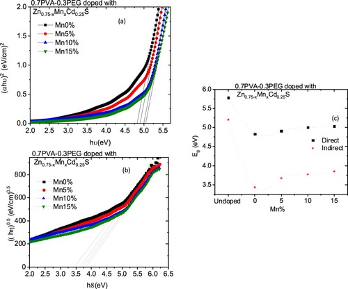
Figure 5. Variation of (a) real part and (b) imaginary parts of the dielectric constant for Zn0.75−xMnxCd0.25S/PVA/PEG (7:3) blends vs. wavelength.
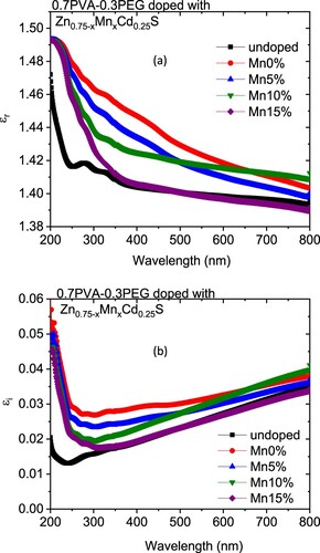
Figure 6. Variation of (a) SELF and (b) VELF vs. photon energy (hν) for Zn0.75−xMnxCd0.25S/PVA/PEG (7:3) blends with wavelength.
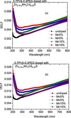
Figure 7. The wavelength dependence of the optical conductivity for Zn0.75−xMnxCd0.25S/PVA/PEG (7:3) blends.
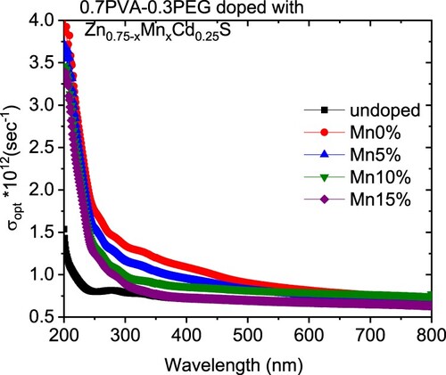
Figure 8. Changing of (a) the linear optical susceptibility, (b) the nonlinear third order of the optical susceptibility and (c) nonlinear refractive index for Zn0.75−xMnxCd0.25S/PVA/PEG (7:3) blends with wavelength.
3.3. Fluorescence (FL) investigation
Figure (a) shows the FL data at room temperature under excitation wavelengths of 380 nm for PVA/PEG (7:3) and Zn0.75−xMnxCd0.25S /PVA/PEG (7:3) blends. The FL intensity was decreased as the PVA/PEG (7:3) blend doped with nano Zn0.75−xMnxCd0.25S (Figure c–e). Furthermore, the FL intensity of the doped blends was enhanced as the amount of Mn increased in the nanofiller. The reduction of the FL intensity upon doping may result from the decreasing rate of recombination between the photo-induced electrons (e−) and holes (h+) pairs [Citation38, Citation39]. On the other hand, the enhancement of the FL intensity as the amount of Mn increased may result from the change in the number of non-radiative defects on the surface of the materials [Citation38]. According to the discussion mentioned in the UV part, Mn doping induced defects and sp-d exchange interaction which caused lattice damage in the Zn0.75Cd0.25S matrix [Citation35]. Therefore, the blend doped with Zn0.75−xMnxCd0.25S has less intensity than the undoped blend, and the intensity of all doped blend depends on the number of defects and the strength of sp-d exchange interaction in each dopant sample.
Figure 9. (a) The FL spectra for Zn0.75−xMnxCd0.25S/PVA/PEG (7:3) blends under 380 nm, (b) the Gaussian fitting for Zn0.65Mn0.1Cd0.25S blend sample and (c–e) changing of PL intensity Zn0.75−xMnxCd0.25S/PVA/PEG (7:3) blends with Mn amount.
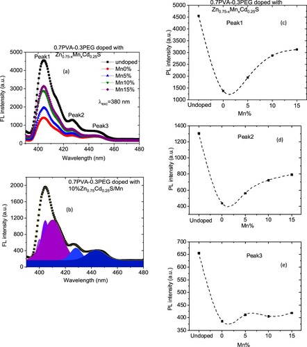
The FL data can be decomposed into sub spectra using Gaussian function into sub spectra (Figure b). All samples emitted three violets and two blue colours. The violet colour is caused by the transition of an electron from near band emission (NBE) and can be attributed to excitonic transitions [Citation40]. The blue colour is associated with defect-related luminescence [Citation40].
4. Conclusion
All Zn0.75−xMnxCd0.25S (x = 0.0, 0.5, 0.1, 0.15) nano samples exhibited biphasic ZnS phase structures; the major phase is cubic zincblende structure while the minor phase is hexagonal wurtzite structure. All blends exhibited a normal dispersion feature. The refractive indices of doped blends are higher than of the undoped blend. The refractive index decreased as the amount of Mn increased in the nanofiller. The reduction in the optical bandgap increased the ability of the material to be applied in other optical applications. The dielectric constant parameters, optical conductivity and nonlinear parameters were increased upon doping the PVA/PEG blend with nano Zn0.75−xMnxCd0.25S, but these parameters were decreased as the amount of Mn increased in the nanofiller. The decrease in the FL intensity as the blend doped with Zn0.75−xMnxCd0.25S nominates the doped blend particularly with x = 0.0 to be applied in photocatalytic degradation of different organic dyes.
Acknowledgment
This work is supported by Researchers Supporting Project number (RSP-2021/72), King Saud University, Riyadh, Saudi Arabia.
Disclosure statement
No potential conflict of interest was reported by the author(s).
Additional information
Funding
References
- Mallaiah Y, Jeedi VR, Swarnalatha R, et al. J Phys Chem Solids. 2021;155:110096.
- Toh HW, Toong DWY, Ng JCK, et al. Eur Polym J. 2021;146:110249.
- Polu AR, Kumar R. Chin J Polym Sci. 2013;31(4):641.
- Sofla MSK, Mortazavi S, Seyfi J. Carbohydr Poly. 2020;232:115784.
- Heiba ZK, Mohamed MB, Plaisier JR, et al. Chin J Phys 2020;67:414.
- Heiba ZK, Mohamed MB, Farag NM, et al. J Mater Sci Mater. 2020;31(15):12696.
- Heiba ZK, Mohamed MB, El Shimy H, et al. J. Mater. Sci. Mater. 2021;32(9):12358.
- Demirselcuk B, Kus E, Kucukarslan A, et al. Phys B. 2021;622:413353.
- Mohamed MB, Abdel-Kader MH. Mater Chem Phys. 2020;241:122285.
- Alhazime AA, Mohamed MB, Abdel-Kader MH. J Inorg Organomet Polym Mater. 2019;29(2):436.
- Mohamed MB, Heiba ZK, Imam NG. J Mol Struct. 2018;1163:442.
- Birhan D, Tekin D, Kiziltas H. Polym Bull. 2021. doi:10.1007/s00289-021-03914-4.
- Al-Azzawi ZM, Al-Baidhani M, Abed ARN, et al. Silicon. 2021. doi:10.1007/s12633-021-01325-8.
- Arandhara G, Mostako ATT, Dutta P, et al. Thin Solid Films. 2020;712:138317.
- Imam NG, Mohamed MB. J Mol Struct. 2016;1105:80.
- Goktas S, Goktas A. J Alloys Compd. 2021;863:158734.
- Jin H, Chen L, Liu A, et al. RSC Adv. 2016;6:28229.
- Heiba ZK, Mohamed MB, Plaisier JR, et al. Chin J Phys. 2020;67:414.
- Rodríguez-Carvajal J. Phys B (Amsterdam, Neth.). 1993;192:55.
- Lutterotti L. Nucl. Instrum. Methods Phys. Res. B. 2010;268:334.
- Al-Baradi AM, Altowairqi FA, Atta AA, et al. Chin Phys. B. 2020;29(8):080702.
- Tauc A. X. In: A Abeles, editor. The optical properties of solid. Amsterdam: North Holland; 1972. p. 277.
- Heiba ZK, Imam NG, Mohamed MB. Mater Sci Semicond Process. 2015;34:39.
- Heiba ZK, Mohamed MB, Imam NG. Alloys Compd. 2015;618:280.
- Goktas A, Modanl S, Tumbul A, et al. J Alloys Compd. 2022;893:162334.
- Tumbul A, Aslan F, Goktas A, et al. Mater Chem Phys. 2021;258:123997.
- Jayaramudu T, Raghavendra GM, Varaprasad K, et al. J Appl Polym Sci. 2016: 43027.
- Bhattacharyya R, Ray SK. Chem Eng J. 2015;260:269.
- El-Desoky MM, El-Barbary GA, El Refaey DE, et al. Optik (Stuttg). 2018;168:764.
- Tanaka K. Thin Solid Films. 1980;66:271.
- Mohamed MB, Abdel-Kader MH. Appl Phys A. 2019;125(3):1.
- Abdelghany AM, Abdelrazek EM, Rashad DS. Spectrochim Acta A Mol Biomol. 2014;130:302.
- Goktas A, Aslan F, Mutlu IH. J Alloys Compd. 2014;615:765.
- Goktas A. Appl Surf Sci. 2015;340:151.
- Göktaş A, Mutlu H. J Sol-Gel Sci Technol. 2014;69:120.
- Kafashan H. Ceram Int. 2019;45(1):334.
- Zhou P, You G, Li J, et al. Opt Express. 2005;13:1508.
- Heiba ZK, Mohamed MB, Imam NG. J. Supercond Nov Magn. 2017;30(11):3123.
- Raja G, Gopinath S, Azhagu R, et al. J Phys E. 2016;158:69.
- Imam NG, Mohamed MB. J Mol Struct. 2016;1105:80.