
 ?Mathematical formulae have been encoded as MathML and are displayed in this HTML version using MathJax in order to improve their display. Uncheck the box to turn MathJax off. This feature requires Javascript. Click on a formula to zoom.
ABSTRACT
Electrochemical water splitting is a well-sought method for the production of renewable energy due to its low cost, high efficiency, ease of operation, availability of a variety of catalysts, and green approach. In this research, an amine-functionalized Ce-MOF loaded on nickel foam (NF) presented as Ce-MOF-NH2/NF electrocatalyst is prepared by a simple hydrothermal method. Prepared material is characterized by X-ray diffraction (XRD), energy-dispersive spectroscopy (EDS), Fourier transform infrared spectroscopy (FTIR), scanning electron microscopy (SEM), and atomic force microscopy (AFM) to confirm morphological and structural properties. The synthesized catalyst is used for electrochemical OER in a 1M KOH solution. Ce-MOF-NH2/NF demonstrated onset potential, Tafel slope, and overpotential of 1.49 V, 69 mV/dec, and 328 mV, respectively. For comparison, Ce-MOF is also prepared and employed for OER under the same conditions and it exhibited onset potential, Tafel slope, and overpotential 1.5 V, 89 mV/dec, and 348 mV, indicating the superior performance of functionalized MOF. The obtained results reveal the promising overpotential of the Ce-MOF-NH2/NF -based electrocatalyst for green energy production via electrochemical water splitting.
1. Introduction
Over the past three decades, people have faced three challenges, such as the energy crisis, rapidly changing climatic conditions, and the economic crisis, and all of these problems are interconnected with each other [Citation1]. To meet their energy needs people used fossil fuels, but they were unaware of the fossil fuel shortage and its harmful effects on the environment. Energy efficiency is also important to reduce the negative impact of climate change. Metal ion contamination, causing damage and disease to humans and other living organisms, has become a serious environmental problem [Citation2]. The growing energy crisis and pollution from fossil fuels have motivated researchers to generate energy from sustainable energy sources. The most popular renewable energy sources are solar power, wind power, tidal power, geothermal power, biomass power, and hydropower. Renewable energy sources can produce electricity with less environmental impact than traditional fuels, but they have some disadvantages [Citation3,Citation4].
With the increasing demand of the candidates, non-renewable energy sources are being depleted making it necessary to develop alternative sources of energy that esteem the surroundings to solve environmental problems and energy shortages caused by the reduction of fossil fuels. Much attention is paid to hydrogen, highly efficient, carbon-free, sustainable, and environmental friendly, and can be obtained by electrocatalytic water splitting [Citation5,Citation6]. Water electrolysis has proven to be one of the cleanest and cheapest methods for producing hydrogen. Mostly two methods i.e. photochemical and electrochemical are used for this purpose. Among them, the photochemical process is not much efficient as that the electrochemical process due to regional variability of the sunlught. Electrochemical oxidation and reduction reactions offer a promising foundation for renewable energy storage [Citation7]. Redox reactions between water, oxygen, and hydrogen have received increased attention in the last few years due to their role in various energy processes but OER is a kinetically sluggish reaction [Citation8]. For their practical application, due to the high natural kinetic barriers, a highly active, inexpensive, and efficient electrocatalyst for OER and HER is required to reduce activation energy and improve the energy process. Commonly used catalysts for OER are noble metals and their compounds such as Pt for HER and IrO2 for OER [Citation9]. These noble metals are not only precious but also rare on earth. However, their low stability, high cost, and shortage have excluded electrocatalysts based on noble metals from the widespread introduction of electrochemical energy technologies [Citation10,Citation11]. Enormous efforts have been devoted to providing efficient, earth-abundant, and durable electrocatalysts for water splitting. Transition metals such as Fe, Ni, Co, Zn, etc. have the advantage of being inexpensive, non-toxic, and common on earth, but they exhibit high overvoltage and poor stability during water splitting [Citation12–14]. Therefore, the development of a stable and inexpensive electrocatalyst with efficient performance is a key step toward the practical application of renewable electrochemical energy technologies.
Several catalysts, other than noble metals have been used during the past few years such as oxides, hydroxides, oxyhydroxides, nitrides, sulphides, selenides, and phosphates of transition metals which showed high performance for OER in alkaline media [Citation15]. Many electrocatalysts for OER have also been used, such as carbides, chalcogenides, and phosphides of transition metals showing high performance in alkaline media. So, the activity and stability of low-cost transition metal-based electrocatalyst remain to be improved [Citation16].
In recent years, organic metal frameworks (MOFs) containing metal cations and organic linkers have been used as the main electrocatalyst for HER and OER to solve the above problems [Citation17]. Three-dimensional MOFs are porous crystalline nanostructures consisting of a regular arrangement of metal cations surrounded by bi- or polydentate ligands (and negatively charged molecules) [Citation18,Citation19]. MOFs have been used for CO2 reduction, organic pollutant degradation, water splitting, adsorption, catalysis, and sensing. MOFs are used as catalysts, especially in energy catalysts because of their uniform ordered porosity, large internal surface area, diversity in metals and functional groups, tunable structure, and easy synthesis without surfactant, which are propitious for highly efficient electrocatalytic progress [Citation20]. In electrocatalysis, high performance has been shown in different MOFs such as zeolitic imidazolate, Prussian blue analogues, carboxylate-based MOFs, and porphyrin-based MOFs. The most outstanding advantage is the physical and chemical properties of MOFs, further enhanced by designing the composition and structure. Recently many papers related to MOFs as electrocatalysts for water splitting have been reported[Citation21–23]. These works showed the rapid use of MOFs in electrocatalytic water splitting. On the other hand, Metal-organic frameworks (MOFs) are a class of nanoporous semiconductors used in a variety of applications. MOFs with interconnected pores and intra-framework chemical activity are interesting for a range of electrocatalytic and electrochemical water splitting applications because of their high density and spatially segregated active sites. MOFs containing lanthanide core metals exhibit a broad range of structural heterogeneity due to their varying coordination numbers (between 6 and 12), ionic radius, coordination geometries, and variety of organic ligands used in their synthesis. In addition, rare earth metals like cerium, praseodymium, and neodymium are ideal replacements for heavy and dangerous cations like zinc cations, which are ecologically friendly metal cations. Hence, the advent of group 4 metal-based MOFs, which are particularly stable in aqueous solutions, has sparked a renewed interest in aqueous electrochemical systems, because during electrochemical processes, redox hopping may be used to move charges inside group 4 metal-based MOF frameworks. Hence, several groups have looked at hopping-based charge transfer in different Zr-based MOFs containing redox-active moieties, including ourselves. Among all, MOFs based on Ce(III) cations are becoming increasingly popular due to their widespread availability and low manufacturing costs. The uncoordinated Ce(IV) sites found in the nodes of a Ce-MOF shown to execute node to node charge hopping and a reversible Faradaic response in aqueous electrolytes. Therefore, electrocatalysis on Ce-MOFs has gotten little attention. Secondly, cerium is a highly conducting metal and it forms stable coordination bonds with carboxylic groups of the ligands, forming 3D MOFs. However, the functionalization in MOFs for further improvement in electrocatalytic water splitting applications is needed to be clarified [Citation24,Citation25].
In this study, Material is characterized by different characterization techniques and applied for water splitting in 1M KOH solution. For comparison, Ce-MOF/NF is also prepared and water splitting experiments are carried out under the same experimental conditions. The obtained outcomes are discussed below.
2. Experimental
2.1 Chemicals
1,4-benzene dicarboxylic acid, acetone, cerium nitrate hexahydrate, potassium hydroxide, dimethylformamide, ethanol, and 2-amino-1,4-benzenedicarbylic acid, were provided by Sigma Aldrich, USA. Deionized water was obtained from a local deionizer plant. All the chemicals were of analytical grade and used without any further pretreatment.
2.2 Synthesis of metal-organic framework
MOFs were synthesized by a modified solvothermal process [Citation26]. 1,4-benzene dicarboxylic acid (0.25 mmol for 1) or 2-amino-1,4-benzenedicarbylic acid (0.25 mmol, for 2) was added to DMF (5 mL). The solution was stirred to obtain a clear solution. Then, cerium nitrate hexahydrate (0.5 mmol) was added and stirred at 120°C for 10 min, and then the resulting clear solution was transferred to a Teflon-lined reaction vessel. The autoclave was put into the oven at 120°C for 24 hours. The obtained crystalline material was cooled to room temperature, washed with DMF, and dried at room temperature overnight. The material was then characterized and used as a catalyst for OER.
2.3 Characterization
The crystalline structures of prepared MOFs were investigated by Powder X-ray Diffraction (XRD) using Bruker Diffractometer (D8-advance) equipped with a Cu-Kα radiation source. To interpret the morphology of MOFs, a Scanning Electron Microscope (JSM5910). An energy dispersive spectrometer (JSM5910) was used for elemental analysis. The surface area and porosity of synthesized MOFs were investigated by Brunauer–Emmett–Teller (BET) using NOVA2200e. To obtain Fourier transform infrared (FT-IR), Nicolet spectrometer 170SXFTIR (400–4000 cm−1) was used.
2.4 Pre-treatment of nickel foam (NF)
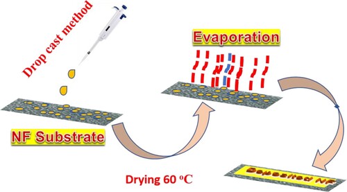
In a representative 3-electrode system, working electrode, reference (Ag/AgCl), and counter electrode (Pt-wire) were employed for electrochemical performance. In this case, working electrode NF deposited with prepared MOFs was used. For this purpose, substrate (NF) is pierced into 1 × 1 cm small pieces. These small pieces were sonicated firstly in acetone (C3H6O), HCl (2M), water, and ethanol (C2H5OH) for 20 min, respectively. Then these small NF pieces were dried at 60°C in an oven for 25 min. For the electrochemical studies of fabricated materials, the already synthesized material (1.5 mg) was first crushed into fine powder finally and then mixed with DI water (100 µL). To obtain the homogenous catalyst ink, the solution was sonicated for 0.5 hours, and to deposit synthesized catalyst ink onto dried and cleaned NF, a drop-casting method was used. The synthesized catalyst ink (10 µL) was deposited on the NF surface and then dried in air overnight. The loaded and dried NF small pieces were used for further electrochemical measurements ().
Scheme 1. Schematic illustration of electrode preparation.
2.5 Electrochemical studies
The electrochemical behaviour of the material was studied on a PGSTAT 204 (computer-controlled potentiostat AUTO LAB). It consisted of a characteristic 3-electrode system suspended vertically in a glass cell (Teflon lined). To study the OER applications of the synthesized material 3-electrode system was used. Firstly, the electrochemical cell was cleaned by boiling with a solution of H2SO4 and HNO3 with a volume ratio of 1:3, followed by de-ionized water. Finally, cleaned it many times with de-ionized water and acetone, respectively, and dried it at 80 oC in an oven. The Pt-wire acting as the counter electrode was washed with DI water and then immersed in a 20% solution of HNO3 for 5 min. The reference electrode was silver–silver chloride (Ag/AgCl) with a 3M KCl saturated solution. OER measurements were carried out at room temperature in 1.0M KOH solution (pH 13.6). The CV measurements were employed at the positive and negative potentials at the scan rate of 10.0mVs −1. In this case, the dipped NF surface area was considered mostly (0.5cm2). The resultant potential (vs. Ag/AgCl) was converted to the potential of RHE, according to the following Equation (1) [Citation27].
(1)
(1)
In the above relation, the potential vs. RHE are represented by ERHE. The reference electrode (Ag/AgCl) potential is represented by EAg/AgCl. The correction factor is 0.059; pH shows the pH of electrolyte. EoAg/AgCl represents the standard potential of Ag/AgCl which is equal to 0.197.
2.6 Kinetic mechanism of the OER
The electrocatalytic mechanism depends on its catalytic activity and good catalysts are highly efficient in the description of the established mechanism. So, catalytic activity and kinetics of prepared MOFs were determined and the equation used to calculate the overpotential is [Citation28]:
(2)
(2)
Where is overpotential, n is the number of electrons involved in the reaction mechanism, α shows the charge transfer coefficient, j represents the current density and F shows the Faraday constant.
2.7 Turnover frequency (TOF)
Turnover frequency (TOF) represents the power of catalysts to change reactants into products in unit time under given conditions. TOF of the prepared MOF is determined by the following equation [Citation28].
(3)
(3)
In this equation, I is the measured current (A), F indicates the Faraday’s constant, and m represents the number of moles of the catalyst.
2.8 Electrochemical active surface area (ECSA)
The small potential range (0–0.1 V) was studied for the cyclic voltammogram curve. The CV data was studied at different scan rates. The change in current density was determined from the cathodic and anodic current values and these values were plotted versus applied scan rates to get a straight line. Double-layer capacitance (Cdl) was obtained by dividing the slope of the line by 2 and the value of ECSA was determined by dividing Cdl by specific capacitance (∼ 0.040 mFcm−2)
2.9 Electrochemical impedance spectroscopy
Determining the resistivity and conductivity of material under observation is an important parameter. For this solution resistance (Rs) and charge transfer resistance (Rct) of the electrode/electrolyte interface were investigated. The EIS was studied by using an electrochemical workstation (Metrohm Autolab) at the potential applied of 0.5 V, the amplitude of 0.01 VRMS, and the frequency range of 1 × 10⁻⁵–0.1 Hz. The values of Rct and Rs were obtained by manipulating the randles circuit. Lower values of Rct showed faster electron transfer and high conductivity of the material.
2.10 Chronoamperometry
A good catalyst must have higher activity as well as greater stability. Its high stability and durability make it suitable for replacing the expensive catalyst. Chronoamperometry was used to determine the stability of the material. It was carried out at 0.8 V for 40 hrs.
3. Results and discussion
3.1 Characterization of Ce-MOF and Ce-MOF-NH2
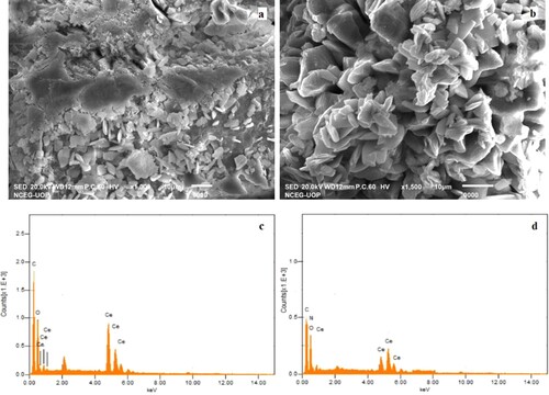
SEM images of synthesized MOF catalysts are shown in Figure (a) and (b). SEM images show irregular geometry of Ce-MOF/NF particles with particle sizes around 80–120 nm (Figure (a)). In Ce-MOF/NF, some particles are agglomerated which may be due to the improper sample preparation during SEM analysis. On the other, Ce-MOF-NH2/NF most of the crystals are well dispersed but some of them are agglomerated due to hydrogen bonding (Figure (b)). Energy-dispersive spectroscopy (EDS) analyses of Ce-MOF/NF and Ce-MOF-NH2/NF are given in Figure (a) and (d), respectively. EDS is done to access the elemental composition of the MOFs. EDS analysis of Ce-MOF/NF shows carbon, oxygen, and cerium are present at the atomic percent of 54%, 29%, and 16%, respectively. While in the case of Ce-MOF-NH2/NF, carbon (41%), nitrogen (17%), oxygen (19%), and cerium (23%) are present at their respective positions. These results indicate the successful formation of MOFs with each element present at their appropriate ratios.
Figure 1. Scanning electron microscopy images of (a) Ce-MOF and (b) Ce-MOF-NH2 and EDS spectrum of (c) Ce-MOF/ NF and (d) Ce-MOF-NH2/ NF.
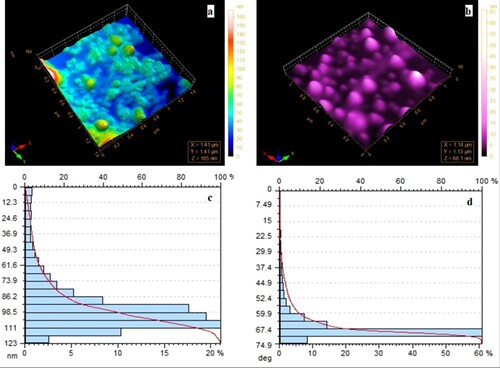
Atomic force microscopy (AFM) analysis of synthesized MOFs is carried out to access the surface topology. AFM images show smooth surfaces of the particles with different morphology. Ce-MOF-NH2/NF shows a more smooth surface than Ce-MOF/NF, associated with the presence of amine functional groups on the ligand. AFM images and particle size distribution of both materials are shown in Figure which shows that the particle size of Ce-MOF is around 150 nm while the particle size of Ce-MOF-NH2/ NF is 80 nm. These results are complementary to the SEM results of both materials.
Figure 2. Atomic force microscopy images of (a) Ce-MOF/NF and (b) Ce-MOF-NH2NF and particle size distribution of (c) Ce-MOF/NF and (d) Ce-MOF-NH2/NF.
XRD spectrum of the synthesized MOFs is shown in Figure (a). XRD spectrum is recorded in the 2 theta range of 10° to 70°. XRD spectrum of Ce-MOF/NF shows sharp peak patterns which indicate that synthesized material is crystalline. Peaks at 2 theta ranges of 13°, 16°, 18°, 21°, 24°, 28.3°, 33°, 47.4°, 56.4°, and 59° are observed which are consistent with previously reported literature [Citation29]. These peaks indicate the crystalline structure of Ce-MOF/NF. A similar peak pattern is observed for Ce-MOF-NH2/NF but peaks are much sharper and have higher intensities which indicate higher crystallinity of the material. The crystallite size of the materials is determined by the Scherrer equation and the obtained crystallite size of the composite is 27.3 nm.
Figure 3. (a) XRD and (b) FTIR of Ce-MOF/ NF and Ce-MOF-NH2/ NF.
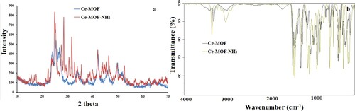
FTIR analysis of as-synthesized MOF-based catalysts is shown in Figure (b). For Ce-MOF/NF, a peak located at 3300–3400 cm−1 is due to O-H stretching, indicating physically adsorbed water molecules. IR peaks appearing in the regions 1611–1555 cm−1 and 1434–1370 cm−1 are attributed to the carboxylate ions (-COO). IR band at 500–700 cm−1 is attributed to the Ce-O stretching vibration. However, in Ce-MOF-NH2/NF, although peak pattern is quite similar with a slight difference due to the presence of -NH2. An additional peak is around 3400 cm−1 is attributed to amine groups. stretching vibrations Ce-O appeared in the range of 500–700 cm−1. These results demonstrate the successful formation of MOFs.
3.2 Electrochemical water splitting by Ce-MOF/NF and Ce-MOF-NH2/NF
The electrochemical activity of Ce-MOF/NF and Ce-MOF-NH2/NF were evaluated in 1.0M KOH solution at room temperature via Metrohm Autolab-204. The comparison of the electrocatalytic activities of different electrode bare NF, Ce-MOF/NF, and Ce-MOF-NH2/ NF was shown in Figure (a–d). In the CV and LSV curves (Figure (a–b)) the anodic peak occurs at 1.4 V vs. RHE can be seen, this peak is due to the anodic oxidation of Ni-based species (NF). To estimate the performance of OER and restrict the overlapping of OER current with oxidation current, 10mAcm−2 was selected. In this case, the Ce-MOF-NH2 /NF displays better electrocatalytic performance than another candidate. The current density, onset potential, and overpotential values of bare NF, Ce-MOF/ NF, and Ce-MOF-NH2/ NF were presented in Table . It is noted that the overpotential of Ce-MOF-NH2/ NF is lower as compared to Ce-MOF/ NF. This is due to the addition of ABDC resulting in strong interactions with Ce metal. However, strong interactions of ABDC with Ce metal, highly porous nature, compact morphology, and conductive NF allow the rapid transport of electrons for OER and boost the electrolyte to diffuse and penetrate inside the pores.
Figure 4. (a) CV, (b) LSV, (c) Tafel slope, and (d) electrochemical impedance spectroscopy of bare NF, Ce-MOF/NF, and Ce-MOF-NH2/NF, respectively.
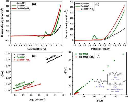
Table 1. Comparative study for all synthesized electrodes.
The Tafel analysis determines the kinetics of the electrocatalysts it is inversely related to the charge transfer coefficient. When the Tafel slope value becomes smaller, a faster charge transfer process starts at the electrocatalytic interface as shown in Figure (c). So one can measure the electron transfer number during the rate-determining step for oxygen evolution reaction and determine the mechanism. The resultant Tafel slope for all the fabricated electrodes is tabulated in Table . The mechanism of the material for different electrocatalytic reactions has been discussed below. In the 1st step, it is usually noted that Ce-based electrocatalysts have three intermediate steps during oxygen evolution reaction and the related mechanism is explained in Equations (4)–(7)
(4)
(4)
(5)
(5)
(6)
(6)
(7)
(7)
(8)
(8)
(9)
(9)
In the above steps, both (4) and (5) are highly reversible reactions, on the other hand, step (3) is slowest and irreversible. This slowest step controls the overall rate of the whole process occurring in the electrochemical cell and the electrocatalysts usually facilitate the kinetics of the 3rd step. In the anodic oxygen evolution reaction process, Ce-O inside the metal–organic framework was oxidized into Ce(OH)4 species acting as active centres, facilitating the oxidation of hydroxyl groups forming oxygen molecules.
Additionally, ionic and charge transport resistance (Rct) are essential factors because they affect the reaction barrier of the OER. The improved electrical conductivity of the synthesized material was explored by electrochemical impedance spectroscopy (EIS) as shown in Figure (d). Rct value is ascribed to the semicircles in the region (high frequency) as shown in the Nyquist plot (Figure (d)). The charge transfer resistance of all the synthesized materials is charted in Table . The lower Rct value of the functionalized MOF confirms the fast electron transfer rate that is associated with the kinetics of the electrocatalyst. For the charge transfer resistance, the Randles circuit is fitted to attain the value of both the catalysts and the Nyquist plot for the simplified Randles circuit is always a semicircle.
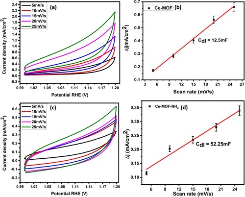
To gain more about OER catalytic performance, ECSA is another important factor to evaluate the activity of synthesized electrocatalyst which shows direct relation to the double-layer capacitance (Cdl). The greater value of Cdl showed the larger ECSA that can be measured by the cyclic voltammograms (CV). CV curves of the designed material are measured in the non-faradic region (no charge transfer) at a different scan rate. However, a large surface area of electrocatalyst provided the more active sites which promote the adsorption of H2O molecules to make it favourable for best OER electrocatalytic activity. Ce-MOF-NH2/NF showed a higher value of Cdl 52.25 µF with ECSA value (1306cm2) which provided the more active sites to electrolyte and catalyst interface for better OER performance as compared to Ce-MOF/ NF(12.5µF) with ECSA (306.25cm2) as displayed in Figure (a–d).
Figure 5. (a) non-faradic CV curves at different scan rates, (b) double-layer capacitance calculated via delj vs. scan rate of Ce-MOF/NF, (c) non-faradic CV curves at different scan rates, (d) double-layer capacitance calculated via delj vs. scan rate of Ce-MOF-NH2/NF, respectively.
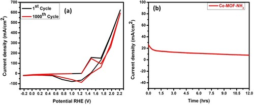
Furthermore, the stability of the catalyst Ce-MOF-NH2/NF was tested by using CV scanning 1000 cycles and a long-term Chronoamperometric curve Figure (a, b). The CV curves shown in (Figure (a)), show a slight change between the 1st and 1000th cycles, and a slight decrease in current density after 12 hours (Figure (b)). As we know, the conductivity of the electrocatalyst is due to the electron transfer capacity of the OER and kinetic process. As compared to carbon materials, MOF-based electrocatalysts improve conductivity as well as allow higher dispersion, and provide additional metal centres to become electrochemically accessible. Hence improving the durability of Ce-MOF-NH2/NF catalyst in alkaline solution (1.0M).
Figure 6. (a) Comparison of 1st and 1000th CV cycle, (b) Chronoamperometry curve of Ce-MOF-NH2/NF, respectively.
A detailed comparison of the OER performance of several other reported materials is given in Table .
Table 2. Electrochemical performance comparison of Ce-MOF-NH2/NF with other reported materials.
4. Conclusion
In this research, cerium MOF-based electrocatalysts are synthesized and used for OER. Ce-MOF-NH2/NF and Ce-MOF/NF are synthesized by a single-step hydrothermal growth process. Morphology, size, crystal structure, elemental composition, and functional group analysis are done by SEM, EDS, AFM, XRD, and FTIR. The prepared catalysts showed promising electrocatalytic activities in 1M KOH solution. Ce-MOF-NH2/NF demonstrated onset potential, Tafel slope, and overpotential of 1.49 V, 69 mV/dec, and 328 mV, respectively. For comparison, Ce-MOF/NF is also prepared and applied for electrochemical water splitting under the same conditions and it exhibited onset potential, Tafel slope, and overpotential of 1.5 V, 89 mV/dec, and 348 mV. Ce-MOF-NH2/NF showed better electrochemical water splitting efficiency than Ce-MOF/NF. Better electrochemical performance could be attributed to the presence of amine groups at the MOF surface, facilitating the charge-transfer phenomenon. The efficiency of the catalyst is compared with other reported materials.
Acknowledgment
We would like to thank Taif University Research Supporting Project number (TURSP-2020/63), Taif University, Taif, Saudi Arabia. Moreover, the authors extend their appreciation to the Deanship of Scientific Research at King Khalid University, Saudi Arabia for funding this work through Research Groups Program under grant number R.G.P2/171/43.This work was supported by Bahauddin Zakariya University: [Grant Number R&D545].
Disclosure statement
No potential conflict of interest was reported by the author(s).
Additional information
Funding
References
- Reddy CV, Reddy KR, Shetti NP, et al. Int J Hydrogen Energy. 2020;45:18331–18347.
- Rehman A, Rauf A, Ahmad M, et al. Environ Sci Pollut Res. 2019;26:21760–21773.
- Gielen D, Boshell F, Saygin D, et al. Energy Strat Rev. 2019;24:38–50.
- Güney T. Int J Sust Dev World Ecol. 2019;26:389–397.
- Ng KH, Yuan LS, Cheng CK, et al. Chem Eng J. 2021;128847.
- Wang Z, Li C, Domen K. Chem Soc Rev. 2019;48:2109–2125.
- Inamdar AI, Chavan HS, Jo Y, et al. Int J Energy Res. 2021.
- Wang Q, Domen K. Chem Rev. 2019;120:919–985.
- Li L, Wang B, Zhang G, et al. Adv Energy Mater. 2020;10:2001600.
- Li Y, Sun Y, Qin Y, et al. Adv Energy Mater. 2020;10:1903120.
- Zou X, Zhang Y. Chem Soc Rev. 2015;44:5148–5180.
- Du X, Li J, Tong K, et al. Dalton Trans. 2021;50:6650–6658.
- Wang F, Shifa TA, Zhan X, et al. Nanoscale. 2015;7:19764–19788.
- Guo Y, Park T, Yi JW, et al. Adv Mater. 2019;31:1807134.
- Lyu F, Wang Q, Choi SM, et al. Small. 2019;15:1804201.
- Anantharaj S, Aravindan V. Adv Energy Mater. 2020;10:1902666.
- Wang W, Xu X, Zhou W, et al. Advanced Science. 2017;4:1600371.
- Luo H, Zeng Z, Zeng G, et al. Chem Eng J. 2020;383:123196.
- Ali M, Pervaiz E, Noor T, et al. Int J Energy Res. 2021;45:1190–1226.
- Song F, Li W, Sun Y. Inorganics. 2017;5:40.
- Zhou J, Dou Y, Wu XQ, et al. Small. 2020;16:1906564.
- Xu X, Wang T, Zhao C, et al. Microporous Mesoporous Mater. 2021;312:110760.
- Liu T, Li P, Yao N, et al. Adv Mater. 2019;31:1806672.
- Srinivas K, Chen Y, Wang X, et al. ACS Sustain Chem Eng. 2021;9:1920–1931.
- Zhang H, Su J, Zhao K, et al. ChemElectroChem. 2020;7:1805–1824.
- Karimi M, Mohebali H, Sadeghi S, et al. Microporous Mesoporous Mater. 2021;322:111054.
- Sadaqat M, Nisar L, Hussain F, et al. J Mater Chem A. 2019;7:26410–26420.
- Sadaqat M, Manzoor S, Nisar L, et al. Electrochim Acta. 2021;371:137830.
- Xiong Y, Chen S, Ye F, et al. Chem Commun. 2015;51:4635–4638.
- Huang D-D, Li S, Wu Y-P, et al. Chem Commun. 2019;55:4570–4573.
- Khalid M, Hassan A, Honorato AM, et al. Chem Commun. 2018;54:11048–11051.
- Huang X, Yao H, Cui Y, et al. ACS Appl Mater Interfaces. 2017;9:40752–40759.
- Tian J-W, Fu M-X, Huang D-D, et al. Inorg Chem Commun. 2018;95:73–77.
- Rui K, Zhao G, Lao M, et al. Nano Lett. 2019;19:8447–8453.
- Huang H, Zhao Y, Bai Y, et al. Adv Sci. 2020;7:2000012.
- Zhou W, Wu Y-P, Wang X, et al. Cryst Eng Comm. 2018;20:4804–4809.
- Liu T, Li P, Yao N, et al. Angew Chem. 2019;131:4727–4732.
- Zhu D, Liu J, Zhao Y, et al. Small. 2019;15:1805511.
- Ai L, Luo Y, Huang W, et al. Int J Hydrogen Energy. 2022;47:12893–12902.
- Huang N, Chen Y, Liang Y. J Mol Struct. 2022;1257:132586.
- Taherinia D, Moravvej S, Moazzeni M, et al. Sust Energy Fuel. 2021;5:2994–3000.
- Taherinia D, Moazzeni M, Moravej S. Int J Hydrogen Energy. 2022.