
 ?Mathematical formulae have been encoded as MathML and are displayed in this HTML version using MathJax in order to improve their display. Uncheck the box to turn MathJax off. This feature requires Javascript. Click on a formula to zoom.
ABSTRACT
The theme of this work is to examine the magnetized flow behaviour of hybrid nanofluid containing molybdenum disulphide (MoS2) and graphene oxide (GO) nanoparticles subject to multiple slip mechanisms, natural convection and chemical reaction of mth order. The working hybrid nanofluid is prepared by an amalgamation of nanoparticles, i.e. MoS2 and GO and conventional fluid (H2O). The existing equations of the model were solved by the techniques, i.e. shooting and bvp4c. To validate our codes, the comparison was presented by previous research. Here, we observed that, with an increase in thermal slip parameter values, only the thermal field profiles of MoS2–GO/H2O regularly depreciated. Moreover, when there was augmentation in velocity slip parameter, temperature and concentration functions rose, while both velocity outlines of MoS2–GO/H2O fluid declined. Furthermore, the velocity functions of MoS2–GO/H2O augmented and the concentration function declined with an increase in natural convection parameter values.
1. Introduction
In the present era of industry 4.0, several industrial applications require the instantaneous control of heat and mass transport phenomena for well productivity of the machines. Cooling becomes an important part in this aspect. For example, condensed solar cell in the solar panel must be cooled properly for better efficiency and long life. In fuel cells, the chemical energy of the controlled combustion of fuel is transformed into other forms of energy. This further assists in operating the industrial machinery, and simultaneously cooling the machine during the operation. Apart from these, the controlled heat and mass transfer (HMT) flows are also encountered in the use of natural energy resources like biomass, wind, hydro and solar power, etc. The study of enhanced HMT also acting a dynamic role in improved health and a pollution-free environment. These types of studies help in the prediction of the risk of environmental contamination by chemical or biological agents. In advanced drug delivery devices, the cooling or heating must be controlled and optimized to prevent the body cell damage during the drug delivery.
Considering the vast significance of simultaneous HMT, in the past few decades, many researchers have studied these flows under various circumstances. Siddheshwar and Mahabaleswar [Citation1] studied the magnetohydrodynamic HMT flow of visco-elastic fluid past a stretching sheet due to some heat source. The analytical results of flow due to stretching sheet were found by Vajravelu and Canon [Citation2]. Cortell [Citation3] deliberated the heat and mass features of flow over a nonlinearly stretching sheet considering the nonlinear radiation effect. Rashidi et al. [Citation4] probed the free convective flow of working fluid due to sheet with temperature and concentration differences and established the semi-analytic solution of the formulated problem by using homotopy analysis method (HAM). Muhammad et al. [Citation5] analysed the three-dimensional HMT flow over an exponentially stretching sheet, considering the dissipation effect.
With the development of machinery in the industry 4.0 era, the claim for better cooling systems with enhanced accuracy and consistency has augmented. The designs of the cooling systems are becoming compact day by day. To augment heat transfer rate (HTR), the designs of the devices have to be relooked, but due to several scientific constraints this is not actually very feasible. Therefore, the alternate way out for this problem is to use a coolant with high thermal properties. It has been studied that the insertion of a small percentage of nano-sized particles of metal or their oxides into the pure fluid enhances the thermal conductivity of these pure fluids by significant amounts. These fluids are called nanofluids. Due to the enhanced thermophysical possessions of nanofluids, researchers in the field of HMT included nanofluids in their studies. Khan and Pop [Citation6] inspected the HMT flow of a nanofluid past a stretching sheet. Hayat et al. [Citation7] discovered the three-dimensional flow of alumina-H2O nanofluid over a stretching sheet and investigated the nonlinear radiation effect and computed the solution for the formulated problem. A finite element study of natural convection of H2O-based alumina nanofluid was done by Sheikholeslami et al. [Citation8]. They investigated the flow in a two-dimensional square cavity with a heat source placed centrally at one of the walls. Hayat et al. [Citation9,Citation10] found the semi-analytic solution of the 3D flow of working fluid due to exponentially stretching and bidirectional nonlinear stretched sheets by HAM. The flow was analysed under fixed mass and heat fluxes. Mahanthesh et al. [Citation11] performed a comparative study of three different H2O-based nanofluids with respect to the 3D flow. This study comprised both linearly and nonlinearly stretching sheets. Furthermore, Reddy and Chamkha [Citation12] found the impact of chemical reaction (CR) in the HMT flow of H2O-alumina nanofluid. The nonlinear radiation approximation was considered in the study. Mousa et al. [Citation13] completed the solution of the heat transfer problem by the combined method MOL-PACT. Bhatti et al. [Citation14] implemented a perturbation technique for the results of visco-elastic fluid flow in a channel.
After the finding of nanofluids and their superior thermal properties, nanofluid has received an important consideration over the earlier two decades. As mentioned above, many theoretical and experimental studies have shown nanofluids to be a good resource for improved heat transfer rates. After these successful studies, the researchers have also tried to further enhance the stability, thermal and physical properties of fluids and came up with the idea of synthesizing the fluids by inserting the two or more nanoparticles of different nature in the base fluid directly or in the form of composites and named this new category of fluids as hybrid nanofluids. In the last decade, many studies have shown that the properly hybridized nanofluids may show promising results with respect to the improved HTR. Iqbal et al. [Citation15] explored the nanoparticle shape effect on the flow of H2O-based molybdenum disulphide (MoS2) and silica hybrid nanofluid over the curved stretching surface. They reported that hybrid nanofluid has better low rates as compared to silica-H2O nanofluid. Notifying the better thermal conductivity and very high boiling point the flow of propylene glycol-based MoS2 and silica hybrid nanofluid was deliberated by Shaiq et al. [Citation16]. An experimental study on the sesame oil-based carbon nanotube (CNT)/ MoS2 nanofluid was accomplished by Gugulothu and Pasam [Citation17]. Khashi’ie et al. [Citation18] probed the 3D flow of Cu-alumina-H2O hybrid nanofluid due to its permeable surface. They reported the existence of a dual solution for the considered configuration and found one stable and another unstable solution. Very recently, a comparative study for the mixed convection of hybrid nanofluid with water and multi-walled CNTs-Cu, CNT-water and pure water was performed by Muhammad et al. [Citation19].
After the ground breaking discovery of graphene by the Nobel laureates Geim and Novoselov [Citation20], a new fertile ground has opened up for tremendous industrial applications. Researchers have proved that graphene is the lightest material with the highest thermal transport properties even at room temperature [Citation21,Citation22]. Apart from these properties of graphene, this material is also known to be a strong material with a very low density and high brittle property. The structure of graphene makes it available for good absorption and high CR rates. Scientists have also proved that graphene has a significantly large electron mobility rate at room temperature, which results in the high electrical conductivity of graphene. As graphene is such a magical material, therefore graphene and its oxides and graphene-nanofluids have received noteworthy attention in the past decade. Many theoretical and experimental studies have been accomplished towards the use of graphene (in any form) in lightweight manufacturing and nanoscale thermal engineering. Lee et al. [Citation23] fabricated the reduced graphene oxide (GO) paper sheet and investigated the electrical, thermal and mechanical possessions of the material. They reported high thermal and electrical conductivities and improved tensile strength. Shiu and Tsai [Citation24] studied the mechanical and thermal possessions of graphene/epoxy nanocomposites using the molecular dynamics simulation approach and found the enhanced thermal and mechanical properties in nanocomposites as compared to the graphene flakes. Aradhana et al. [Citation25] synthesized the GO and condensed graphene–epoxy nanocomposite adhesives and explored the comparison in terms of their electrical, thermal and mechanical properties. Esfahani et al. [Citation26] experimentally premeditated the thermal conductivity of water-based GO nanofluid and found the direct relationship between thermal conductivity on particle size and the viscosity of synthesized nanofluid. A contrast of the thermal conductivity of mono nanofluid and the GO–alumina (Al2O3)–water (H2O) hybrid nanofluid was explored by Taherialekouhi et al. [Citation27]. Bhatti et al. [Citation28] opted Darcy model for magnetic MgO–Ni/H2O flow through an elastic stretching surface. Ghadikolaei et al. [Citation29] proposed the mathematical model for the 3D flow of working fluid with hybrid nanocomposite (GO–MoS2) and hybrid base fluid (water–ethylene glycol) over a stretching surface and presented a relative study of hybrid nanocomposite nanofluid through hybrid conventional fluid and MoS2 with hybrid base fluid. In this study brick, cylinder and platelet shaped nanoparticles were considered.
In nature and the industries like polymer industries, the flow induced by the existence of foreign particles and the CR between the different species is very common. During the chemical reactions, heat may also be generated which impacts the overall heat distribution in the system. The numerical or analytic solution for the CR effect on micropolar fluid flows under different circumstances over different types of obstacles is studied by various authors [Citation30–37]. Furthermore, the higher-order CR effect on the flow of nanofluid is premeditated by Gopal et al. [Citation38]. Very recently, Joshi et al. [Citation39] studied the flow, heat and mass transport characteristics for single-walled CNTs and silver nanocomposite water-based nanofluid. They probed the impact of nonlinear CR rates and heat generation on mixed convection flow and reported the fast mass transfer rate for higher-order CR. Abdelsalam et al. [Citation40] offered a model for electromagnetic hybrid nanofluid flow through a sinusoidal channel due to the impact of laser radiation along with CR. Furthermore, the heat transfer performance of several fluids due to CR was presented in [Citation41–47].
As per the author’s information, the natural convection of H2O-based GO/MoS2 hybrid nanofluid with higher-order CR has received a little attention. Therefore, the present study is to scrutinize the HMT performance of magnetized MoS2–GO/ H2O flow due to porous surface under the condition of natural convection, multiple slip mechanisms (velocity, thermal and solutal), suction/blowing and mth-order CR. The solution of the flow modelled equations of the MoS2–GO/H2O hybrid nanofluid is achieved by two different techniques, i.e. (i) shooting and (ii) bvp4c.
2. Mathematical model and formulation
2.1. Problem description
The present problem deals with the steady, viscous, incompressible, and three-dimensional flow of nano-fluid (hybrid) over a vertical porous plate. Figure discloses that the plate is located in the plane, i.e.
, the plate is considered towards the
-direction, the vertical direction of the plate is
-axis and the
-direction is termed as normal of
plane. The velocity components in the respective directions are
. The ambient temperature and concentration of working fluid have changed to
and
, correspondingly. Furthermore,
(magnetic field strength) is used in the direction normal to the surface with thermal expansion due to temperature difference (second term on the RHS of Equations (2) and (3)). The flow model is fully advanced and open. Therefore, the mechanism of heat transfer is supported with heat source and Ohmic heating, while in the working fluid mth-order CR is accounted for along with the mass transfer. The effects of slips mechanism (velocity, thermal and solutal) and suction are also considered. In this work, the nanofluid which we have utilized is a mixture of two different nanoparticles, namely MoS2 and GO dispersed in base fluid (H2O). The thermophysical features of MoS2, GO and H2O are listed in Table . Here, the shape of the dispersed nanoparticles is considered to be spherical, owing to this we considered the modified Maxwell model and Brinkman model for the calculation of effective thermal conductivity and dynamic viscosity, respectively (see Table ).
Figure 1. Flow geometry of the model.
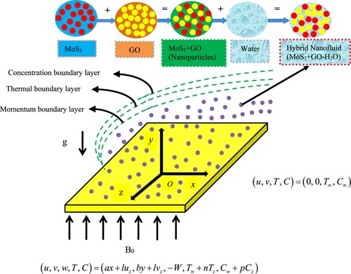
Table 1. Thermophysical properties of solid particles (MoS2 and GO) and base fluid (H2O) [Citation29].
Table 2. Correlation for calculation of effective properties of hybrid nanofluid [Citation29].
2.2. Governing equations
Assuming the stated conditions, the flow model for hybrid nanofluid is [Citation29]
(1)
(1)
(2)
(2)
(3)
(3)
(4)
(4)
(5)
(5)
The conditions at the surface of the plate and far away from the plate
are
(6)
(6) Here, the symbols
,
,
,
,
,
,
,
,
,
,
,
and
present in the above equations represent kinematic viscosity, gravity, density, coefficient of thermal expansion, electrical conductivity, porosity, thermal diffusivity, specific heat, heat source, diffusion coefficient, coefficient of CR, order of CR and slip factors (velocity, thermal and concentration), respectively.
Furthermore, if the terms of Equation (6), i.e. , then the problem is turned into no-slip condition.
The dimensionless system of existing equations can be attained by introducing the following transformations [Citation29]:
(7)
(7) Using similarity transformation defined above and correlations defined in Table , Equation (1) is gratified identically and Equations (2)--(5) take the resulting dimensionless form:
(8)
(8)
(9)
(9)
(10)
(10)
(11)
(11)
with
(12)
(12) where
is the Grashof number,
is the porosity parameter,
is the Eckert number,
is the magnetic parameter,
is the heat generation coefficient,
is the Prandtl number,
is the Schmidt number,
is the CR parameter,
is the suction or injection parameter as
,
is the stretching factor,
are slip (velocity, thermal, concentration) parameters, i.e.
,
,
and
are constants.
2.3. Quantities of engineering and physical importance
The skin-friction coefficients are well-defined as
(13)
Substituting Equation (13) in Equation (12) and using Equation (7), we obtained the following dimension-free form of skin-friction coefficients
The
Again using Equation (7), the expression for and
given in Equation (16) is reduced to the following form:
(17)
(17) where
are termed as local Reynolds number.
3. Methods of solution
3.1. Method 1
Equations (2)–(5) governing the fluid flow subject to Equation (6) are tackled by the numerical method, i.e. Runge-Kutta-Fehlberg (RKF) with shooting scheme. To implement the methodology, the following procedure is followed:
Reduce Equations (2)–(5) to the dimensionless form Equations (8)–(11) and use Equation (7) with associated initial and boundary conditions.
Equations (8)–(11) are highly nonlinear and are discretized to obtain a system of first-order differential equations (DEs).
The obtained system in step 2 is in the form of an initial value problem (IVP) with some missing initial conditions.
Now, putting values to missing initial conditions using the shooting method and solving by the RKF method.
Calculating the residue for far-field conditions and repeat step (4), if residue > error tolerance.
If residue < error tolerance, then the solution is obtained
3.2. Method 2
The solution of Equations (8)–(11) along with Equation (12) is tackled by the bvp4c tool which is available in MATLAB 2020a. For the outcomes of each parameter, the different loop is applied using the bvp4c tool (see [Citation48]). In this article, this tool is particularly used for contour plots.
4. Code of validation
To validate the exactness of our code, values of and
are calculated for the distinct value of
and
and are compared with those of Hayat et al. [Citation10] (see Table ). An excellent agreement between them leads to approval of the accurateness of our codes.
Table 3. Comparison of numerical values of surface drag forces for and
when
and
.
5. Results and discussion
This portion of the research declared the influences of various active parameters, i.e. magnetic field , Grashof number
, porosity
, slip variables (
,
,
), suction
or injection
, Schmidt number
, order of CR
and CR parameter
on physical variables, i.e. velocities
, temperature
and concentration
fields are illustrated through graphs. Furthermore, the behaviour of varying
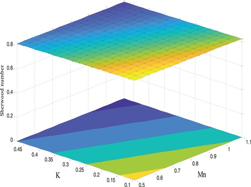
on physical variables, i.e. skin friction, Nusselt number and Sherwood number is illustrated using 2D plots and contour plots and discussed in detail. Moreover, all the computations are conducted by considering the value of
and the concentration of nanoparticles MoS2 and GO as 3% each. To have a better understanding the response of active parameters is categorized in the following section:
Figure 2. Concentration outlines for .
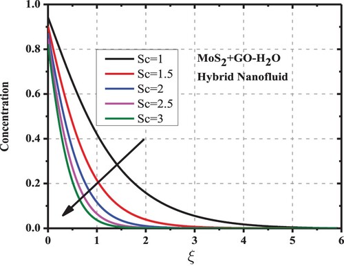
Figure 3. Concentration outlines for .
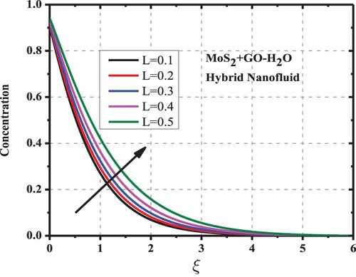
Figure 4. Concentration outlines for .
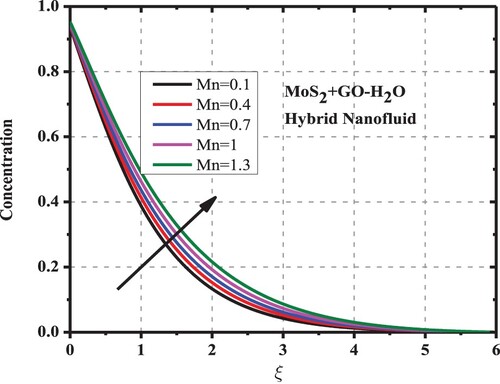
Figure 5. Concentration outlines for .
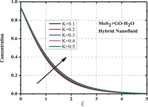
Figure 6. Concentration outlines for .
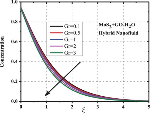
Figure 7. Concentration outlines for .
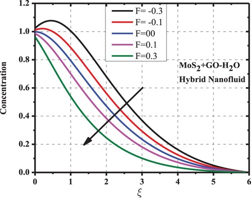
Figure 8. Concentration outlines for .
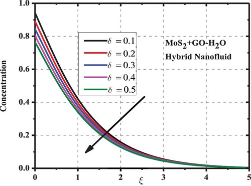
Figure 9. Concentration outlines due to .
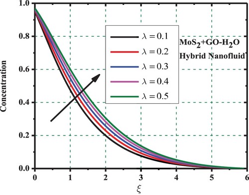
Figure 10. Concentration outlines for .
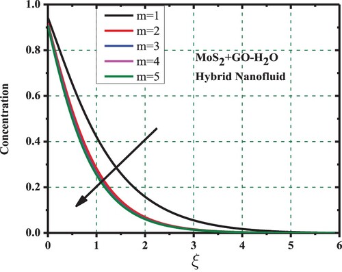
Figure 11. Temperature outlines for .
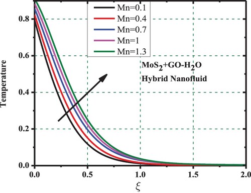
Figure 12. Temperature outlines for .
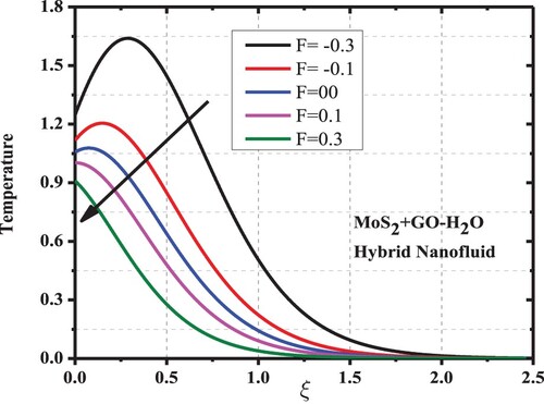
Figure 13. Temperature outlines for .
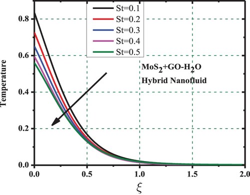
Figure 14. Temperature outlines due to .
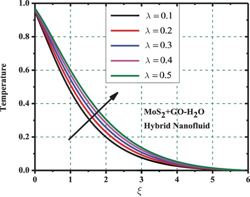
Figure 15. Velocity outlines along x-axis for .
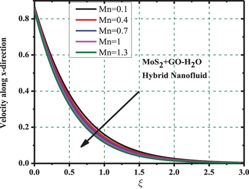
Figure 16. Velocity outlines along x-axis due to .
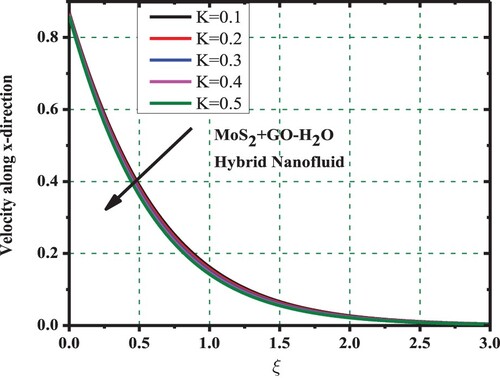
Figure 17. Velocity outlines along x-axis for .
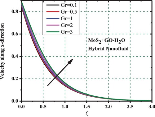
Figure 18. Velocity outlines along x-axis due to .
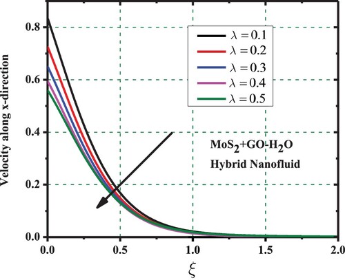
Figure 19. Velocity outlines along x-axis for .
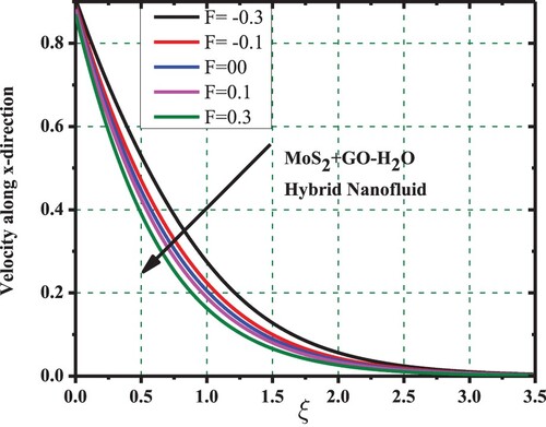
Figure 20. Velocity outlines along y-axis for .
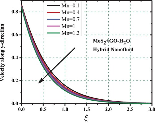
Figure 21. Velocity outlines along y-axis for .
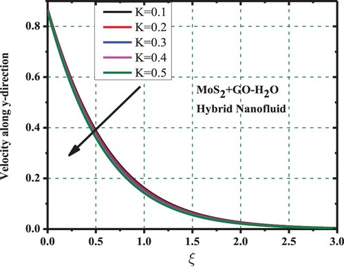
Figure 22. Velocity outlines along y-axis for .
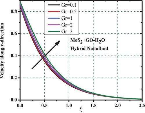
Figure 23. Velocity outlines along y-axis due to .
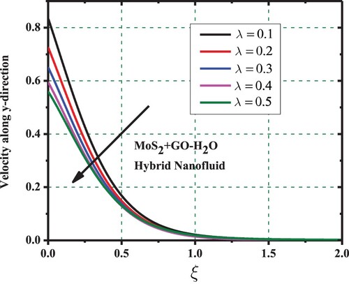
Figure 24. Velocity outlines along y-axis for .
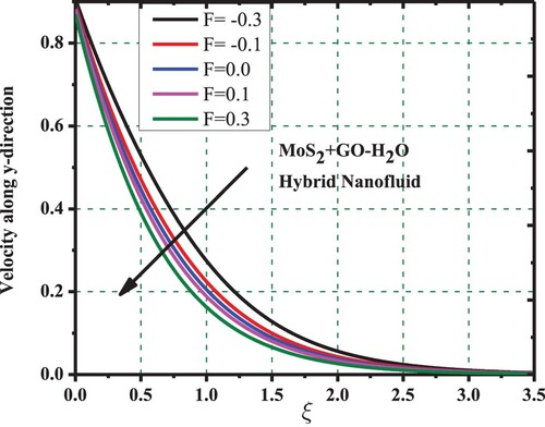
Figure 25. outlines due to
and
.
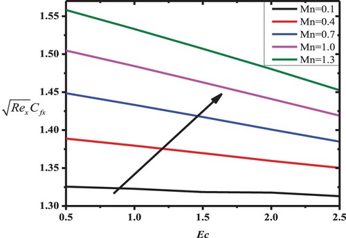
Figure 26. outlines due to
and
.
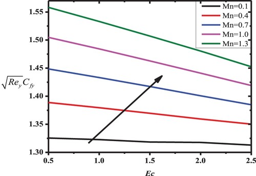
Figure 27. outlines due to
and
.
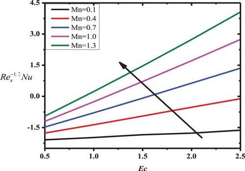
Figure 28. outlines due to
and
.
Concentration profile: The impact of
Temperature profile: Dissimilarity of temperature curves and the associated BL for active parameters
Velocity profile: Figures inspect the aftermath of
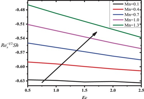
The surface drag forces, Nusselt number and Sherwood number analysis: Impact of variation in the magnitude of magnetic field against Eckert number is outlined for
Figure 29. versus
.

Figure 30. versus
.
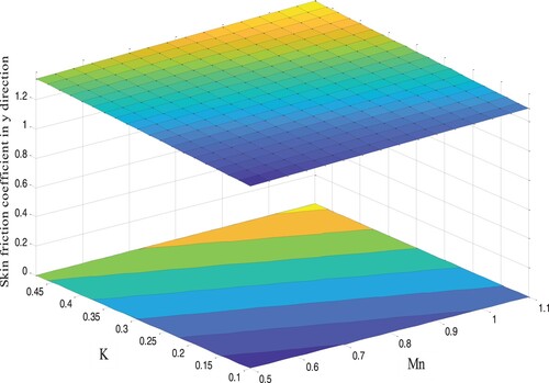
Figure 31. versus
.
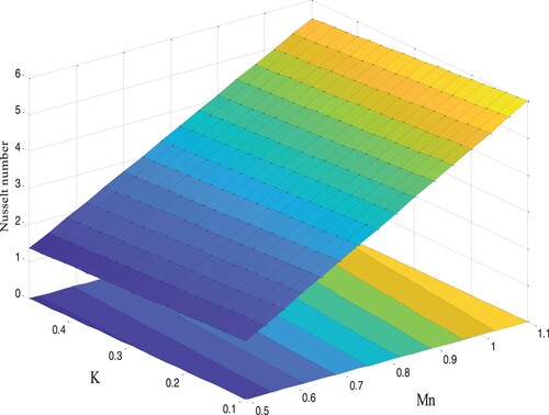
Figure 32. versus
.
6. Closing remarks
The magnetized flow of MoS2–GO/H2O fluid through a porous surface under the condition of multiple slip mechanisms (velocity, thermal and solutal), mth-order CR, suction/blowing and natural convection is presented in this article. The flow model equations are solved by the techniques, i.e. bvp4c and shooting. For the validation of our code, the comparison is made with Hayat et al. [Citation10] for the values and
. The main summary of this research includes the following points:
The heat and mass transfer performance of MoS2-GO/H2O fluid is enhanced with an increase in a magnetic field
The velocities, thermal and concentration distribution outlines of MoS2–GO/H2O are depreciated when the working fluid moves from injection to suction region.
When an increment in the values of
The MoS2–GO/H2O fluid concentration outlinesdepreciated due to a rise in the values of
Mass transfer functions increase with parameters such as magnetic field
On increasing the strength of magnetic field, thermal field is enhanced while both x- and y-directions velocity is reduced.
The velocity functions are reduced with a parameter
The velocity functions of MoS2–GO/H2O are augmented with an increase in Grashof
With the increase in thermal slip
On increasing velocity slip
Disclosure statement
No potential conflict of interest was reported by the authors.
References
- Siddheshwar PG, Mahabaleswar US. Effects of radiation and heat source on MHD flow of a viscoelastic liquid and heat transfer over a stretching sheet. Int J Non-Lin Mech. 2005;40(6):807–820.
- Vajravelu K, Cannon JR. Fluid flow over a nonlinearly stretching sheet. Appl Math Comp. 2006;181(1):609–618.
- Cortell R. Fluid flow and radiative nonlinear heat transfer over a stretching sheet. J King Saud Uni Sci. 2014;26(2):161–167.
- Rashidi MM, Rostami B, Freidoonimehr N, et al. Free convective heat and mass transfer for MHD fluid flow over a permeable vertical stretching sheet in the presence of the radiation and buoyancy effects. Ain Shams Eng J. 2014;5(3):901–912.
- Muhammad T, Hayat T, Shehzad SA, et al. Viscous dissipation and Joule heating effects in MHD 3D flow with heat and mass fluxes. Res Phy. 2018;8:365–371.
- Khan WA, Pop I. Boundary-layer flow of a nanofluid past a stretching sheet. Int J Heat Mass Transf. 2010;53(11–12):2477–2483.
- Hayat T, Imtiaz M, Alsaedi A, et al. MHD three-dimensional flow of nanofluid with velocity slip and nonlinear thermal radiation. J Magn Magn Mater. 2015;396:31–37.
- Sheikholeslami M, Hayat T, Alsaedi A. MHD free convection of Al2O3–water nanofluid considering thermal radiation: a numerical study. Int J Heat Mass Transf. 2016;96:513–524.
- Hayat T, Aziz A, Muhammad T, et al. Three-dimensional flow of nanofluid with heat and mass flux boundary conditions. Chin J Phy. 2017;55(4):1495–1510.
- Hayat T, Khan M, Muhammad T, et al. On model for three-dimensional flow of nanofluid with heat and mass flux boundary conditions. J Therm Sci Eng Appl. 2018;10(3):031003.
- Mahanthesh B, Gireesha BJ, Gorla RS, et al. Magnetohydrodynamic three-dimensional flow of nanofluids with slip and thermal radiation over a nonlinear stretching sheet: a numerical study. Neural Comp Appl. 2018;30(5):1557–1567.
- Reddy PS, Chamkha A. Heat and mass transfer characteristics of MHD three-dimensional flow over a stretching sheet filled with water-based alumina nanofluid. Int J Numl Meth Heat Fluid Flow. 2018;28(3):532–546.
- Mousa MM, Ali MR, Ma WX. A combined method for simulating MHD convection in square cavities through localized heating by method of line and penalty-artificial compressibility. J Taibah Uni Sci. 2021;15(1):208–217.
- Bhatti MM, Zeeshan A, Bashir F, et al. Sinusoidal motion of small particles through a Darcy-Brinkman-Forchheimer microchannel filled with non-Newtonian fluid under electro-osmotic forces. J Taibah Uni Sci. 2021;15(1):514–529.
- Iqbal Z, Maraj EN, Azhar E, et al. A novel development of hybrid (MoS2− SiO2/H2O) nanofluidic curvilinear transport and consequences for effectiveness of shape factors. J Taiwan Inst Cheml Eng. 2017;81:150–158.
- Shaiq S, Maraj EN, Iqbal Z. Remarkable role of C3H8O2 on transportation of MoS2−SiO2 hybrid nanoparticles influenced by thermal deposition and internal heat generation. J Phy Chem Solids. 2019;126:294–303.
- Gugulothu S, Pasam VK. Experimental investigation to study the performance of CNT/MoS2 hybrid nanofluid in turning of AISI 1040 steel. Austr J Mech Eng. 2020: 1–1. doi:10.1080/14484846.2020.1756067.
- Khashi'ie NS, Arifin NM, Pop I, et al. Three-dimensional hybrid nanofluid flow and heat transfer past a permeable stretching/shrinking sheet with velocity slip and convective condition. Chin J Phy. 2020;66:157–171.
- Muhammad K, Hayat T, Alsaedi A, et al. Mixed convective slip flow of hybrid nanofluid (MWCNTs + Cu + water), nanofluid (MWCNTs + water) and base fluid (water): a comparative investigation. J Therm Anal Calorim. 2021;143(2):1523–1536.
- Geim AK, Novoselov KS. The rise of graphene. Nanosci Technol: A Coll Rev Nature J. 2010: 11–19. doi:10.1142/9789814287005_0002.
- Jauregui LA, Yue Y, Sidorov AN, et al. Thermal transport in graphene nanostructures: experiments and simulations. ECS Trans. 2010;28(5):73.
- Balandin AA. Thermal properties of graphene and nanostructured carbon materials. Nat Mater. 2011;10(8):569–581.
- Lee W, Lee JU, Jung BM, et al. Simultaneous enhancement of mechanical, electrical and thermal properties of graphene oxide paper by embedding dopamine. Carbon N Y. 2013;65:296–304.
- Shiu SC, Tsai JL. Characterizing thermal and mechanical properties of graphene/epoxy nanocomposites. Compos Part B: Eng. 2014;56:691–697.
- Aradhana R, Mohanty S, Nayak SK. Comparison of mechanical, electrical and thermal properties ingraphene oxide and reduced graphene oxide filled epoxynanocomposite adhesives. Polymer. 2018;141:109–123.
- Esfahani MR, Languri EM, Nunna MR. Effect of particle size and viscosity on thermal conductivity enhancement of graphene oxide nanofluid. Int Commun Heat Mass Transf. 2016;76:308–315.
- Taherialekouhi R, Rasouli S, Khosravi A. An experimental study on stability and thermal conductivity of water-graphene oxide/aluminum oxide nanoparticles as a cooling hybrid nanofluid. Int J Heat Mass Transf. 2019;145:118751.
- Bhatti MM, Bég OA, Abdelsalam SI. Computational framework of magnetized MgO–Ni/water-based stagnation nanoflow past an elastic stretching surface: application in solar energy coatings. Nanomaterials. 2022;12(7):1049.
- Ghadikolaei SS, Gholinia M. 3D mixed convection MHD flow of GO–MoS2 hybrid nanoparticles in H2O–(CH2OH)2 hybrid base fluid under the effect of H2 bond. Int Commun Heat Mass Transf. 2020;110:104371.
- Afify AA. MHD free convective flow and mass transfer over a stretching sheet with chemical reaction. Heat Mass Transf. 2004;40(6):495–500.
- Rahman MM, Al-Lawatia M. Effects of higher order chemical reaction on micropolar fluid flow on a power law permeable stretched sheet with variable concentration in a porous medium. Can J Chem Eng. 2010;88(1):23–32.
- Arthur EM, Seini IY, Bortteir LB. Analysis of Casson fluid flow over a vertical porous surface with chemical reaction in the presence of magnetic field. J Appl Phys. 2015;3:713–723.
- Seth GS, Sarkar S. Hydromagnetic natural convection flow with induced magnetic field and nth order chemical reaction of a heat absorbing fluid past an impulsively moving vertical plate with ramped temperature. Bulg Chem Commun. 2015;47(1):66–79.
- Seth GS, Bhattacharyya A, Kumar R, et al. Modeling and numerical simulation of hydromagnetic natural convection Casson fluid flow with nth-order chemical reaction and Newtonian heating in porous medium. J Porous Media. 2019;22(9):1141–1157.
- Singh K, Pandey AK, Kumar M. Slip flow of micropolar fluid through a permeable wedge due to the effects of chemical reaction and heat source/sink with Hall and ion-slip currents: an analytic approach. Prop Pow Res. 2020;9(3):289–303.
- Singh K, Kumar M, Pandey AK. Melting and chemical reaction effects in stagnation point flow of micropolar fluid over a stretchable porous medium in the presence of nonuniform heat source/sink. J Porous Media. 2020;23(8):767–781.
- Singh K, Pandey AK, Kumar M. Numerical solution of micropolar fluid flow via stretchable surface with chemical reaction and melting heat transfer using Keller–Box method. Prop Pow Res. 2021;10(2):194–207.
- Gopal D, Saleem S, Jagadha S, et al. Numerical analysis of higher order chemical reaction on electrically MHD nanofluid under influence of viscous dissipation. Alexandria Eng J. 2021;60(1):1861–1871.
- Joshi N, Pandey AK, Upreti H, et al. Mixed convection flow of magnetic hybrid nanofluid over a bidirectional porous surface with internal heat generation and a higher-order chemical reaction. Heat Trans. 2021;50(4):3661–3682.
- Abdelsalam SI, Mekheimer KS, Zaher AZ. Dynamism of a hybrid Casson nanofluid with laser radiation and chemical reaction through sinusoidal channels. Waves Ran Comp Media. 2022. doi:10.1080/17455030.2022.2058714
- Jha BK, Joseph SB, Ajibade AO. Role of diffusion thermo on unsteady natural convection of a chemically reactive fluid impacted by heat source/sink in a tube. J Taibah Uni Sci. 2022;16(1):495–504.
- Algehyne EA, Aldhabani MS, Saeed A, et al. Mixed convective flow of Casson and Oldroyd-B fluids through a stratified stretching sheet with nonlinear thermal radiation and chemical reaction. J Taibah Uni Sci. 2022;16(1):193–203.
- Krishna MV, Ahammad NA, Algehyne EA. Unsteady MHD third-grade fluid past an absorbent high-temperature shrinking sheet packed with silver nanoparticles and non-linear radiation. J Taibah Uni Sci. 2022;16(1):585–593.
- Mahanthesh B, Gireesha BJ, Gorla RS. Nonlinear radiative heat transfer in MHD three-dimensional flow of water based nanofluid over a non-linearly stretching sheet with convective boundary condition. J Niger Math Soc. 2016;35(1):178–198.
- Mahanthesh B, Gireesha BJ, Thammanna GT, et al. Nonlinear convection in nano Maxwell fluid with nonlinear thermal radiation: a three-dimensional study. Alexandria Eng J. 2018;57(3):1927–1935.
- Gireesha BJ, Gorla RSR, Mahanthesh B. Effect of suspended nanoparticles on three-dimensional MHD flow, heat and mass transfer of radiating Eyring–Powell fluid over a stretching sheet. J Nanofluids. 2015;4(4):474–484.
- Thumma T, Mishra SR, Abbas MA, et al. Three-dimensional nanofluid stirring with non-uniform heat source/sink through an elongated sheet. Appl Math Comput. 2022;421:126927.
- Khan M, Ahmad L, Khan WA. Numerically framing the impact of radiation on magnetonanoparticles for 3D Sisko fluid flow. J Braz Soc Mech Sci Eng. 2017;39(11):4475–4487.