
ABSTRACT
Pre-stressing concrete is commonly used in construction. One of the challenges that pre-stressing concrete (PC) faces is that fire exposure reduces the strength and serviceability of PC elements, which requires unique design considerations. The pre-stressing strands are more sensitive to high-temperature, deform larger than mild steel, and break quicker. This research investigates the thermal and structural response of totally unbonded pre-stressing T-beams subjected to increased temperatures and continuous service loads. Thermal coating was proposed to avoid damage and load carrying capacity reduction under fire loading. Seven medium-sized post-tensioned concrete beams were tested in a fire exposure (600°C for 3 h) in order to examine the effect of the following variables: presence of thermal coating, the use of different pre-stressing ratios, increasing the concrete cover, and studying the fire effect at the end anchor, which represents the weakest point at the unbonded system. The proposed insulating technique improved pre-stressing beam behavior during fire exposure by improving crack distribution and lowering strength loss. The thermally insulated beam with a high pre-stressing ratio attained 99.3% of the control specimen load carrying capacity, compared to 86% for the unprotected beam. The deflection of the thermally isolated beam was 7.8 mm, compared to 22.7 mm for the unprotected specimen after 180 min of fire exposure. The use of low pre-stressing ratio caused the insulated pre-stressing strands to rapidly deform with low increases in temperature, which caused rapid crack formation.
Introduction
Pre-stressing concrete is a type of concrete with pre-stressing force which includes balancing and pre-compression loads for post-tensioning systems. Early loading reduces tension stresses and enhances concrete shear strength. However, at high temperatures, the mechanical properties of strands and concrete degrade due to internal physical parameters [Citation1]. This issue is caused by thermal differences between aggregate and cement paste, causing internal stresses and micro-cracks [Citation2,Citation3]. Harmathy [Citation4] has developed constitutive relationships for creep at high temperatures and transient strains, indicating that fire-damaged PC members may not perform as predicted. Reinforced concrete (RC) constructions often use modified or normal strength concrete (NSC), which has good fire-resistant properties due to the absence of admixtures that cause chemical reactions [Citation5–7]. This study aims to investigate the behavior of pre-stressing beams at elevated temperatures of 600°C. Previous research has primarily focused on evaluating bonded pre-stressing PC beams under fire, with little regard given to the capacity of unbonded strands [Citation8]. Design guidelines govern the fire-resistant structural design of unbonded PT structures, but their effectiveness in ensuring fire safety is insufficient (e.g [Citation9–12]).
Pre-stressed concrete structures with pre-stressed steel reinforcement lose their fire resistance as their temperature rises [Citation13]. Pre-stressed beams’ elastic modulus decreases as their temperature rises because of degradation in mechanical properties. When the temperature of the pre-stressed beam is raised by 16°C, the ultimate load decreases by 36% [Citation14]. In a fire scenario, the performance of unbonded post-tensioned (UPT) beams is usually ignored or unknown [Citation15]. Although unbounded post-tension (UPT) has been studied before, it has received less attention than the flexural capacity of bonded pre-stressing concrete beams in a fire. Research shows that the behavior of both partially and fully pre-stressed beams in fire conditions shifts when the concrete cover is increased to 40 mm [Citation16]. It’s possible that spalling of the concrete cover caused by the fire’s direct contact and the loss of retired water from the concrete’s outer shell led to the reduction in failure load. To ensure sufficient serviceability for the desired service loading, it is important to assess how pre-stressed concrete beams perform under service loading characteristics [Citation17]. Camber/deflection, fatigue, cracking, and durability are all factors to think about. Reinforced concrete and PC elements typically lose their strength and adaptability after being exposed to fire [Citation18–20]. The change in color can help identify strength loss [Citation20–23]. The U.S. Navy shipbuilding industry [Citation24,Citation25] is very concerned about the impact of thermal insulation coatings on fire protection. With the help of passive fire protection systems, fires can be contained and prevented from spreading [Citation26]. To investigate the fire performance under service loads, seven fully unbonded pre-stressing T-beams with different strand types were tested in a study.
Experimental program
Five PC T-beams were tested under fire to assess the fire resistance of unbonded pre-stressed simply supported PC T-beams. Two of the tested beams were specified as a control specimen not exposed to fire. Details of the test specimens are depicted in . Seven full-scale PC T-beam specimens were fabricated. The beams were designed as control specimens for the testing program, with a 5-meter simply supported beam according to ASTM El 19 [Citation27], with a post-tensioned system and two strands with a diameter of 15.24 mm (0.6”) or 12.70 mm (0.5”). The beams were fully pre-stressing without main reinforcement rebars and used 8 mm vertical stirrups each 100 mm spacing at first and at the end meter of the beam and 200 mm for the last length of the beam. The top flange had two meshes of 8 mm rebars at 200 mm spacing. To specify the control load, (G1, G2) beams were designed tested under vertical load without fire effect, take in consider that all tested beams have the same section details as shown at .
Figure 1. Details tested beams (G3: G7).
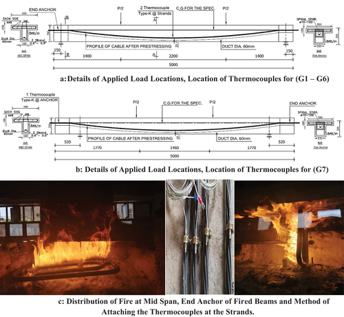
Table 1. Details of tested specimens.
For (G3), the purpose was to investigate the effect of fire flames at the mid-span of the beams at the maximum moment when the insulation coating material was used along the length of the strands. G4 was designed to investigate the effect of fire flames on uncoated strands with a 25-mm concrete cover. G5 was created to investigate the effect of fire flames using the proposed insulation coating system while decreasing the beam’s pre-stressing ratio, whereas G6 was developed using data from earlier studies and suggestions from design codes, and it has a concrete cover of 40 mm (as measured from the stirrups to the concrete’s outside surface) in order to maintain the same effective depth and produce the same control beam’s flexural moment. G7 was tested in order to investigate the effect of a fire flame at the end anchor which regardless of the weakest point in the unbonded pre-stressing system. To ensure that the entire anchoring zone is fully exposed to the fire impact, the position of the oven required repositioning the point loads and the supports for the tested beam to achieve the same design flexural moment for the control beam.
Material properties
Portland cement with a compressive strength of 31.6 MPa was used in ready-mix concrete for beams. The reinforcement materials tested included ASTM A416-included low-relaxation seven-wire strands with 0.6’ (15.24 mm) and 0.5’ (12.70 mm) diameters, a breaking load of 240.8 kN, and a tensile strength of 1720 MPa.
Instruments and setup for the test
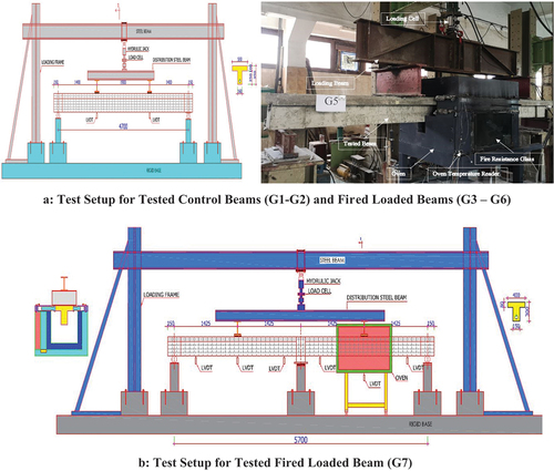
A special furnace chamber measuring 1000 mm in length, 1500 mm in width, and 1000 mm in height was used for fire testing. The specimen was able to bend under the load of the test due to a mechanical system. In order to monitor the beam deformations, three linear variable differential transducers (LVDT) were installed. For 3 h, thermocouples attached to data loggers monitored the furnace’s temperature as it was held at 600 degree Celsius for the test. At the fired beams, the first stage aimed to apply 40% of the ultimate loading of the control beam at the tested beam at ambient temperature, then maintain these loadings for 3 h of firing at 600 C, while monitoring the beam’s behavior, then the specimens were left to cool gradually, while the load was maintained; after that it was continued the loading till the failure to obtain a reduction in the load bearing capacity of these testing beams, as shown in .
Figure 2. Test setup for Both types of tested beams.
The K-type thermocouple was used for measuring data at 600°C after 3 h of exposure. A data collector (UNI-T -UT322) was used to record the temperature of two thermocouples with two channels, with a 0.1ºC error availability per second. An electric thermometer was connected to the furnace to measure the temperature inside the furnace.
Proposed thermal insulation system
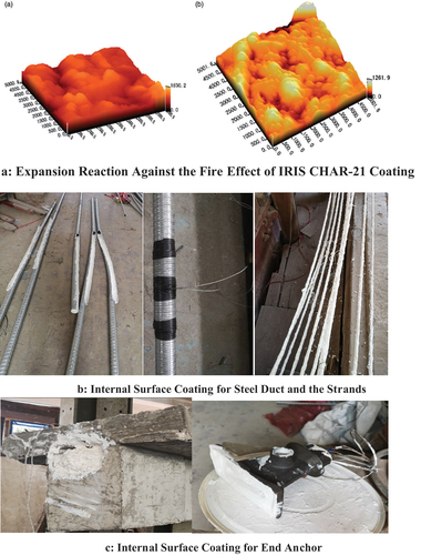
To improve the fire resistance and lower heat transfer, the strands and inner surfaces of specimens (G3, G5 and G6), as shown in were coated with thermal insulation (IRIS CHAR-21) [Citation28,Citation29]. For G7, the end anchor’s internal surface was coated, and after casting, a shield was created to protect the anchor from direct flames as shown in . The coating thickness used was 5 mm at the internal surface of the duct.
Figure 3. Thermal insulation proposed system with the unbonded pre-stressing strands and end anchor.
Results and discussion
Failure modes and crack patterns of the control specimens: (G1, G2)
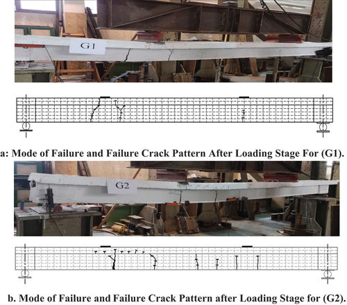
Both G1 and G2 specimen’s brittle failed due to the absence of the non-pre-stressing reinforcing, but the pre-stressing steels ratio affected their crack distribution. G1 began cracking at the mid-span position, with final crack pattern not symmetrical. The width of the left crack increased more than the right side until the failure point. Specimen G2 had better crack distribution along the beam length, with larger numbers and smaller widths due to reduced pre-stressing steel ratio as shown in .
Figure 4. Mode of failure and failure crack pattern of control beams (G1, G2).
Failure modes and crack patterns of the specimens under fire
The tested specimens’ thermal behavior and cracking loads are presented in .
Table 2. Value of service loads, deflections at initial cracking loads and deflection, strand temperature at initial cracking, after 180 min.
Thermal response
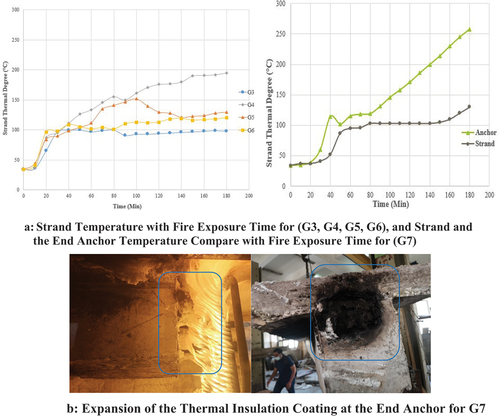
This study explores how fired beam strand thermal temperature increases over time and how each variable affects beam performance. The test uses a gas flame with gas burners and an exhaust system [Citation30,Citation31]. Thermocouples recorded strand temperatures, which increased equally for all the specimens. The strand temperature of Specimen G3, which had thermal insulation, remained constant throughout the fire exposure, while that of Specimen G4, which did not, increased rapidly. The use of thermal insulation resulted in a 50% decrease in strand temperature.
Midspan cracks in specimen G5 caused an increase in strand temperature, which overcame thermal insulation and enhanced deformation. Thermal insulation reduced strand temperature. Specimen G6 behaved similarly until minute 80, when the concrete cover cracked and spalling produced by explosive sounds caused widespread cracks. Thermal insulation stabilized the strands temperature. With insulating the end anchor, the weakest point of the unbonded post-tension system was explored. After a few seconds of fire time, the thermal insulation coating was reacted, creating layers of foaming that darkened before collapsing. Each foaming layer was renewed until 180 min, raising the anchor temperature. During 160 min of fire exposure, the strand temperature did not raise up to 100°C, as shown in . These results are interesting for further research into the effect of thermal insulation on end anchors in unbonded post-tension systems.
Figure 5. Strand temperature with fire exposure time and end anchor thermal behavior with thermal insulation coating.
Load - deflection response
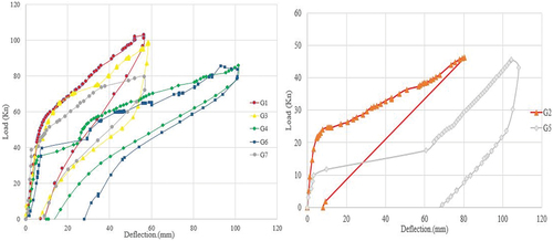
The fire resistance tests showed that all beams (G3 to G7) behaved identically to their reference control beams, with no loading drop or loss at the non-fire stage. The load-deflection curve was similar to control specimen G1, as the final temperature of the strands did not exceed 110°C. Both G1 and G3 had similar failure loads of 103 kN, with G3’s deflection value approximately 59 mm, representing 11.7% increase. After 30 min of fire exposure, water leaking from extended cracks and horizontal and vertical cracks spread, making the beam less stiff. G4 had a failure load of 86 kN (83% of the control beam), losing 17% of its stiffness and a crack deflection of 8.65 mm, a 27% increase from G1.
Specimen G6 had a similar deformation to G4 with a sudden drop at the loading, confirming the negative role of increasing the concrete cover on section stiffness. Beam G7 displayed stable behavior during the fire period, with no loading drops, and a record failure load of 79 kN. Beam G5 recorded the largest deflection value after 43 min of fire exposure. The load-deflection characteristics differ significantly from the control beam with no fire exposure effect, as shown in , by the increasing specimen deflection and the resulting reduced slope of the load-deflection (P-Δ) relation at post-cracking relationships. The rapid occurrence of extended cracks is due to deformation at the small diameter strands brought on by the incrementally slight increase in the temperature degree of the strands.
Figure 6. Load - deflection relationship for all the tested beams.
The failure load (Pu), cracking load (Pcr), and the deflection (Δ) corresponding to each load for each tested beam are summarized in . Initial stiffness (Ki) and Stiffness at 50% of the Failure Point (K-50%) [Citation32] are also given in .
Table 3. Value of loads, deflections at initial and post cracking stages for the tested specimens, initial stiffness (Ki) and stiffness at 50% of the failure point (K-50%).
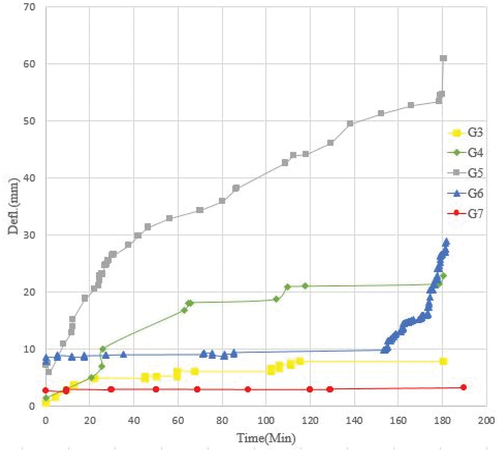
The angle between the load and deflection curves is used to calculate initial stiffness (Ki), whereas stiffness at 50% of the failure point (K-50%) is calculated by dividing the applied load by deflection. Beams with high stiffness values show high resistance behavior. For determining specimen behavior, the relationship between beam deflection and fire exposure time is critical. Thermal insulation coating improves vertical deflection in G3 while increasing concrete cover negatively affects G6. The diameter of pre-stressing strands affects pre-stressing force loss in G5, as shown in .
Figure 7. Beam deflection with fire exposure time for (G3, G4, G5, G6, G7).
show crack patterns and failure modes along the tested beams under fire. G3 did not lose water during fire exposure, as water evaporated from the end. This indicates that the retired internal water did not find any extended cracks and did not cause excessive deformation. Thermal insulation lowered strand temperature, reducing relaxation. At the fire exposure stage, beam G4 created extended cracks due to the absence of thermal insulation. The cracks formed due to strand relaxation allowed some outgoing water to pass through, preventing evaporation at the end anchor. The fire reduced the failure load by 14% and caused diagonal cracks to grow larger than 1 mm after 180 min, allowing water to pass through the cracks. Additionally, many vertical cracks became wider, especially when the load was applied.
Figure 8. Crack pattern and the recorded outgoing water from (G3, G4).
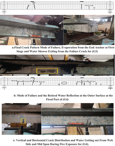
Figure 9. Loading system, final crack pattern and mode of failure of (G5, G6).
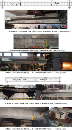
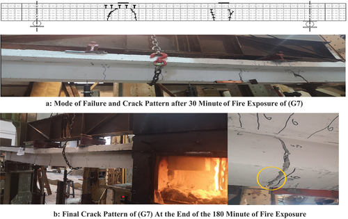
Figure 10. Loading system, final crack pattern and mode of failure of (G7).
After 33 min of fire exposure, beam G5 experienced cracks with water vapor from the end anchor, increasing in width to allow water to pass through. The temperature of the strands increased, resulting in a 1.9% reduction in failure load values and a 33% increase in failure deflection. Beam G6’s deformation behavior was similar to G4, with water evaporating from the end anchors and spalling the concrete cover. The stiffness of G4 decreased due to the reduced resistance of the concrete core to flexure loads and increased spalling during testing, as shown in .
For beam G7, since the fired area of the tested beam was small (End Anchor zone), the amount of evaporation induced by the retired water was low, there was no notable exiting evaporation getting through the end anchor of the specimen during the fire exposure. It was also discovered that some of the existing water got through the extended cracks. As shown in , the final crack distribution was the same as the control beam G1 crack distribution. This demonstrates the good potential of the proposed insulating solution for the end anchor.
Due to the significance of studying the plastic phase of the specimen in addition to the elastic phase, the energy dissipation and stiffness degradation of all specimens were calculated and sketched.
Stiffness degradation and energy dissipation (ed)
The ratio of each load station’s final stiffness to its initial stiffness is stiffness degradation. Stiffness degradation is studied to predict firing beam behavior by linking load station stiffness to initial stiffness [Citation33]. The uncrack loading, fire stage, and final stage are shown in . From loading to 40% of their ultimate load, beams G1 and G2 degraded slightly. G2’s stiffness dropped sharply after 30% and remained low until 60%. Before the fire effect, beams G3, G4, G6, and G7 behaved like G1. G3 and G7 degraded similarly and got close to G1 until the after-fire stage, while G4 and G6 lost about 55% of their stiffness at the fire exposure stage. After fire exposure, G5 lost over 51% of its stiffness. During fire exposure, an unexpected crack caused this loss.
Figure 11. Stiffness degradation over the test lifetime and specimens energy dissipation (ed).
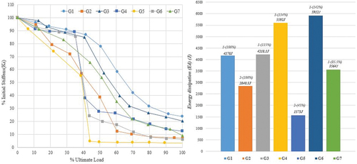
Energy dissipation (Ed) The energy dissipation (Ed) was calculated as the area under the load-deflection curve [Citation34]. Specimens G1, G3, and G7 had the highest ultimate load capacity and lowest deflection values due to the proposed insulating system’s efficiency in increasing beam load capacity and decreasing deflection values in response to fire exposure. G3’s energy until failure increased by 15%, while G7’s decreased by 15%. G4 and G6 had higher deflection but lower failure loads. The high relaxation value of the strands created a large area with deformation and energy, increasing G4 by 34% and G6 by 42%.
G5’s failure energy was 1573J, 45% lower than G2 s. This suggests that the pre-stressing ratio affects fire resistance and that the beam loses most of its load capacity during a fire.
Conclusions
Seven full-scale unbonded pre-stressing beams were tested under different insulation conditions, settings, and pre-stressing ratios to investigate fire behavior of UPT beams:
The fire resistance of the embedded strands was reduced because the thermal conductivity of the concrete changed the strands thermal properties. As a result, it is important to think about how to prevent these losses throughout the design process and apply this protection during construction.
After 30 min of fire exposure, uncoated strands reached 130°C and lost pre-stressing force, causing horizontal and vertical cracks that widened over time. The retained water evaporated leaving internal cracks and voids filled with heated air, increasing internal pressure at cracks.
The recommended solution in design regulations to increase the concrete cover has a negative effect on stiffness degradation because the increased pressure from the retired air rapidly spalls the outer shell, which represents protection from the fire.
The proposed protective system improved UPT system behavior by maintaining strands’ maximum temperature at 103°C during test, preventing cracks and evaporation, promoting internal cooling.
After 180 min, the unprotected specimen with the same pre-stressing ratio deflected by 22.7 mm, while the protected specimen deflected by 7.78 mm.
For beams (G1, G2), changing pre-stressing ratio at ambient temperature increased load capacity by 54% and stiffness degradation by 70%. For beams (G3, G5), increasing pre-stressing ratio at high temperature increased load capacity by 54% and stiffness deterioration by 83%.
For beams (G1, G3), the load capacity decreased by 1% due to pre-stressing ratio at the elevated temperature, with a corresponding increase in stiffness degradation of 14%; for beams (G2, G5), the load capacity decreased by 2% due to pre-stressing ratio at the elevated temperature, with a corresponding decreased in stiffness degradation of 52%.
Beams (G3, G4), at increased temperatures with thermal insulation coating demonstrated a 13% increase in load capacity when using a high pre-stressing ratio, with a 39% increase in stiffness degradation.
For beams (G1, G6), increasing the concrete cover to 40 mm decreased load capacity by 16% and increased stiffness degradation by 42% at elevated temperatures.
Beams (G1, G7) had the same ultimate cracking distribution, confirming that the suggested insulating system protects the end anchor zone from direct flames, with energy dissipation loss of 15% for G7.
Disclosure statement
No potential conflict of interest was reported by the authors.
References
- Khoury GAJPISE, Materials. Effect of fire on concrete and concrete structures. Prog Struct Eng Mater. 2000;2(4):429–447. doi: 10.1002/pse.51
- Purkiss JA, Li L-Y. Fire safety engineering design of structures. CRC press; 2013. doi:10.1201/b16059.
- Ulrich SJFSJ. Concrete at high temperatures—A general review. Fire Saf J. 1988;13(1):55–68. doi: 10.1016/0379-7112(88)90033-1
- Smith, E., & Harmathy, T. (Eds.). Design of Buildings for Fire Safety. ASTM International. 1979. doi:10.1520/stp685-eb
- Asamoto S, Kato K, Maki T. Effect of creep induction at an early age on subsequent prestress loss and structural response of pre-stressing concrete beam. Constr Build Mater. 2014;70:158–164. doi: 10.1016/j.conbuildmat.2014.07.028
- Hou X, Zheng W, Kodur V, et al. Effect of temperature on mechanical properties of pre-stressing bars. Constr Build Mater. 2014;61:24–32. doi: 10.1016/j.conbuildmat.2014.03.001
- Elkady HM, Yasien AM, Elfeky MS, et al. Assessment of mechanical strength of nano silica concrete (NSC) subjected to elevated temperatures. J Struct Fire Eng. 2019;10(1):90–109. doi: 10.1108/JSFE-10-2017-0041
- Gales J, Bisby L, Gillie, M, et al. Unbonded Post Tensioned Concrete Slabs in Fire - Part I - Experimental Response of Unbonded Tendons under Transient Localized Heating. J Struct Fire Eng. 2011;2(3):139–154. doi: 10.1260/2040-2317.2.3.139
- Lucas R. G. Assessment of Impacts from Updating North Dakota?s Residential Energy Code to Comply with the 2000 International Energy Conservation Code. Office of Scientific and Technical Information (OSTI). Dearborn Trade Publishing; 2004. doi:10.2172/860082
- Tso W. K. Overview of seismic provision changes in national building code of Canada, 1990. Earthquake Eng, 743–750; 1990. doi:10.3138/9781487583217-094.
- Code P. Eurocode 2: design of concrete structures-part 1-2: general rules-structural fire design. 2005.
- NZS, The design of concrete structures New Zealand Standard - Concrtete structures Standard . Standards New Zealand Wellington: New Zealand Standards Executive:2006.
- Aimin Y, Yuli D, Litang GJFSJ. Behavior of unbonded pre-stressing continuous concrete slabs with the middle and edge span subjected to fire in sequence. Fire Saf J. 2013;56:20–29. doi: 10.1016/j.firesaf.2012.10.023
- Badawy AH, Hassan, A, El-Kady, H, et al. The behavior of reinforced and pre-stressed concrete beams under elevated temperature. Int J Eng Res Afr. 2020;47:15–30. https://doi.org/10.4028/www.scientific.net/jera.47.15
- Gales J, Bisby LA, Gillie MJFSJ. Unbonded post tensioned concrete in fire: a review of data from furnace tests and real fires. Fire Saf J. 2011;46(4):151–163. doi: 10.1016/j.firesaf.2011.01.004
- Abdelrahman A, et al. Behavior of pre-stressing concrete beams subjected to fire. Housing and Building National Research Centre Journal. 2011; 7, 38-55.
- Moore WL. Performance of fire-damaged pre-stressing concrete bridges. 2008. https://scholarsmine.mst.edu/masters_theses/6778
- Xiong X, Yao GJES. Studies on the static behaviors of unbonded pre-stressing steel reinforced low-strength concrete rectangular frame beams. Eng Struct. 2018;171:982–991. doi: 10.1016/j.engstruct.2018.02.007
- Cattaneo S, Giussani F, Mola F, et al. Flexural behaviour of reinforced, pre-stressing and composite self-consolidating concrete beams. Constr Build Mater. 2012;36:826–837. doi: 10.1016/j.conbuildmat.2012.06.001
- Hussien O, Elafandy THK, Abdelrahman AA, et al. Behavior of bonded and unbonded pre-stressing normal and high strength concrete beams. HBRC J. 2012;8(3):239–251. doi: 10.1016/j.hbrcj.2012.10.008
- Vázquez-Herrero C, Martínez-Lage I, Vázquez-Vázquez H, et al. Comparative study of the flexural behavior of lightweight and normal weight pre-stressing concrete beams. Eng Struct. 2013;56:1868–1879. doi: 10.1016/j.engstruct.2013.08.008
- Du J, Au FTK, Chan EKH, et al. Deflection of unbonded partially pre-stressing concrete continuous beams. Eng Struct. 2016;118:89–96. doi: 10.1016/j.engstruct.2016.03.040
- Kodur V, Dwaikat MJC, Composites C. A numerical model for predicting the fire resistance of reinforced concrete beams. Cem Concr Compos. 2008;30(5):431–443. doi: 10.1016/j.cemconcomp.2007.08.012
- Eamon CD, Jensen EJES. Reliability analysis of pre-stressing concrete beams exposed to fire. Eng Struct. 2012;43:69–77. doi: 10.1016/j.engstruct.2012.05.016
- Gales J, Bisby LA, MacDougall C, et al. Transient high-temperature stress relaxation of pre-stressing tendons in unbonded construction. Fire Saf J. 2009;44(4):570–579. doi: 10.1016/j.firesaf.2008.11.006
- Badawy AH, El-Feky MS, Hassan A, et al. Flexural behavior of unbounded pre-stressed beams modified with carbon nanotubes under elevated temperature. Civil Eng J. 2019;5(4):856–870. doi: 10.28991/cej-2019-03091294
- Gales J, Hartin K, Bisby L. Contemporary Post-tensioned Concrete Construction. Structural Fire Performance of Contemporary Post-tensioned Concrete Construction. Springer; 2016. 7-15.
- Sorathia U, Gracik T, Ness J, et al. Evaluation of intumescent coatings for shipboard fire protection. J Fire Sci. 2003;21(6):423–450. doi: 10.1177/0734904103035393
- Vollaro P, Milella, E, Martone, M, Camino, G, FinA. Intumescent coatings for protection of composites for aircraft application. Carbon. 2014;1:2.
- Cui G, Wang XJSP. Engineering application and study on polyurethane-corrugated steel plate insulation lining of existing railway tunnel in seasonal frozen area. Sci Prog. 2021;104(1):0036850420987043. doi: 10.1177/0036850420987043
- Wu X, Au F, Li J. Posttensioned Concrete Bridge Beams Exposed to Hydrocarbon Fire. J Struct Eng. 2018;146(10). https://doi.org/10.1061/(asce)st.1943-541x.0002791.
- ASTM ABOAS. Standard test methods for fire tests of building construction and materials. 2007. doi:10.1520/e0119-10.
- Abdel-Hady A, Salem S, Khalil A, et al. Experimental assessment for non-monolithic slab-column connections. Ain Shams Eng J. 2021;12(3):2549–2561. doi: 10.1016/j.asej.2021.02.013
- Salem S, Ezzeldin M, El-Dakhakhni W, et al. Out-of-plane behavior of load-bearing reinforced masonry shear walls. J Struct Eng. 2019;145(11):04019127. doi: 10.1061/(ASCE)ST.1943-541X.0002403