
 ?Mathematical formulae have been encoded as MathML and are displayed in this HTML version using MathJax in order to improve their display. Uncheck the box to turn MathJax off. This feature requires Javascript. Click on a formula to zoom.
ABSTRACT
One of the most common statistical systems used in structures especially for wide span slabs are ribbed slabs with shallow wide beams (SWB). This experimental study aimed to investigate and enhance the flexural behavior of high-strength concrete SWB using hybrid longitudinal reinforcement from steel and advanced composite materials as a tensile main reinforcement in SWB. Longitudinal advanced composite bars locally manufactured from ribbed glass fiber reinforced polymer (GFRP) and the second type was ribbed basalt fiber reinforced polymer (BFRP). A group of six half scale SWB were examined in structures laboratory of American University in Cairo with dimensions 2.1 × 0.6 × 0.25 m for length (L), width (B) and depth (d) respectively with constant size effect (d/B). The first three specimens were completely reinforced at tension side with Steel, GFRP or BFRP ribbed bars to be considered a control specimen. Use of GFRP and BFRP bars enhanced the flexural capacity of SWB with 41% and 43% respectively compared to specimen completely reinforced with steel. But on the other hand, the crack propagation of specimens completely reinforced with GFRP and BFRP developed more quickly and had larger crack width compared to specimen completely reinforced with steel. Hybrid reinforcement from Steel with GFRP, Steel with BFRP and Steel with GFRP and BFRP specimens are used to enhance the crack pattern and mode of failure without a significant loss in flexural capacity of SWB. The flexural capacity of these three specimens was enhanced with 26%, 30% and 41% with a significant enhancement in crack pattern and ductility.
Introduction
Shallow wide hidden beams of flooring systems in most structures including major facilities and advantages. They reduce the clearance of floor height, save the material cost and framework. One of the most common statistical systems used in the middle east are ribbed slabs with hollow blocks using shallow wide beams. Decreasing of depth to width ratio (d/B) of SWB leads to deficiency of flexural capacity for these beams. Indeed, a huge number of concrete structures around the middle east region were built utilizing this floor pattern and are structurally weak by historical code standards. To maintain the structural integrity of these facilities and promote public safety, strengthening and restoration are considered necessary. A total of six full-scale shallow wide beams and tested to failure [Citation1]. The test results showed significant improvement in the flexural performance of the strengthened beams with respect to flexural capacity, flexural stiffness, and crack width. Only a few researches on beams with a cross section depth less than its width have been published. Two CFRP-strengthened beams were used to compare the performance of shallow RC beams strengthened with steel reinforced polymer. To examine the performance of shallow RC beams enhanced using steel reinforced polymer, two CFRP-strengthened beams were investigated [Citation2]. Fiber reinforced polymers have been developed via research and innovation in the field of composite materials to be used for structural strengthening and restoration. Fiber reinforced polymers have been developed through research and innovation in the field of composite materials to be used for structural strengthening. The experimental data provided [Citation3] to determine the efficiency of BFRP for reinforcing reinforced concrete beams. The BFRP fabric proved to be effective for increasing both the shear strength and the flexural capacity of the tested beams. Significant improvement of the ductility of the specimens was obtained as well. The Egyptian code [Citation4] does not consider the contribution for shear reinforcement in ultimate shear strength of beams with a width higher than depth, in contrast to international codes [Citation5–8]. The most extensively used reinforcing materials for strengthening and retrofitting RC structural members, both in flexure and in shear, are fiber reinforced polymers (FRP) [Citation9–14].
As a result, considerable cross-sectional concrete zones must be given to meet one-way shear needs. While the regulation disregards the web reinforcement contribution to shear strength, a minimum web reinforcement is provided in actuality. The code’s restrictions result in a very conservative, uneconomic shear design of shallow wide beams. This study also confirmed the efficiency of shear reinforcement in enhancing the shear strength of shallow wide beams. While, shear failure was delayed through increasing stirrups web shear reinforcement compared to flexural failure at which accelerated [Citation15,Citation16].
The flexural behavior of FRP reinforced beams exhibits no ductility as occurs in the steel reinforced structures [Citation17]. Nine beams strengthened using locally made hybrid fiber reinforced polymer (HFRP) bars were examined. While carbon-glass and aramid-glass hybrid fibers were utilized, HFRP bars with the used bars anchoring significantly improved the behavior of concrete beams reinforced with FRP bars.
When reinforced concrete buildings are subjected to extremely sensitive climates, the steel reinforcement corrodes, thereby reducing the structure’s longevity and serviceability [Citation18,Citation19]. Corrosion in steel reinforcement is caused by carbonation or chlorides. Thus, steel reinforcement can be used in place of corrosion-resistant fiber-reinforced polymer rebars. Because FRP rebars are lightweight, non-magnetic, anti-corrosive, resistant to high temperatures, easy to maintain, and permanent, numerous investigators are looking into their application. Measurements focused on the ductility, load bearing capability, and failure mechanisms of a particular application of FRP bar.
Until now, it seems out that there is a gap in studying the effects of using hybrid longitudinal reinforcement from steel with GFRP or steel with BFRP with different ratios on the flexural behavior espicialy in shallow wide beams. Hybrid reinforcement have a significant effect on flexural capacity, reasonable ductility, the crack pattern, and mode of failure of SWB, especially in case of taking contribution of stirrups into consideration. Therefore, the aim of this research is to study the flexural behavior of high-strength concrete shallow wide beams reinforced by hybrid longitudinal reinforcement.
Research significance
Shallow wide beams are a significant efficient structural system. It is economical and is widely used in different structural applications such as floors, roofs of buildings. Advanced composite materials such as BFRP and GFRP are one of the most important longitudinal tensile reinforcement systems. Contribution of GFRP and BFRP in resisting flexural stresses of shallow wide beams were most significant compared to steel tensile reinforcement. In an attempt to overcome ductility decreasing, a hybrid reinforcement system technique from steel with GFRP or BFRP or with the two types together were proposed. The experimental results showed a great significant for the proposed hybrid longitudinal tensile reinforcement in flexural capacity and ductility enhancement.
Experimental program
Materials
The concrete mix was provided by structures laboratory of American University in Cairo. The concrete was designed to have a 28-days cube compressive strength of about 40MPa. presents the mix proportions to produce one cubic meter of the concrete mix presents the mix proportions to produce one cubic meter of the concrete mix.
Table 1. Concrete mix proportions.
The grading curves for used crushed dolomite and fine sand are presented in . respectively. Aggregates were clean, hard, strong, and durable particles that are largely free of absorbed chemicals, coatings of clay, and other fine materials. Normal weight aggregates meet the requirements of ASTM C33 [Citation20]. Where, the grading limits are usually expressed as the percentage of material passing each sieve. Values of used fine aggregate in . Conforming within the limits of ASTM C33 for fine aggregate at which percent passing by mass were 99, 92.8, 80.5, 50.5, 26.5 and 5.7 for sieve size in (mm) 4.75, 2.36, 1.18, 0.6, 0.3 and 0.15 respectively. Also, the fine aggregate hadn’t more than 45% retained between any two consecutive standard sieves. The grading of coarse aggregate ASTM C33 permit a wide range in grading and a variety in grading size. Grading curve for crushed dolomite in meets the grading requirements for coarse aggregate according to ASTM C33 at which all of the particles pass the 25 mm sieve. According to grading curve of used crushed dolomite in and the definition of the maximum nominal size of aggregate (ASTM C33), the smallest sieve size through which the major portion of the aggregate must pass (typically 85% to 95% passing) equal 15 mm. Ordinary Portland cement from Qena Factory of cement had been used in this study and the chemical composites are shown in .
Figure 1. The grading curve for crushed dolomite.
Figure 2. The grading curve for fine sand.
Table 2. The chemical composites of ordinary Portland cement.
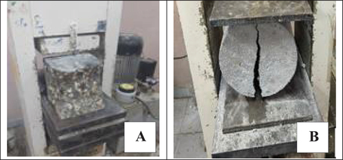
For hardened concrete testing, experimental tests were conducted for concrete, characteristic compressive strength and splitting tensile strength. The average values of three standard cubes, cylinders were tested after 28 days, recorded 40 MPa and 6 MPa for compressive strength and splitting tensile strength respectively. shows the mode of failure of standard cube and cylinder. The standards principle followed for the uniaxial compressive tests states, specimens are loaded to failure in a compression testing machine conforming to EN12390–4 [Citation21]. The maximum load sustained by the specimen is recorded and the compressive strength of the concrete is calculated. The test specimen shall be a cube meeting the requirements of EN 12,350–1 [Citation22]. The load bearing surface of the cubes shall be molded in the case of cube specimen or ground or capped in accordance with NP EN 12,390–3:2011 [Citation23]. During preparing the cubes, the packing didn’t use, other than auxiliary plates between the specimen and the plates of the testing machine conforming to EN 12,390–4. Consequently, a constant rate of loading within range of . Also, the initial application load didn’t exceed approximately 30% of the ultimate failure load. Finally, apply the load to the specimens without shock and increased incrementally by
. . A shows semi-explosive failure for standard tested cubes at which meets satisfactory standard mode of failure. Modulus of elasticity for examined concrete empirically computed according to ECP 203–2018 [Citation4] as
(MPa) at which equal to 27,828 MPa. On the other hand, the splitting tensile strength test method consists of applying a diametric compressive force along the length of a cylindrical concrete specimen with a constant rate of loading according to ASTM C496/C496M [Citation24]. Two bearing strips of nominal 3.0 mm thick, free of imperfections, wide larger than the diameter of the test specimen and of a length slightly longer than that of tested cylinder specimens as shown in . B. According to ASTM C496/C496M, the diameter of cylinder test specimen (D) measured to the nearest 0.25 mm by averaging three diameters at the ends and the middle of the specimens. The length of tested cylinders (L) calculated to the nearest 2 mm by averaging at least two length measurement’s. Finally, tensile splitting strength may be calculated as
, in which p is maximum recorded failure load.
Figure 3. Mode of failure for standard A) compressive strength of cubes, B) tensile strength of cylinders.
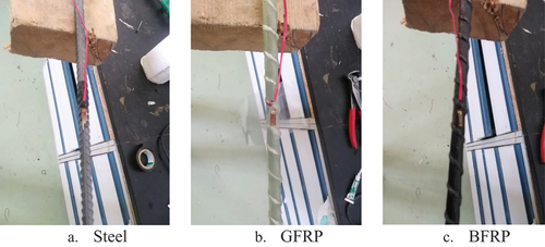
The tensile mechanical properties of the steel bars were tested according to ASTM A370-97a. presents the yield strength, ultimate strength, elongation and modulus of elasticity for steel reinforcement. presents the ultimate tensile strength versus corresponding strains and modulus of elasticity for various types of GFRP and BFRP bars as recorded at the AUC material lab. . shows the tensile test for steel, BFRP and GFRP bars, . shows the relationship between ultimate tensile strength and corresponding strains for examined GFRP and BFRP.
Figure 4. Tensile strength test for A) steel B) BFRP, and C) GFRP.
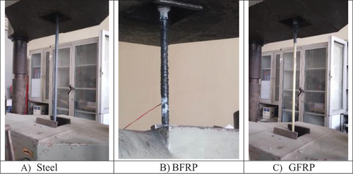
Figure 5. Ultimate tensile strength versus corresponding strains for examined BFRP and GFRP.
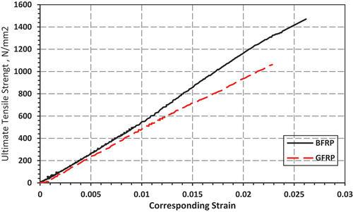
Table 3. The yield strength, ultimate strength and elongation.
Table 4. Ultimate tensile strength versus corresponding strains and modulus of elasticity of GFRP and BFRP.
Tested shallow wide beams
A total of six half-scale SWB specimens were experimentally tested, all tested SWB with overall thickness equal to 250 mm and span equal 2400 mm with clear span between supported rods equal to 2100 mm in which all specimens have 600 mm width. A total of six SWB with constant width to depth ratio equal 2.4 and reinforced by different flexural longitudinal reinforcement were tested under two points flexural loading. The concrete clear cover was 15 mm to the top and bottom face of all tested specimens. All SWB were reinforced with top compression longitudinal steel bars with 5Φ10. Shear stirrups reinforcement were Φ10@125 mm. All SWB were reinforced with five longitudinal bars with diameter Φ12 with identified reinforcement ratio equal 0.004 as a percentage of considered concrete dimensions. summarizes the general description for longitudinal tensile reinforcement of all the tested SWB specimens which this percentage of longitudinal tensile reinforcement calculated as the number of each type of reinforcement divided on the total number of all tensile reinforcement which equal five. . show experimental details for specimens with different flexural reinforcement technique. Test setup of all specimens could be showed in .
Figure 6. Geometrical dimensions and reinforcement details of experimental specimen’s
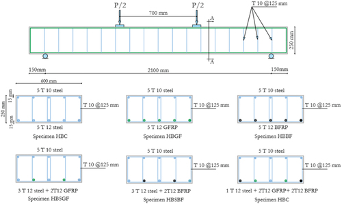
Figure 7. Specimens with different flexural reinforcement technique.
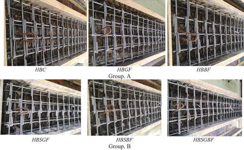
Figure 8. Test setup of all shallow wide beams (SWB) specimens.
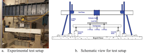
Table 5. General description for longitudinal tensile reinforcement of all the tested SWB specimens.
Electrical strain gauges
For each specimen, strain gauges were used to monitor the flexural longitudinal reinforcement strain at tension side for steel, GFRP or BFRP bars. However, for hybrid specimen, two strains were used to monitor strain of tension resisting bars. . illustrates the installation of strain gauges for different configuration of reinforcement steel, GFRP and BFRP bars.
Figure 9. Installation of strain gauges for steel, GFRP and BFRP bars.
The effectiveness of the strain gauges was confirmed by connecting both ends of the gauge wire to the Avometer device, and a reading of 120 ohms was confirmed. Then all the gauges were connected to several channels in the data logger device, and the correction coefficient was entered for the gauge readings and its value is (2/gauge factor), where the value of the gauge factor is variable and is obtained from the technical information written on its packaging and the recorded readings are in micro strain units.
Deflection of specimens were measured using three linear variable differential transducers located at 1/4, 1/2 and 3/4 the span as shown in . In order to ensure flexural failure pattern, Electrical strain gauges with 10 mm length, 119.8 ± 0.2 ohms’ resistance were used to measure shear strain in web shear reinforcement at d/2 from support line, to ensure adequate shear capacity of tested specimen.
Test results and discussions
This section explains the test results and observed behavior of the tested shallow wide beams. The experimental results included the crack pattern characteristics, records of applied load versus vertical deflection, strain in tensile and shear reinforcement.
Crack pattern characteristics
Test specimen ‘HBC’ which reinforced by steel bars showed ductile behavior. The crack pattern was pure flexural without any significant shear cracks. It could be noted that type of failure was semi ductile for specimens in which completely reinforced by GFRP or BFRP bars for specimens ‘HBGF’ and ‘HBBF’ respectively. Especially, crack width for specimen ‘HBBF’ was more aggressive and suddenly failed compared to control specimen ‘HBC’. On the other hand, for specimens which hybrid reinforced by GFRP with steel ‘HBSGF’ or BFRP with steel ‘HBSBF’ the cracks eliminate and became smaller in width than specimens which completely reinforced by GFRP or BFRP. The cracks absorption of specimens reinforced with hybrid longitudinal reinforcement was very interested, as it was observed that their flexural loading capacity increased in parallel the crack propagations also increased. And it was noted that the ductile behavior recovered again at failure stage. The crack pattern and mode of failures for all shallow wide beams plotted in at which all recorded loads by kN. Also, the schematic diagrams of crack patterns at load levels plotted in , as a providing a visual representation to experimental findings. In this context, specimen ‘HBC’ initiated first flexural crack at load level 65kN and mid span deflection of 1.51 mm, most crack development was flexural cracks but, some flexural shear cracks were found at the load level of 134kN and 144 kN, at failure stage for this specimen, the flexural tension failure cracks was governed and the mode of failure was ductile, this reflects positively on the overall structural performance. For specimen ‘HBGF’ which completely reinforced at tension by GFRP bars, the initial crack recorded at load 65kN with mid span deflection of 2.82 mm, the crack monitored at deflection value higher than its similar of control specimen, this is give indication that the stiffness degraded compared to the control specimen, consequently some shear cracks were observed at 190kNup to 200kN with mid span deflection 28 mm, this gives an indication that the specimen flexural strength capacity was larger than control specimen, finally the cracks propagated again at mid span with recorded load of 310 kN until semi sudden balanced failure was occurred, This gives an indication that specimen which completely tensioned reinforced by GFRP bars had a large flexural strength capacity which is characteristic for large spans of SWB, but with low level of ductility and indications of failure.
Figure 10. The crack pattern and mode of failure for all specimens.
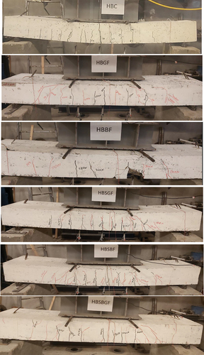
Figure 11. The schematic diagrams for crack pattern and mode of failure for all specimens.
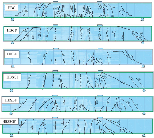
For specimen ‘HBBF’ the flexural crack developed at 76 kN carried out by 5.6 mm mid span deflection. The specimens had a limited crack propagation compared to control specimen until shear cracks occurred at 130 kN and 147 kN, there was a significant flexural shear cracks until a sudden brittle failure occurred at high level of load equal 343kN, this reflects the high ability of flexural strength for highly loaded SWB in structures, on the other hand, with losing failure warning feature which lead to maximize strength reduction factors for concrete and BFRP in design criteria. For specimen ‘HBSGF’ which hybrid reinforced by 3T12 steel bars with 2T12 GFRP bars the flexural crack initiated at load level of 71 kN with mid span deflection 2.39 mm, consequently the cracks eliminate and the overall behavior was ductile compared to control specimen, so, this hybrid reinforcement from steel and GFRP bars enhanced flexural capacity and crack pattern of SWB with maintaining ductile behavior. For specimen ‘HBSBF’ at which completely reinforced with 3T12 steel with 2T12 BFRP bars, the crack initiated early at load level of 69kN with mid span deflection of 2.3 mm, it could be noted that the specimen highly improved in the crack pattern compared to specimen ‘HBBF’, the specimen absorbed a large amount of flexural loads and the failure was ductile. The last specimen ‘HBSBGF’ which reinforced by 1T12 steel, 2T12 GFRP and 2T12 BFRP, the flexural crack initiated at 49 kN with mid span deflection 1.53 mm, there are shear cracks observed at 154kN and 192kN, Although the specimen contains one steel reinforcement bar, it played good role in maintaining the ductility of the specimen. Over all, using of hybrid longitudinal steel reinforcement has a dual positive role in enhancing the flexural crack pattern and maintaining a large amount of strength and ductility for large spans or heavy loaded SWB in structures.
Load-vertical deflection relation
The deflections were measured by LVDTs at equally spaced locations. The deflection profile showed the deformational response to LVDTs locations for different reinforcement configuration as presented in . While the load deflection relation at mid span for different beams is presented in . It can be noticed that the usage of advanced composite bars increased the flexural load capacity for beams.
Figure 12. Deflection profile for all tested specimens.
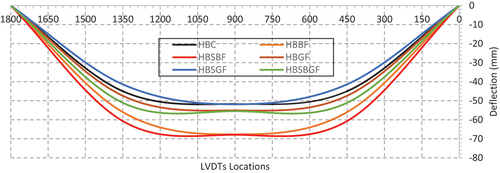
Figure 13. The load deflection curves for all tested specimens.
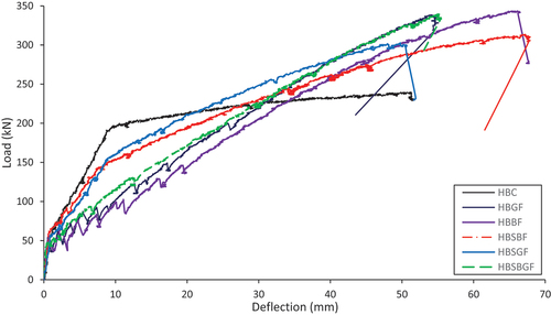
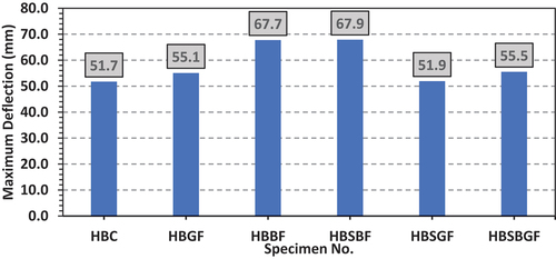
The results presented a good enhancement for load capacity and deformations. The specimens in which reinforced by fully GFRP and BFRP enhanced flexural capacity by 41% and 43% respectively. But the behavior of these specimens was semi ductile in which the cracks was highly propagation was rapid and wider cracks were induced compared to fully reinforced steel specimens. The concept of using hybrid longitudinal reinforcement comes from here, where three alternative hybrid reinforcement models were proposed. The specimen which is reinforced by dual longitudinal reinforcement from steel and BFRP enhanced the flexural capacity by 30% while maintaining ductile behavior. The second hybrid model reinforced by steel and GFRP gave 26% improvement in flexural capacity and had better ductile behavior. The usage of the three types of longitudinal reinforcement from steel, GFRP and BFRP was the third hybrid model. This hybrid model enhanced the flexural capacity by 41% and had the best ductility behavior. show the peak flexural capacity and the corresponding maximum deflection for all specimens.
Figure 14. Recorded peak load for all specimens.
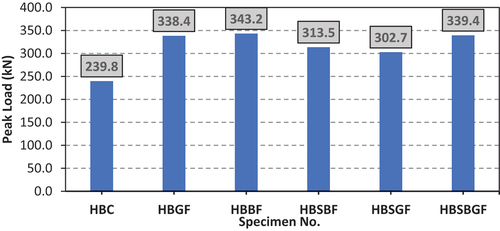
Figure 15. Recorded maximum deflection for all specimens.
Recorded strains in longitudinal RFT
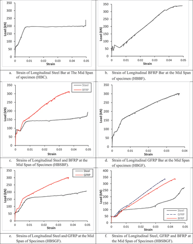
The maximum strain in tensile steel recorded at the mid span of the longitudinal reinforcement of all shallow wide beams. For control specimen HBC, it could be noted that the strain in steel rebar reached the maximum value of 0.05 at peak load of 200 kN. The maximum strain exceeded 0.05 at the peak load of 240 kN for the control specimen HBC while the maximum captured strain of 0.05 was recorded due to the strain gauge physical limitation. The high ductility of the steel reinforcement can be correlated to the load deflection curve of the HBC beam presented in . The strain in BFRP presented in impressively reached 0.05with less ductility compared to steel at failure load of 349kN. The hybrid reinforcement of BFRP and steel presented in had an interesting behavior at which the steel reinforcement had lower strain values compared to BFRP bars till the occurrence of first crack, then the steel bar gain strain till ductile behavior at about 140kN. Upon the yielding of steel bars at 140 kN the BFRP bar started to gain high strain values reaching about 0.037. presented strain of GFRP at which strain of 0.0037 reached corresponding to 300kN, while the same pattern of hybrid system occurred when using GFRP and steel reinforcement as presented in . illustrates the strain distribution corresponding to applied load for different reinforcement types in HBSBGF. It can be noticed the ductility gained from using steel and the strength gained from using FRP bars.
Figure 16. Recorded maximum strain in resisting tensile element for all specimens.
illustrates the load corresponding to first crack appearance in tested beams, initial crack displacement, maximum load, maximum deflection, beam ductility index and beam energy absorption for different tested beams. The peak values can be explained by the behavior shown previously in . Where the ductility index calculated as the ratio between the maximum and the minimum deflection at 80 % from failure load, consequently the energy absorption was computed as the integrated area under the load – deflection curve.
Table 6. Presentation of first cracking load, initial crack displacement, maximum load, maximum deflection, ductility index and energy absorption for tested beams.
Finite-element (FE) modeling of the BEAMS
Simulated shallow wide beams
ANSYS 2019-R2 software was used to investigate the flexural behavior of high strength concrete shallow wide beams reinforced with hybrid longitudinal reinforcement. The numerical model was developed to validate the experimental test results.
Materials of the Fe model
3D FE models were presented using ANSYS software. The simulated materials are discussed as following:
Concrete
Non-metal plasticity model of concrete in ANSYS was used to simulate the behavior of concrete. Uniaxial cracking and crushing strength are two failure mechanisms considered in this model. The stress versus inelastic strain curve of concrete was given in . The tensile behavior of concrete is considered to be linear-elastic until the crack initiation, which corresponds to the uniaxial cracking strength. The crushed stiffness factor was used to define the negative stiffness of concrete. A linear relationship between stress and strain is considered up to 30% of peak strength (fc’) for uniaxial compression behavior of high strength concrete. summarized the FEM material properties for concrete
Figure 17. Concrete compressive stress - inelastic strain.
Table 7. FEM material properties for concrete.
Steel and frp reinforcement
The relationship between stress and strain for the mild-steel bars was considered to be elastic-perfectly plastic. While for FRP bars, the stress-strain curve was considered to be linear up to rupture strain, where the loading capacity was lost, as illustrated in .
Figure 18. Stress-strain relationship for steel and FRP reinforcement [Citation25].
![Figure 18. Stress-strain relationship for steel and FRP reinforcement [Citation25].](/cms/asset/49331f1d-b56f-41cf-918c-cc7eaf6664c5/thbr_a_2309818_f0018_oc.jpg)
showed the needed parameters to assign the models material properties for, steel bars, BFRP and GFRP bars respectively.
Table 8. FEM material properties for reinforcing steel bars.
Table 9. FEM material properties for BFRP bars.
Table 10. FEM material properties for GFRP bars.
3D beam model
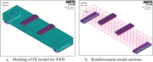
A 3D ANSYS/standard was used to model the FRP reinforced high strength concrete shallow wide beams (SWB). . shows meshing and geometry of the modeled beams, while the longitudinal and web shear reinforcement, support plates and loading plate of the same model are shown in . One support was considered a roller while the other support was considered a hinged. The concrete was selected as a SOLID 65, while the steel plates support and loading plates were used SOLID 185. Both the steel and FRP reinforcement are modeled as a 2 node 3-D finite truss element LINK 180. The bond between concrete and all reinforcement was considered as a fully bond.
Figure 19. Details of FE model for shallow wide beams.
Validation of FE model
The proposed model was conducted based on the experimental program according to crack pattern and mode of failure, ultimate capacity load and maximum deflection, strain in longitudinal reinforcement. The crack pattern and mode of failure for FE model shallow wide beams were compatible with the obtained from experimental tests. Consequently, the numerical results were found a satisfied convergence of high strength concrete shallow wide beams with the experimental ones. Both experimental and numerical results of comparison is shown in . . shows the load-deflection relationship for both experimental and FEA model. . shows crack pattern and mode of failure for numerical for both types of failure. An appropriate meshing size of the beams were chosen, at a value of 50 mm, to monitor all variables at the 8 points of contact for the beam along the entire length. On the other hand, the meshing sizes were intensified to reach approximately 20 mm near loading and supported bearing plates in order to accommodate the predicted concentration of stresses in these locations.
Figure 20. Load-deflection relationship of both experimental and FEA model for control beam HBC.
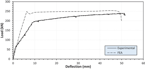
Figure 21. The crack pattern and mode of failure for both types of failure (FEA).
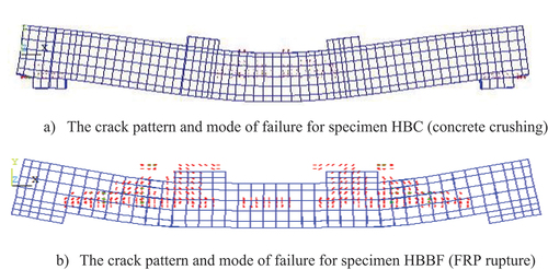
Table 11. Experimental results versus FE model results.
Theoretical expectations
Providing a theoretical explanations and prediction of ultimate flexural loading capacity taking in to consideration crack initiation and yielding points will contribute to a more insightful interpretation of the load-deflection behavior. This theoretical expectations strategy will aid in reaching stronger findings about the effectiveness of different longitudinal reinforcement systems considered in this study.
Cracking initiation stage
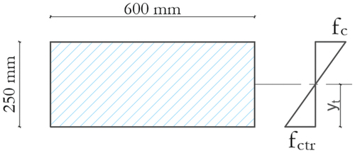
Theoretical expectation of cracking initiation will be carried out through the following governing equation according to ECP 203–2018 [Citation4]. .show stresses characteristics for all specimens at cracking initiation stage.
Figure 22. Stresses characteristics at cracking initiation stage for all specimens.
Where:
yt: distance from neutral axe to the most tensioned fiber of concrete
fctr: cracking strength of concrete in case of applied to pure flexural moment
Igross: gross moment of intertia about axe of rotation
Mcrack: cracking initiation moment
Pcracking: theortical expectation for crack initiation load
Ultimate behavior stage
Distinctive features such as yielding point for steel or proofing strength for GFRP, BFRP and post-peak behavior of concrete will govern this stage. Also, there are two conditions will be into consideration, the first is strain compatibility between concrete and steel or GFRP or BFRP, the second is equilibrium condition. The theoretical expectations for control specimen ‘HBC’ will be presented in details through the following equations and the whole results of other specimens will be presented and compared to experimental results in for cracking load and ultimate load respectively. Where, stresses and strains characteristics at ultimate stage for control beam ‘HBC’ will be plotted in . All theoretical expectations were under estimated compared to experimental results which confirmed conservation theory of design codes.
Figure 23. Stresses characteristics at ultimate stage for control specimen HBC.
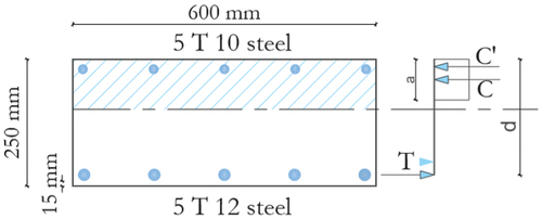
Table 12. Comparison between experimental results versus theoretical expectations.
Table 13. Comparison between experimental results versus theoretical expectations.
Conclusions
This study investigates experimentally the behavior of RC shallow wide beams reinforced by hybrid longitudinal reinforcement techniques. The main parameters of the study were the reinforcing bars type: steel, GFRP, BFRP. Based on the results obtained, the following conclusions could be drawn:
The usage of steel stirrups increased the shear capacity of the beams, as no shear cracks were developed during testing. This point was validated by low strains measuring in steel stirrups during testing. Never the less, conservative code of practice as ECP 203-2018 or ACI 318-14 ignored the contribution of steel stirrups in shear resistance of shallow wide beams.
Shallow wide beams which were fully reinforced by GFRP and BFRP at tension side increased the flexural capacity by 41% and 43% respectively compared to control specimen.
Failure mechanism of shallow wide beams reinforced with FRP only were semi brittle compared to that reinforced with steel, at which ductile failure mechanism were noticed.
Hybrid longitudinal tensile reinforcement of BFRP or GFRP and steel bars increased flexural capacity by 30% and 26% respectively compared to control specimen.in addition good ductile behavior was maintenance.
The development of crack and crack propagation of specimens completely reinforced with GFRP or BFRP was rapid with relatively larger cracks compared to specimens completely or partially reinforced with steel.
Hybrid reinforced beams showed a balanced behavior from acquiring higher flexural capacity while maintain the ductile behavior.
Good agreement results were obtained from NFEA by ANSYS 2019 confirming analysis and conclusions that obtained from experimental program.
Theoretical expectations according to ECP 203-2018 were conservative compared to experimental results, as the results of theoretical expectations were under estimated by 50% and 25% for cracking initiation load and ultimate failure load respectively.
Disclosure statement
No potential conflict of interest was reported by the author(s).
Additional information
Funding
References
- Al-Negheimish AI, El-Sayed AK, Al-Zaid RA, et al. Behavior of wide shallow RC beams strengthened with CFRP reinforcement. J Compos Constr. 2012;16(4):418–429. doi: 10.1061/(asce)cc.1943-5614.0000274
- Aram MR, Czaderski C, Motavalli M. Debonding failure modes of flexural FRP-strengthened RC beams. Composites. 2008;39(5):826–841. doi: 10.1016/j.compositesb.2007.10.006
- Madotto R, Van Engelen NC, Das S, et al. Shear and flexural strengthening of RC beams using BFRP fabrics. Eng Struct. 2021;229:111606. doi: 10.1016/j.engstruct.2020.111606
- Egyptian Code of Practice (ECP) 203-2018. Design and execution of reinforced concrete structures. Egypt: Housing and Building Research Center, Ministry of Housing; 2018.
- ACI 318-19. Building code requirements for reinforced concrete and commentary. Detroit: American Concrete Institute; 2019.
- CEN. Euro code 2: design of concrete structures, part 1-1: general rules and rules for buildings. Brussels, Belgium: EU Publications; 2008.
- Thomas Telford. Euro code EN 1992-2: design of concrete structures, part 1: general rules and rules for buildings. London: Thomas Telford; 2005.
- CSA Committee. Design of concrete structures (A23.3-04). Canada: Canadian Standards Association; 2004.
- CSA Committee A23.3. Design of concrete structures, CSA A23.3-04. Rexdale, Ontario, Canada: Canadian Standards Association; 2004.
- Chaallal O, Nollet M-J, Perraton D. Shear strengthening of RC beams by externally bonded side CFRP strips. J Compos Constr. 1998;2(2):111–113. doi: 10.1061/(asce)1090-0268(1998)2:2(111)
- Adam SL, Evan CB, Michael PC. Shear reinforcement spacing in wide members. ACI Struct J. 2009;106:2–25.
- Shear Reinforcement Spacing in Wide Members. Shear reinforcement spacing in wide members. ACI Struct J 2009;106:2. 10.14359/56359
- Hollaway LC. A review of the present and future utilization of FRP composites in the civil infrastructure with reference to their important in-service properties. Constr Build Mater. 2010;24(12):2419–2445. doi: 10.1016/j.conbuildmat.2010.04.062
- Siddika A, Mamun MAA, Alyousef R. Strengthening of reinforced concrete beams by using fiber-reinforced polymer composites: a review. J Buil Eng. 2019;25:100798. doi: 10.1016/j.jobe.2019.100798
- Said M, Elrakib TM. Enhancement of shear strength and ductility for reinforced concrete wide beams due to web reinforcement. HBRC J. 2013;9(3):235–242. doi: 10.1016/j.hbrcj.2013.05.011
- Lotfy EM, Mohamadien HA, Mokhtar Hassan H. Effect of web reinforcement on shear strength of shallow wide beam. Int J Eng Techn Res. 2014;2(11):98–107.
- Elsayed T, Eldaly A, El-Hefnawy A, et al. Behavior of concrete beams reinforced with hybrid fiber reinforced bars. Adv Compos Mater. 2011;20(3):245–259. doi: 10.1163/092430410X547074
- Hemalatha K, Srinivasa Reddy V, Ajay J, et al. Flexural behavior of hybrid reinforced concrete beams using FRP bars - a critical review international conference on materials, processing & characterization 22–24 April 2022 Hyderabad, India. 2023. 10.1063/5.0161110.
- SajadMoolaei M, Kheyroddin A, Kheyroddin A. Experimentalof flexural behavior of HPFRCC beams reinforced with hybrid steel and GFRP bars composite structures. Compos Struct. 2021;275:114503. doi: 10.1016/j.compstruct.2021.114503
- ASTM C 33 – 03. Standard Specifications for Concrete Aggregates. Annual book of ASTM Standards. 4.02. American Society for Testing and Materials, Philadelphia, PA, 2001
- EN 12390-4. Testing Hardened Concrete- Part 4: Compressive Strength of Test Specimens, Specification for testing machines. European Committee for Standardizations, 2011.
- EN 12350-1. Testing Hardened Concrete- Part 1: Compressive Strength of Test Specimens, Specification for test specimens. European Committee for Standardizations, 2011.
- EN 12390-3. Testing Hardened Concrete- Part 3: Compressive Strength of Test Specimens. European Committee for Standardizations, 2011.
- ASTM C496/496M. Standard Test Method for Splitting Tensile Strength of Cylindrical Concrete Specimens, Laboratory Test, Feb. 1, 2004. cited 2004 March. DOI: 10.1520/C0496_C0496M-04E01
- Kachlakev DI, McCurry D Jr. Simulated full scale testing of reinforced concrete beams strengthened with FRP composites: experimental results and design model verification. Salem, Oregon: Oregon Department of Transportation; 2000.