Abstract
In forming processes like the extrusion of polymers, the temperature profile in the polymer melt flow through the die can be quite sharp, due to high viscous dissipation and very low heat conductivity. To predict accurately the temperature rise, the inlet temperature profile has to be taken into account. This profile is generally unknown because for creeping flow the temperature field is affected far downstream from the entrance of the die. This numerical study aims to restore the temperature field within the polymer from temperature measurements taken inside the die. The polymer flow is assumed to be an incompressible steady laminar flow of a Newtonian fluid. The numerical solution of the inverse problem is computed by using a classical conjugate gradient method. The analysis is important to decide the location of the thermocouples in an experimental die. The feasibility of restoring the temperature profile is illustrated for different thermal and flow conditions.
1. Introduction
The extrusion process is particularly useful when thermal and/or mechanical means are required to obtain a uniformly processed product in continuous operation. For plastic materials, it consists usually of the following sections: feeding, conveying and metering. In the metering section, the material is heated, pressured and homogenized Citation[1]. The product is obtained by pushing the molten material through the extrusion die. In order to obtain the desired product quality and characteristics, knowledge of the inlet thermal state of the die is very important. So the die plays an important part in the extrusion. It is found that, because of this process and operating parameters, the thermodynamic properties of the product are strongly affected. In order to perform a numerical simulation of polymer flow and heat transfer in the extrusion dies, one has to specify inlet boundary conditions, which are generally unknown. Fortunately, for such a creeping flow the developing area for a velocity field is very short. The inlet velocity profile could be chosen as fully developed. On the contrary, the inlet temperature profile develops quite slowly and affects the temperature field far downstream. So, the problem is how to specify the inlet temperature profile. Hence the problem is referred to as a boundary inverse heat transfer problem: it belongs to the inverse heat conduction problems (IHCP), which were considered by Alifanov Citation[2] and others. The IHCP have numerous important applications in various branches of engineering and science, including among others, estimation of unknown boundary heat flux Citation[3,Citation4], thermo-physical properties of materials Citation[5,Citation6], time-wise variation of the strength of energy sources located inside a medium Citation[7,Citation8] and estimation of initial conditions Citation[9,Citation10]. These problems are known to be ill-posed, in contrast to the direct heat conduction problems (DHCP), which are well-posed (i.e., the solution exists, it is unique and stable to small changes in the input data). A variety of numerical and analytical techniques have been proposed to approximate the solution of such IHCP Citation[11,Citation12]. The problem stated above is the problem of the initial temperature profile restoration. While the velocity field is known, one could expect the solution of the problem to be unique. There are several reports on this subject, for example: Liu, and Özisik Citation[13] estimated the inlet temperature profile in the laminar duct flow. Subsequent investigations by Bokar and Özisik Citation[14], Huang and Özisik Citation[15], and Machado and Orlande Citation[16] examined various aspects of this problem.
Recently, Hsu et al. Citation[17] presented a two-dimensional inverse least square method to estimate both inlet temperature and wall heat flux of a steady laminar flow in a circular duct. Huang and Chen Citation[18] have solved a non-stationary Navier–Stockes equation, to provide coefficients for the energy equation, but the velocity field itself does not depend on temperature. Among forced convection flows, the flow of a complex fluid in a narrow channel is obviously the case when coupling between the temperature field and the velocity field are essential, because its viscosity strongly depends on temperature. The inverse natural convection problem was also solved by Prud’homme and Nguyen Citation[19]. Gejadze and Jarny Citation[20] have presented a detailed analysis of IHCP coupled problems, when the velocity filed depends on the temperature field through viscosity and Navier–Stokes equations for a non-Newtonian fluid. Recently K.T. Nguyen and M. Prystay estimated the initial temperature profile and its evolution in polymer processing using surface temperature measurements and the conjugate gradient method (CGM) was employed to search for the minimum of the function Citation[21].
In the present study, a two-dimensional conjugate heat transfer model has been developed for Newtonian materials being processed in an extrusion die. The aim of this work is to estimate the inlet temperature profile from the knowledge of temperature measurements inside the die. The governing equations for the fluid and wall regions are solved at the same time, by using a finite volume numerical method (Aquilon) Citation[22]. An iterative numerical procedure is used to solve the direct, adjoint and sensitivity problems.
2. Direct problem equations
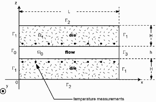
The steady laminar flow of an incompressible fluid is considered through an extrusion die ((---355----1) ), see . The velocity and the temperature fields are governed by the coupled equations of mass, momentum and energy, i.e.,
(---355--1)
(---355--2)
(---355--3)
(---355--4)
where,
(---355--5)
The following boundary conditions are considered for the velocity field:
| a. | At the inlet of the channel:
| ||||
| b. | At the outlet:
| ||||
The solution (T, u, w, p) of Equationequations (1)(---355--1) –Equation(7)
(---355--7-) is denoted as the Direct Problem Solution. When the pressure drop is fixed, and the temperature profiles T0(z) and Tp(x) are known, the Direct Problem Solution determines the temperature field within the extrusion die and the velocity field in the channel.
3. Inverse problem
3.1. Problem statement
For the inverse problem the inlet temperature profile T0(z) is regarded as being unknown and is to be estimated. Additional data are required for the solution. They consist of temperature measurements (---355----2) given by Ns sensors located at appropriate positions (xm, zp), m = 1, … , Ns, p = 1, 2 inside the extrusion die. Such measurements may contain random errors, but all the other quantities appearing in the direct problem Equationequations (1)
(---355--1) –Equation(7)
(---355--7-) are considered to be known with a sufficient degree of accuracy.
The velocity field is established from the entrance of the channel, hence only the energy equation has to be inverted. The inverse problem is formulated by introducing the following least squares function:
(---355--8)
where T(xm, zp; T0) are the temperatures computed from the Direct Problem Solution, at the measurement locations, by using an estimated inlet temperature profile T0(z).
Minimization of the function Equation(8)(---355--8) is achieved by constructing a sequence of approximations:
(---355----3) according to the CGM such that;
(---355--9)
(---355--10)
Where γn is the descent length and pn the descent direction, at iteration n.
Convergence of the above iterative procedure in minimizing quadratic functions like J(T0) is guaranteed in Citation[23]. To perform the iterations according to the Equationequations (9)(---355--9) –Equation(10)
(---355--10) , the gradient of the function
(---355----4) is needed.
3.2. Sensitivity problem
In order to develop the sensitivity problem equations, a variation εδT0 of the inlet temperature profile is considered, the resulting temperature is denoted T + = T(x, z; T0 + εδT0). The temperature sensitivity is then defined by:
(---355--11)
Developing the direct problem Equationequations (1)(---355--1) –Equation(7)
(---355--7-) for T(x, z; T0) and T(x, z; T0 + εδT0) and then subtracting the resulting expressions, leads to
(---355--12)
(---355--13)
(---355--14)
(---355--15)
(---355--16)
(---355--17)
where
(---355----5) is the solution of the direct problem Equationequations (1)
(---355--1) –Equation(7)
(---355--7-) .
3.3. Adjoint problem
In a first step, the variation δJ(T0) due to the variation δT0 of the inlet temperature profile is developed according to the definition:
(---355--18)
From Equationequation (8)
(---355--8) , we have:
(---355--19)
and from Equationequation (18)
(---355--18) , it comes:
(---355--20)
where,
(---355--21)
By definition, the gradient
(---355----6) satisfies:
(---355--22)
In order to compute the gradient (---355----7) , the Equationequation (20)
(---355--20) has to be transformed under this new form. It is convenient to introduce an adjoint variable Ψ and the Lagrangian L(Ψ, T, T0).
(---355--23)
and to take the variable Ψ solution of:
(---355--24)
According to this stationary condition, the following adjoint problem equations are obtained:
(---355--25)
(---355--26)
(---355--27)
(---355--28)
(---355--29)
(---355--30)
Together with the gradient equation:
(---355--31)
3.4. Conjugate gradient algorithm
The minimization algorithm by conjugate gradient (CG) involves the resolution of the three problems (direct, adjoint, and sensitivity) at each step of the iterative process. The overall CG algorithm may be summarized as follows:
| 1. | Choose an initial guess T0(z); | ||||
| 2. | Solve the direct problem given by Equationequations (1) | ||||
| 3. | Knowing the computed T(xm, zp; T0) and the measured temperatures | ||||
| 4. | Solve the adjoint problem; | ||||
| 5. | Compute the gradient | ||||
| 6. | Compute the direction of descent pn; If n = 0, Otherwise | ||||
| 7. | Solve the sensitivity problem with: δT0 = pn; | ||||
| 8. | Compute the step size:
| ||||
| 9. | Correct the inlet temperature profile:
| ||||
| 10. | Terminate the iteration when the convergence criterion is satisfied. Otherwise, | ||||
| 11. | Go to step 2. | ||||
4. Results and discussion
In order to examine the feasibility and then the accuracy of the inverse analysis for estimating the unknown inlet distribution temperature T0(z), by using the CGM. Two kinds of distribution are considered: a constant function and a smooth function. The effects of flow conditions and measurement errors are also analyzed.
4.1. Numerical solution of the direct problem
The computational technique used to solve the direct problem is based on a finite volume method (FVM) with discrete components of the governing mass, momentum, and energy equations. The staggered grid for Marker and Cell method (MAC) was employed to separate the governing equations. An augmented Lagrangian method Citation[22] is used to compute the solution of the coupling velocity–pressure Equationequations (1(---355--1) –Equation4)
(---355--4) . The grids are non-uniformly spaced in the z direction. The mesh spacing is taken smaller near the wall. The grids in the principal direction of flow are uniformly spaced (200 × 160). This distribution was dictated by the desire to capture the details of the viscous dissipation, because the temperature rise occurs in the region very near the wall and remains very low in the center of the channel die. The accuracy of the numerical solutions of the direct problem was studied in a previous article for a Newtonian and a pseudo-plastic fluid Citation[24]. These solutions were compared to analytical solutions; the comparison confirms that the selected grids are adequate. The same solver and grids are used to compute the adjoint and the sensitivity variables, because in the cases which are considered the highest variations of the sensitivity and the adjoint variables are also located very near the wall–polymer interface.
The problem is solved for a geometry illustrated in . The flow of a Newtonian polymer is studied in a parallelipedic channel. The height, the length, and the width of the channel are respectively h = 2 × 10⁻³ m, L = 0.2 m, and l = 20 × 10−3 m, and the solid wall thickness is H = 15 × 10−3 m. A coordinate system (see ) is considered such that Ox is the principal direction of the flow, z is the thickness coordinate, and y the width coordinate. It is assumed that the channel ratio l/h is sufficiently large such that a two-dimensional solution T(x, z) is valid at the medium plane (y = 0).
The properties of the polymer melt are taken as ρf = 1000 kg m−3, λf = 0.2 W m−1K−1 η = 1000 Pa s and Cpf = 2000 J kg−1 K−1. The pressure drop in the channel die is taken as Δp = 30 MPa and the specified temperature at the outer wall of the die is Tp(x) = 473 K. The thermal conductivity, density and heat capacity of the metallic wall are taken for this numerical study, as λw = 10 W m−1K−1, ρw = 7800 kg m−3 and Cpw = 400 J kg−1 K−1.
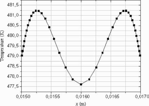
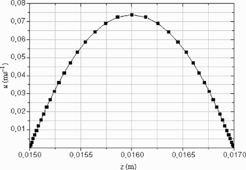
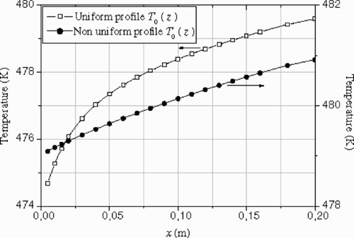
The polymer melt enters the extrusion die at x = 0 with a temperature profile T0(z). Two specific examples are considered: a non-uniform profile () in the first example and a uniform one in the second example. For both cases, the direct problem is solved to generate the velocity profile in the channel () and the measured temperature (---355----12) (). These data
(---355----13) are then used as ‘experimental’ data. In a first step, the data are considered without noise, and then a zero mean Gaussian noise is added to the data. For both experiments, the temperature measurements are given by 40 sensors located at zp, p = 1, 2 in the die wall; see . In practice, the sensor number will be less than 40, and then the inlet temperature profile T0(z) has to be parameterized in the following form:
(---355--35)
where the set of np basis functions ωk(z) is a priori given, with the parameter number less than the sensor number,
(---355----14) . This parameterization is not considered in this article.
4.2. Numerical results of the inverse problem
4.2.1. Example 1 – non-uniform inlet temperature profile-data without noise
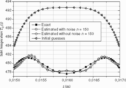
The inlet temperature profile () is chosen as the developed solution of a Newtonian fluid between two parallel isothermal walls. It is characterized by two peaks close to the die walls, which are due to high viscous dissipation Citation[16]. In order to examine the accuracy of the inverse analysis by using the CGM, two different temperature guesses (---355----16) are studied: a uniform profile and a parabolic one.
| 1. | Uniform guess The computation starts from the uniform guess Their magnitude remains small compared to that of | ||||
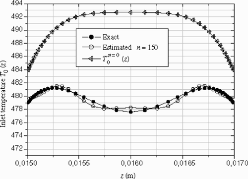
| 2. | Parabolic guess shows the comparison between the estimated inlet temperature profile and the exact one. For this case, the temperature inlet profile is represented quite well, as well as for the peak and near the wall, after 150 iterations. | ||||
Figure 5. Exact and estimated inlet temperature profiles for different iterations. Example 1 – data without noise.
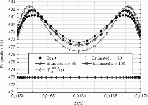
Figure 8. Exact and the estimate inlet temperature profile for 150 iterations. Example 1 – data without noise.
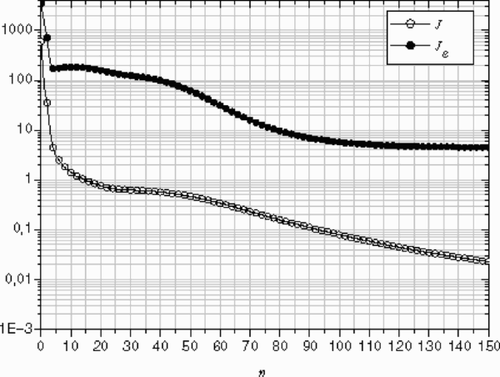
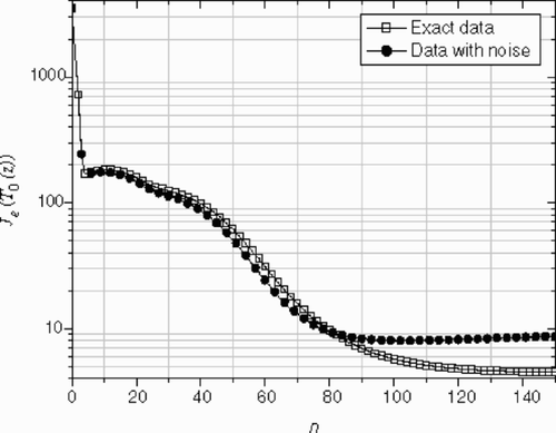
The norm Je of the deviation between the estimated inlet temperature (---355----19) and the exact temperature profile
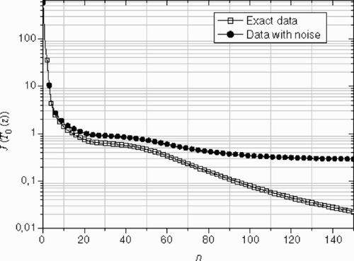
(---355----20) is computed at the inlet boundary of the channel die. The variability of Je and
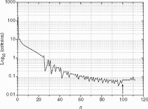
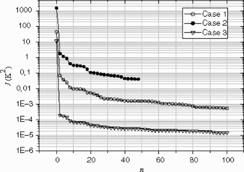
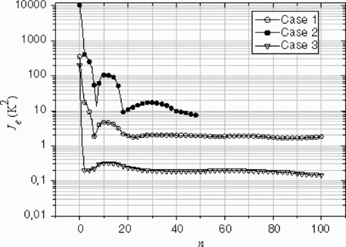
(---355----21) versus the iteration number can be seen on . After 100 iterations, no significant corrections to the estimated profile are observed (Je ≈ constant), while the criterion
(---355----22) is still decreasing.
4.2.2. Example 2 – uniform inlet temperature profile-data without noise
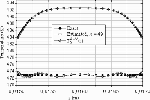
In polymer extrusion, the material is plasticated in an extruder before passing through the die for shaping purposes. The material is normally assumed to have a uniform temperature at the entrance of the die and the die is usually controlled at a given temperature. As such, it is hoped that the extrudate will have a uniform temperature. For this reason, we try here to estimate a uniform temperature profile. In order to check the algorithm, three typical initial guesses are considered:
| 1. | a uniform initial guess, | ||||
| 2. | a fourth-order polynomial with a maximum at the centerline, and | ||||
| 3. | a non-uniform profile with two peaks close to the die walls. | ||||
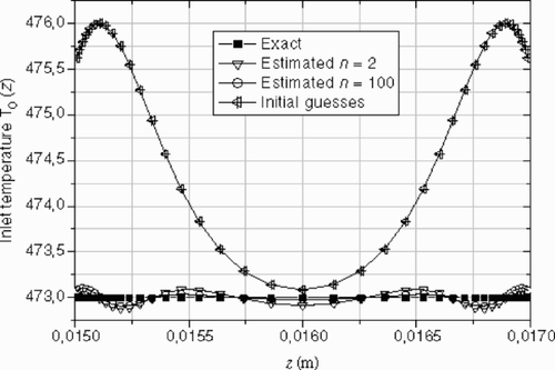
, , and show the reconstructed inlet temperature profiles. For the three cases, the estimated solutions oscillate around the exact one, and there are little differences between the exact and the estimated temperature at the centerline of the channel die, except near the walls where the viscous dissipation effects are important.
Figure 10. Exact and estimated inlet temperature profiles for different iterations: case (1) – Example 2.
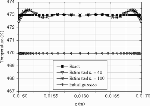
Figure 12. Exact and estimated inlet temperature profile for different iterations: case (3) – Example 2.
and show the effects of the initial guess on the convergence of the conjugate gradient algorithm. It is observed that the reconstruction of a uniform inlet temperature profile is more difficult than the previous non-uniform one. Due to the thermal history of the material in the extruder, a uniform temperature profile at the die entrance is not realistic.
It must be noted that for both the aforementioned examples, the residual principle is not applicable to stop the CG algorithm, because the data measurements are considered without noise.
4.2.3. Example 1 – non uniform inlet temperature profile-with noisy data
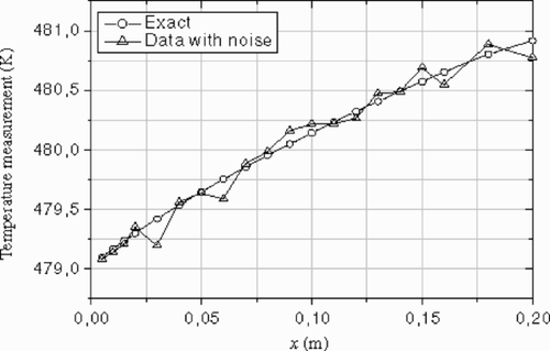
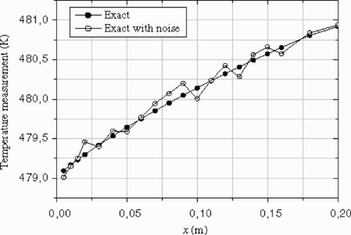
Since all experimental data are corrupted by noise, the challenge is to develop a stable algorithm, less susceptible to noise. To assess the effect of noisy data on the reconstructed inlet temperature profile, a zero mean Gaussian noise (σ = 0.1 K) was added to the exact data at sensor locations. The exact and the noisy data are shown in and .
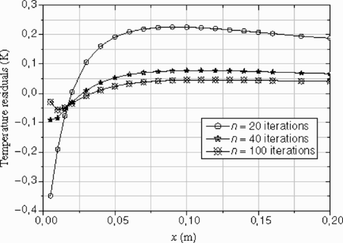
shows the difference between the reconstructed inlet temperature profiles obtained using exact and noisy data. The temperature peak was represented quite well by the inverse solution after 150 iterations. It can be seen that the estimated profile using noisy data is not symmetric. This confirms that the level of the noise is not exactly the same in the upper and lower wall (see and ). We remark that, due to the existence of noise in data, it is meaningless to proceed with the iterations to a very small criterion value ( and ), so for this case, the residual principle is applicable. After n = 150 iterations, the r.m.s of the residuals reaches the final value (---355----25) , this value is slightly less than the standard deviation of the noise. The optimal number of iterations given by the residuals principal
(---355----26) , is n = 90, as shown on and .
4.2.4. Sensitivity study
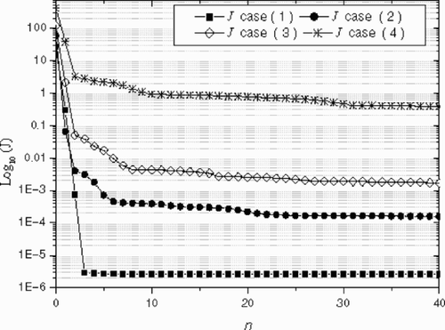
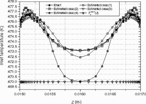
The effect of the flow conditions on the reconstructed inlet temperature profiles is observed by solving the inverse problem for different values of the pressure drop Δp: (case (1) Δp = 3 MPa, case (2) Δp = 10 MPa, case (3) Δp = 30 MPa, and case (4) Δp = 300 MPa). The inlet temperature profile to reconstruct is symmetric (like for the case studied in section 4.2.1). The initial guesses (---355----27) for each case is taken uniform, equal to 473 K.
shows the exact and estimated inlet temperature profile T0(z) and the variations of the output criterion J(T0(z)) are plotted on . The best results are obtained for the cases (2) and (3); the estimated profile is in excellent agreement with the exact solution except near the wall. In case (1), there are small deviations between the exact and the estimation at the centerline of the die channel. There are significant differences for the case (4), especially at the centerline of the channel. These results are confirmed by a sensitivity analysis.
Figure 20. Exact and reconstructed temperature profiles for each pressure drops – Sensitivity study.
These observations led us to investigate the influence of the flow and thermal conditions on the estimated inlet profiles. This study shows that the Cameron number, (---355----28) , can be used to characterize these conditions. The sensitivity of the measured temperature
(---355----29) to the inlet profile T0(z) is analyzed by considering the less favorable conditions where the variation δT0(z) is taken equal to zero everywhere except in the interval Δz located at the centerline of the channel (z = 0.016 m). The resulting sensitivity field θ(x, z), solution of Equationequations (12
(---355--12) –Equation17)
(---355--17) is calculated for each pressure drops Δp. , and show respectively the computed reduced values θ(x, z)/maxx,z|θ(x, z)| within the solid wall. It is observed that the maximum of the sensitivity θ(x, z) is always reached at the interface polymer/wall, and that its location on x-axis depends on the Cameron number.
The results obtained in correspond to ‘adiabatic’ flow conditions and Ca = 0.01. Only the sensors located at the exit of the channel (x ≥ 0.16 m) are sensitive to the variation δT0(z). Then the length of the channel is too short to estimate accurately the inlet temperature in the centerline of the channel.
corresponds to ‘transient’ flow conditions and Ca = 0.1. The effect of the variation δT0(z) appears clearly along the whole channel. The sensitivity is great enough to estimate the inlet temperature profile at the centerline of the channel.
corresponds to the ‘established’ flow conditions and Ca = 1.019. The average temperature of the flow remains constant, the sensitivity along the flow axis is close to zero as soon as x ≥ 0.06 m.
5. Conclusions
The classical conjugate gradient algorithm was developed for computing the numerical solution of the inverse heat transfer problem, which consists in the determination of the unknown inlet temperature profile of the melted polymer at the entrance of an extrusion die. The additional temperature data are measured in the solid wall of the die. The method was validated using exact and noisy data. The sensitivity analysis has shown that the most favorable conditions are characterized by the Cameron number value Ca = 0.1. These numerical results are encouraging and the applications of the method to the actual experimental data for a pseudo-plastic polymer are in progress.
Nomenclature
| 1. | Δp = Pressure drop, Δp = P0 − PL | ||||
| 2. | cp = Heat capacity | ||||
| 3. | η = Dynamic viscosity | ||||
| 4. | F = Source term of energy | ||||
| 5. | T0 = Inlet temperature | ||||
| 6. | pn = Direction of descent at iteration n | ||||
| 7. | J = Functional to be minimized | ||||
| 8. |
| ||||
| 9. | E = Temperature residuals | ||||
Subscripts
| 1. | m = Sensor location | ||||
| 2. | p = Sensor location | ||||
| 3. | e = Inlet die | ||||
| 4. | w = Wall | ||||
| 5. | f = Fluid | ||||
Superscripts
| 1. | n = Iteration number | ||||
| 2. | p = Pressure | ||||
| 3. | P0 = Inlet pressure | ||||
| 4. | PL = Outlet pressure | ||||
| 5. |
| ||||
| 6. |
| ||||
| 7. | T = Temperature | ||||
| 8. | n = Vector normal | ||||
| 9. | Ns = Number of sensors | ||||
Greek symbols
| 1. | γ = Shear rate | ||||
| 2. | γn = Step size at iteration n | ||||
| 3. | βn = Conjugate coefficient at iteration n | ||||
| 4. | Ψ = Adjoint variable | ||||
| 5. | θ = Sensitivity variable | ||||
| 6. | ρ = Mass density | ||||
| 7. | δ = Dirac delta function | ||||
| 8. | Ω = Spatial domain | ||||
Acknowledgments
The numerical computation were supported by the laboratory TREFLE, UMR 8508, Laboratoire interétablissements CNRS, ENSAM, ENSCPB, Université Bordeaux 1.
- Tadmor, Z, and Gogos, CG, 1979. Principles of Polymer Processing. New York. 1979.
- Alifanov, OM, 1994. Inverse Heat Transfer Problems. Berlin. 1994.
- Blanc, G, Raynaud, M, and Chau, TH, 1998. A guide for the use of function specification method for 2D inverse heat conduction problems, Revue Générale de Thermique 37 (1998), pp. 17–30.
- Ji, C-C, and Jang, H-Y, 1998. Experimental investigation in inverse heat conduction problem, Journal of Numerical Heat Transfer, Part A 34 (1998), pp. 75–91.
- Artyukhin, EA, Ivanov, GA, and Nenarokomov, AV, 1993. Determining the set of thermo physical properties of materials from unsteady-state temperature measurements, High Temperature 32 (2) (1993), pp. 199–202.
- Carvalho, G, and Silva Neto, AJ, 1999. "An inverse analysis for polymers thermal properties estimation". In: In: Proceedings of 3rd International Conference on Inverse Problems in Engineering: Theory and Practice. Port Ludlow, USA. 1999. p. pp. 495–500.
- Silva Neto, AJ, and Özisik, MN, 1992. Two-dimensional inverse heat conduction problem of estimating the time-varying strength of a line heat source, Journal of Applied Physics 71 (11) (1992), pp. 5357–5362.
- Su, J, and Silva Neto, AJ, 2001. Two-dimensional inverse problem of heat source strength estimation in cylindrical rods, Applied Mathematics and Modeling 25 (2001), pp. 861–872.
- Silva Neto, AJ, and Özisik, MN, 1994. "An inverse heat conduction problem of unknown initial condition". In: In: Proceedings of 10th International Heat Transfer Conference. Brighton, England. 1994.
- Muniz, WB, Campos Velho, HF, and Ramos, FM, 1999. A comparison of some inverse methods for estimating the initial condition of heat equation, Journal of Computational and Applied Mathematics 103 (1999), pp. 145–163.
- Beck, JV, Blackwell, B, and Clair, CR, 1985. Inverse Heat Conduction. New York. 1985.
- Alifanov, OM, Artyuhkin, EA, and Rumiantsev, SV, 1995. Extreme Methods for Solving Ill-Posed Problems with Applications to Inverse Heat Transfer Problems. New York. 1995.
- Liu, FC, and Özisik, MN, 1996. Estimation of inlet temperature profile in laminar duct flow, Inverse Problems in Engineering 3 (1996), pp. 131–141.
- Bokar, JC, and Özisik, MN, 1995. Inverse analyses for estimating the time varying inlet temperature in laminar flow inside a parallel plate duct, International Journal of Heat and Mass Transfer 38 (1995), pp. 39–45.
- Huang, CH, and Özisik, MN, 1992. Inverse problem of determining unknown wall heat flux in laminar flow trough a parallel plate, Numerical Heat Transfer, Part A 21 (1992), pp. 55–70.
- Machado, HA, and Orlande, HRB, 1998. Inverse problem for estimating the heat flux to a non-Newtonian fluid in a parallel plate channel, Journal of the Brazilian Society of Mechanical Sciences 20 (1998), pp. 51–61.
- Hsu, PT, Chen, CK, and Yang, YT, 1989. A 2-D inverse method for simultaneous estimation of the inlet temperature and wall heat flux in laminar circular duct flow, Numerical Heat Transfer, Part A 34 (1989), pp. 731–745.
- Huang, Ch.-H, and Chen, W-Ch., 2000. A three-dimensional inverse forced convection problem in estimating surface heat flux by conjugate gradient method, International Journal of Heat and Mass Transfer 43 (2000), pp. 3171–3181.
- Prud’homme, M, and Nguyen, TH, 1997. A numerical solution for the inverse natural convection problem, Numerical Heat Transfer, Part A 32 (1997), pp. 169–185.
- Gegadze, I, and Jarny, Y, 2002. An inverse heat transfer problem for restoring the temperature field in a polymer melt flow through a narrow channel, International Journal of Thermal Sciences 41 (6) (2002), pp. 528–535.
- Nguyen, KT, and Prystay, M, 1998. An inverse method for estimation of the initial temperature profile and its evolution in polymer processing, International Journal of Heat and Mass Transfer 42 (11) (1998), pp. 1969–1978.
- Aquilon online at:, http://www.enscpb.fr/master/Aquilon/.
- Ladson, LS, Mitter, SK, and Warren, AD, 1967. "The conjugate gradient method for optimal control problem". In: IEEE Transactions on Automatic Control. 1967. pp. 132–138, AC-12.
- Karkri, M, Jarny, Y, Mousseau, P, and Deterre, R, 2003. Thermique de l’écoulement d’un polymère pseudoplastique. 2003. p. pp. 667–672, In: Acte du congrès SFT2003 - Grenoble.
