Abstract
A shape reconstruction method for electrical resistance and capacitance tomography is presented using a level set formulation. In this shape reconstruction approach, the conductivity (or permittivity) values of the inhomogeneous background and the obstacles are assumed to be (approximately) known, but the number, sizes, shapes, and locations of these obstacles have to be recovered from the data. A key point in this shape identification technique is to represent geometrical boundaries of the obstacles by using a level set function. This representation of the shapes has the advantage that the level set function automatically handles the splitting or merging of the objects during the reconstruction. Another key point of the algorithm is to solve the inverse problem of finding the interfaces between two materials using a narrow-band method, which not only decreases the number of unknowns and therefore the computational cost of the inversion, but also tends to improve the condition number of the discrete inverse problem compared to pixel (voxel)-based image reconstruction. Level set shape reconstruction results shown in this article are some of the first ones using experimental electrical tomography data. The experimental results also show some improvements in image quality compared with the pixel-based image reconstruction. The proposed technique is applied to 2D resistance and capacitance tomography for both simulated and experimental data. In addition, a full 3D inversion is performed on simulated 3D resistance tomography data.
1. Introduction
Electrical resistance and capacitance tomography (ERT and ECT) are low frequency imaging modalities Citation1,Citation2. ERT has great potential for medical and industrial applications and ECT has found various applications related to industrial process monitoring. There are many similarities between these two techniques in terms of the forward and the inverse problems, so they can be studied in the same manner Citation3,Citation4, although there are a few minor differences. ERT and ECT are two major members of the electrical imaging family, the term electrical impedance tomography (EIT) is generally used for the extension of ERT to complex conductivities. In this article, we study a shape based method to solve the inverse problem of ERT and ECT for two-phase materials using a level set method. In an analogous fashion, a multiple level set method can be applied to three or more phase materials, but in this article we concentrate on two phase materials and leave the more general case to future research. For many industrial process monitoring applications of ERT and ECT, the material has two distinct homogeneous phases with relatively smooth boundaries. In ERT one seeks to image the conductivity from external measurements of the potential using multiple field patterns at low frequency as a result of the excitation at the external boundary. In ERT dielectric effects and magnetic fields are considered to be negligible. In ECT, on the other hand, the object is assumed to be insulating. Using a system of conducting electrodes, each excited in turn with a known potential, charge displacements are measured at each of the non-excited electrodes. One then attempts to image the spatial variation of permittivity. A system of grounded electrodes is used to make the system insensitive to electrostatic charges in the region exterior to the sensor. Another promising application of ERT is medical imaging, where currents of low intensity are used in order to image electrical properties of the human body. We will present in this article numerical examples that demonstrate the use of a level set formulation for some general examples. The general framework can be used to be implemented for an application for both medical and industrial imaging problems.
Recently, shape-based reconstruction techniques have become more popular in ERT. For example, shape reconstruction has been studied in Citation5, monotonicity based shape reconstruction in Citation4, linear sampling type methods in Citation6, Citation7, the use of Mittag–Leffler's functions in Citation8, the use of a Mumford–Shah functional in Citation9, and level set methods in Citation10. Most of these schemes were applied to simulated data. The linear sampling method was applied to real measurement data in ERT reported in Citation11. The results presented in this article demonstrate the feasibility of the level set method for real applications. This shape reconstruction algorithm is a nonlinear inversion scheme, which makes use of a numerical shape propagation technique, the so-called level set technique, which originally was developed for the modelling of moving interfaces Citation12–14. There have been extensive studies using a level set technique for shape reconstruction in electrical and electromagnetic imaging (see for example Citation15–17). The level set method is well-suited for this application since it is able to easily accommodate topological changes of the boundaries. The shapes are given as the zero level set of a higher dimensional function. If we change this higher dimensional function (called the ‘level set function’), for example by adding an update, we move the shapes accordingly. In particular, topological changes are performed automatically in this way. The basic idea in this article is to calculate these updates (using an optimization approach), such that the shapes are deformed to reduce a given cost functional. For alternative approaches and examples for level set reconstructions in the literature (mainly applied to simulated data) we refer for example to Citation10,Citation16,Citation17. A 3D level set reconstruction for ERT has been presented in Citation18. The main contribution of this article is to apply a narrowband level set method to the electrical imaging and comparing the results with standard image reconstruction method. In this article we show that the proposed method outperforms the standard image-based method in terms of image quality as well as computational time.
2. Forward problem
The forward problems in both ECT and ERT consist of an electrostatic approximation to Maxwell's equations. The fundamental unknown of the forward problem is the electric potential u. Given the conductivity distribution (γ =σ) in ERT or the permittivity distribution (γ =ϵ) in ECT, u is calculated in the domain of interest Ω by solving the partial differential equation
(------126398--1)
with suitable boundary conditions on ∂Ω, which are further specified below.
2.1. Forward problem in ERT
The forward problem in ERT is to predict the voltage on the sensing electrodes given applied current to the exciting electrodes. The electric current applied to the excitation electrodes and the potential between electrodes are measured using phase sensitive detection and a differential amplifier.
Using metallic electrodes in contact with an aqueous solution, the boundary conditions are described by the complete electrode model (CEM). With current Ik on electrode Ek having contact impedance zk, the complete electrode boundary conditions Citation1 are
where Vk is the constant voltage on the kth electrode, and σ (∂ u /∂ n) = 0 on the boundary where there is no electrode.
The finite element method (FEM) is used for discretizing the forward ERT and ECT problems. To solve the forward ERT/ECT problem in 2D, we use the software package EIDORS-2D Citation1. Similarly, we use EIDORS-3D Citation19 in order to solve the forward problem of 3D ERT. In order to improve the speed of the forward solver, we modified EIDORS-3D by implementing an algebraic multigrid (AMG) method for the linear system of equations arising from the FEM model Citation20. With this, we then employ the level set scheme as described in this article to reconstruct 3D shapes.
2.2. Forward problem in ECT
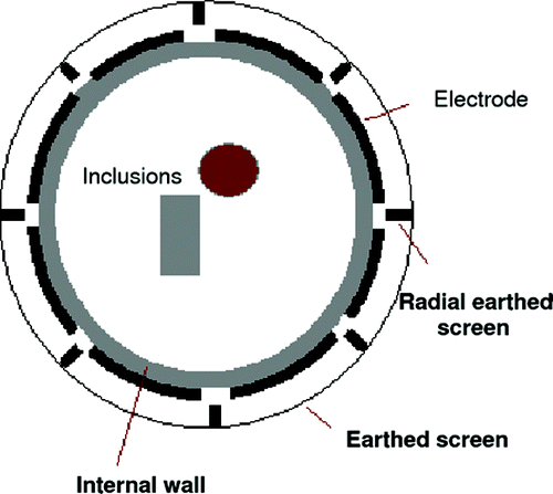
Potential applications of ECT include monitoring of oil and gas mixtures in oil pipe lines and flow measurement in pneumatic conveying (see for example Citation21). ECT sensors measure the dielectric permittivity of a sample. A typical ECT sensor comprises a circular array of 8 or 12 plate electrodes, mounted on the outside of a nonconducting pipe, surrounded by an electrical shield. For metal-walled vessels, the sensor must be mounted internally, using the metal wall as the electrical shield. Additional components include radial and axial guard electrodes, of which many configurations have been tried, to improve the quality of the measurements and hence images. It is not necessary for the electrodes to make physical contact with the specimen, so they can be used on conveyor-lines, or externally mounted to plastic piping to reduce the risk of contamination. In a typical measurement pattern, the voltage is applied to one electrode and the rest of the electrodes are grounded. A typical ECT sensor is shown in . The electric charge is then measured as electric current from the electrodes.
The forward problem in ECT is the prediction of the collected charge on the sensing electrodes given a permittivity distribution and the electric potential on the exciting electrodes. Mathematically, this amounts to solving a discretized form of (1). The boundary condition here is to apply the potential vk to the active electrode and the potential zero to the remaining electrodes. This is modelled by the Dirichlet boundary condition
where Vd is the region containing the field (possibly an infinite region) and Ek is the (active) kth electrode, held at the constant potential vk, usually attached at the surface of an insulator. The electric charge on the (sensing) lth electrode is then given by
(------126398--2)
where ϵ is dielectric permittivity and n is the inward normal on the lth electrode.
For ECT we use a forward problem solver, which has been implemented for a nonlinear ECT image reconstruction earlier as reported in Citation22.
2.3. Sensitivity formula
We use the linearized sensitivity of the voltage measurement to a change in permittivity for ECT and to the change in electric conductivity in ERT. This type of perturbation calculation, which mathematically amounts to calculating the Fréchet derivative of the measurement data with respect to permittivity and conductivity, is standard in a broad class of inverse problems (see for example Citation3). A treatment of this linearization for full Maxwell's equations can be found for example in Citation23. At each point in the domain the calculated sensitivity is essentially proportional to the inner product of two electric field vectors at the given location. In particular, we have for ERT
(------126398--3)
and for ECT
(------126398--4)
Here, Ω is the region containing the perturbation. The index k indicates here the actual source position, and the index l, the actual measurement position. In more detail,
and
are the calculated electric fields of the forward problem when electrodes k and l are excited, respectively. This sensitivity formula results in an efficient method for the assembly of the Jacobian matrix. In the FEM model introduced in the previous section, we have
.
3. Inverse medium problem
Pixel (voxel)-based image reconstruction in ECT and ERT is an inverse medium problem. The most commonly used inversion method is the regularized Gauss–Newton method (see for example Citation3). This scheme essentially tries to find a distribution for the parameter γ (conductivity or permittivity), which minimizes
(------126398--5)
Here γp is an a priori guess for the material distribution and F is the forward map. The update formula in the corresponding nonlinear iteration is then
(------126398--6)
Here Jn is the Jacobian calculated with γ n being the conductivity in ERT and permittivity in ECT. The vector M contains the physically measured data (measured voltages in ERT, capacitance data in ECT), and the vector F( γn ) contains the predicted measurements using the numerical forward model with the conductivity or permittivity γ n. λ is the step-size for the current update. The matrix L is a regularization matrix. Typically, L is a first-order difference operator between neighbouring pixels/voxels, which penalizes extreme changes in the parameters. This way, it removes the instability in the reconstruction at the cost of producing artificially smooth images. Alternatively, it can also be chosen as a multiple of the identity, which avoids this smoothing effect but might not be sufficient for stabilizing the inversion. In our pixel/voxel-based inversions, we will take L as a discretized first-order difference operator approximated by finite differences: Lij=-1 for i ≠ j when two elements are neighbours (sharing at least one node) and Lii=-Σ jLi j , i ≠ j.
4. Inverse interface problem using level sets
Compared to the more typical pixel (voxel)-based reconstruction schemes, the shape reconstruction approach has the advantage that a priori information about the high contrast of the inclusions is incorporated explicitly in the modelling of the problem. With this technique, a more accurate reconstruction of the high-contrast objects can be achieved than is possible with the more traditional reconstruction schemes. This is because most regularization schemes for the traditional methods, which are necessary for stabilizing the inversion, have the side-effect of artificially smoothing the reconstructed images. Therefore, these schemes are not well-suited for reconstructing high contrast objects with sharp boundaries.
In order to arrive at a robust and efficient shape-based inversion method, a powerful technique needs to be incorporated for computationally modelling the moving shapes. We have chosen to use the level set technique Citation12,Citation16 to describe the changing shapes, since this method is able to easily model topological changes of the boundaries. In this technique, the shapes which define the boundaries, are represented by the zero level set of a level set function Ψ. If D is the inclusion with conductivity (or permittivity) γ int embedded in a background with conductivity (or permittivity) γ ext, the boundary of the inclusion, which is also an interface between two materials, is given by the zero level set
(------126398--7)
where the image parameter at each point r is
(------126398--8)
If we change this level set function for example by adding an update, we move the shapes accordingly. This relation is used in the level set technique when constructing updates to a given level set function such that the shapes are deformed in a way which reduces a given cost functional.
In general, one possibility for moving the shapes in order to solve our shape reconstruction problem is to introduce a shape evolution of the level set function, which is described by a Hamilton–Jacobi equation
(------126398--9)
Here β(t) is a velocity function of evolving contours in their outward normal direction, which is usually chosen to point into the gradient direction of the cost functional in each time step of the evolution. This approach leads to a ‘steepest descent flow’ for the inversion. See for example Citation16,Citation24,Citation25.
However, our approach will be slightly different. We want to combine well-known and very efficient optimization techniques (in particular the general idea of a Gauss–Newton approach described in the previous section) with our newly developed shape-based inversion approach. Using optimization strategies for the shape inversion as an alternative to a shape evolution approach was already suggested in the early paper by Santosa Citation17. In order to mathematically derive this new optimization scheme for our situation, we will denote the mapping which assigns to a given level set function ΨD the corresponding parameter distribution γ by γ =Φ (Ψ D). The parameter distribution γ has the same meaning as in the traditional Gauss–Newton inversion scheme. The only difference is that in the shape-based situation it is considered as having only two values, namely an ‘inside’ value and an ‘outside’ value. (Certainly, this assumption can be generalized by allowing these ‘inside’ and ‘outside’ values to be smoothly varying functions, separated by the interface. We will not consider this extension here.) However, in our new approach, it will only be an intermediate parameter, linking the data finally to the new basic unknown of the inverse problem, namely the level set function ΨD.
Having defined this mapping Φ, we can now replace the iterated parameter γn by γ n=Φ . Instead of the forward mapping F(γ) we need to consider now in the new Gauss–Newton type approach the combined mapping
If we perturb the latest best guess for the level set function Ψ by some small correction δΨ, the linearized response in the data will be
(------126398--10)
according to the chain rule. In Citation17, Santosa has shown that the linearized infinitesimal response in the parameter due to a perturbation in the level set function can be formally described as
(------126398--11)
where δ ∂ D is the Dirac delta function concentrated on the boundary of the latest best guess for the shape D. The singular nature of the Dirac delta function which is involved in this expression causes some mathematical complications when directly applying this expression to the Gauss–Newton update. (In mathematical terms, the main difficulty is that the Dirac delta distribution is not a member of the usually employed Hilbert space L2.) However, these technical subtleties can be circumvented by approximating the Dirac delta function by a smeared-out version of it (which, in fact, will now be a member of the space L2). We will use for this purpose the function
where χ ρ is the indicator function of a small narrow band of half-width ρ centred at ∂D, and Cρ is the corresponding normalization factor. (See also the interesting discussions of regularized delta functions for related applications in Citation26,Citation27.) With this approximation, we get
(------126398--12)
It is convenient to further approximate ∇ Ψ |≈ c1 with some constant c1, which usually is justified if we rescale our level set function after each step, or even recalculate it as a signed-distance function (in which case we have ∇ Ψ |=1). We finally arrive at
(------126398--13)
with the constant
We denote the discretized form of Φ ′[Ψ ] by K, and the Jacobian of G by B. Then, the new Gauss–Newton update is
(------126398--14)
with (suppressing the iteration index n)
(------126398--15)
Here Ψp in the regularization term corresponds to some a priori knowledge of the level set function. Equation (14) is completely analogous to our previous pixel/voxel-based Gauss–Newton update (6). Notice also that (15) implies that BTB can be restricted to be defined only on the narrow band, since both K and KT contain discretized versions of χ ρ (x).
There are two parameters (λ and α) to be tuned in this level set formulation. The optimal choice of these two parameters depends on the mesh density, the conductivity (or permittivity) contrast and the initial guess. The relaxation parameter λ has mainly the meaning of a ‘step-size’ parameter: it essentially determines the magnitude of changes in the shape in a given update. The effect of the regularization parameter α depends on the choice of the regularization operator L. Using the identity matrix for L, this regularization parameter has a positive effect on the stability of the inversion without smoothing out the level set function too much. When a first order difference operator for L is used instead, the effect will be a smoothing of the level set function. In this case, the larger the α we choose, the smoother the final level set function tends to be. In particular, high frequency components of the boundaries of our shapes will be suppressed by this technique. The optimal choice of the parameter α will depend on several factors, for example on the expected complexity of the correct shape of each inclusion, the spatial position of the different inclusions with respect to each other and with respect to the electrodes, and on the initial guess. If α is chosen to be too large, it is more difficult for the scheme to split objects in order to perform topological changes. This means, resolution may suffer when α is chosen too large, and the scheme might have difficulties to detect smaller objects which are at a certain distance from inclusions with a more dominant effect on the data. In our numerical experiments shown in the following section, we will choose L to be the identity operator. This allows us to better separate different objects from each other. On the other hand, by this choice the boundaries of our reconstructed shapes are allowed to show some ‘roughness’ in the final reconstructions, as can be observed in the figures shown in the following section.
An interesting question is also how to choose the a priori level set function Ψp in (14). Since the level set function has a different significance for the reconstruction than the parameter distribution itself, different choices might be required here. For example, just putting an arbitrary initial guess Ψ0 as Ψp might not be the best solution since the level set function usually is ‘meaningless’ outside a small neighbourhood of the zero level set. On the other hand, if the initial guess Ψ0 for the level set function has been calculated by using an independent and fast preprocessing tool (as e.g. in Citation15,Citation28,Citation29), it could be used instead as a good choice for Ψp. We will in our reconstructions simply apply the operator LTL (a multiple of the identity) to the latest best guess Ψn, which amounts to putting Ψ p=0.
5. Results
The pixel/voxel based image reconstruction results in this section are all based on the standard regularized Gauss–Newton method using Tikhonov regularization as described in Citation3.
5.1. 2D ERT reconstructions from noisy simulated data
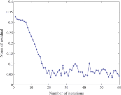
The first numerical example is a simple but representative example of a 2D cross section of a pipe, which may be used in industrial process tomography. There are 12 electrodes equally spaced along the length of the pipe, 6 electrodes on each side. We use an opposite current pattern for this application. In , the reconstruction of inclusions with conductivity of 8 Sm−1 embedded in a background with conductivity 1 Sm−1 is shown. The data was generated synthetically using our forward model, and Gaussian noise with S.D. of 1% of the largest measurement was added to these simulated measurement data. In order to avoid the so-called ‘inverse crime’, we used different meshes, namely a triangular mesh for the FEM model for calculating the simulated data, and a uniform grid mesh (a 100 by 100 grid) during the level set reconstruction. The level set method was able to identify the position and a relatively accurate shape of the inclusion. shows the evolution of the norm of the residuals during the shape reconstruction process.
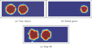
In the next example (), we attempt to reconstruct two objects which are located relatively close to each other. It is interesting to see that the two objects could be clearly separated in the level set-based reconstruction. The inclusions have a conductivity of 25 Sm−1 and the background medium has a conductivity value of 1 Sm−1. With a standard regularized pixel-based solution, it is hard to separate these two objects. The initial guess was a circle in the far right of the pipe. With a choice of the regularization parameter to be α =10-3, we were able to reconstruct after 120 iterations one of the disc-shaped inclusions (on the left hand side), but it takes many more iterations to also reconstruct the second one. When we choose the regularization parameter to be smaller, namely α =10-6, we successfully reconstruct after 48 iterations the two objects as shown in .
5.2. 3D ERT reconstructions from noisy simulated data
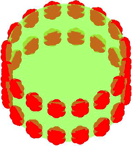
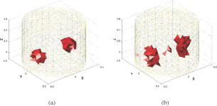
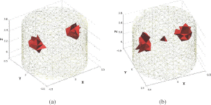
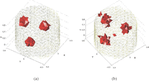
shows the electrode arrangement for a 32-electrode ERT system. There are two planar circles of 16 electrodes each. The adjacent current pattern has been used for excitation. To solve the forward problem we use a finite element scheme with 9568 tetrahedral elements. Again, in order to avoid the ‘inverse crime’, we used different grids for generating the data and for the reconstruction. In addition, 2% Gaussian noise were added to the simulated data.
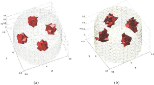
Figures show the true shapes and the reconstructed shapes for different 3D ERT examples. In all these examples, the background has a conductivity of 1 Sm−1 and the inclusions have a conductivity value of 20 Sm−1.
5.3. ERT reconstructions from experimental data
shows reconstructions from experimental data for different examples using both the level set-based shape reconstruction scheme and a standard Gauss–Newton pixel-based reconstruction scheme Citation3. In all situations, cylindrical 3D objects were used for gathering the data experimentally. Then, our 2D reconstruction methods (pixel-based and shape-based) were applied to these experimental data to recover a 2D cross section of the original profile. The following description will be in terms of the 2D cross sections.
Figure 10. Comparison of level set reconstructions with pixel-based Gauss–Newton reconstructions for ERT experimental data. The left column shows the real objects, the central column the pixel-based reconstructions, and the right column the shape-based reconstructions using level sets.
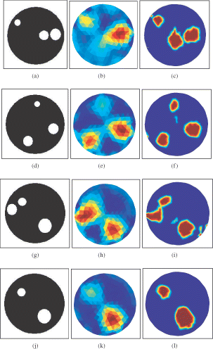
The first example shows three different circular objects, two of them being relatively close to each other. The second example shows three different circular objects which are all well-separated from each other. The third example shows three different circular objects of which two are close to each other and near to the electrodes. Finally, the fourth example shows two circular objects. The measurement data consisted of 104 voltage measurements from adjacent current patterns and from a 16-electrode ERT system with the diameter of the electrode ring being 30 cm. The number of iterations used in the pixel-based reconstructions was always 4, and the number of iterations for the level set method was 24, 15, 27, 15, respectively, for these four test examples. The initial guess for the shape reconstructions was always a disc centred at (0,0) with a diameter of 6 cm.
5.4. ECT reconstructions from experimental data
shows reconstructions for some situations using experimental ECT data. The same data have been used previously in a different reconstruction method in Citation2. To evaluate and compare our level set-based and pixel-based algorithms, experimental data was used from an 8-electrode sensor of 84 mm diameter. The measurement electrodes were 10 cm long (in the third dimension, not captured by our 2D images) and were mounted symmetrically on the outside boundary of an insulating pipe. Then, 28 measurement data were taken and used in the reconstructions. In the first example (see ), a ring of Perspex with a circular object (also Perspex, 26 mm in diameter) in the centre is considered. In the second example, two circular objects (both Perspex, 32 mm in diameter) are considered. The third example consists of a single ring of Perspex with a cylindrical hole in its centre (air with diameter 26 mm), whereas in the fourth example one cylindrical object (Perspex, 32 mm in diameter) is positioned near the wall. The Perspex material used for all of these objects has a relative permittivity of 1.8. The background is always ‘free space’ with a relative permittivity of 1. The number of iterations for the pixel-based reconstructions was 3 in all cases, and the number of iterations for the level set reconstructions was 25, 48, 16, 17, respectively.
Figure 11. Comparison of level set reconstructions with pixel-based Gauss–Newton reconstructions for ECT experimental data. The region of interest is the interior of the pipe. The left column shows the real objects, the central column the pixel-based reconstructions, and the right column the shape-based reconstructions using level sets.
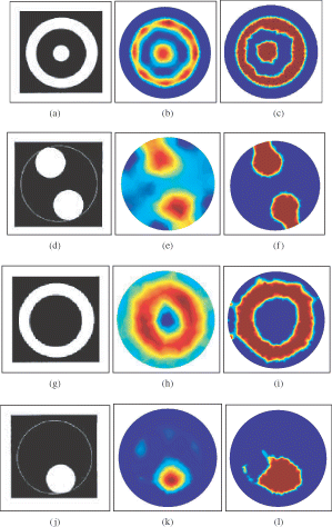
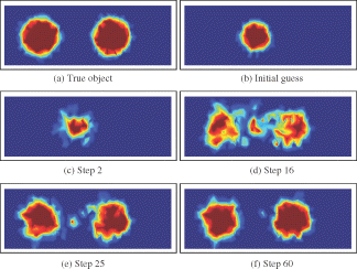
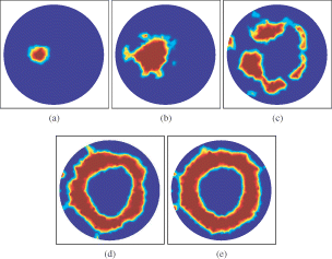
In we finally show, in more detail, the evolution of the shape for the situation of the third row in (example (g)), in order to demonstrate the behaviour of our level set reconstruction scheme in this difficult situation of reconstructing a ring-like structure starting from a small disc. Notice that during the evolution, the shape is quite fractured, whereas in the final reconstruction, the shape has recombined the individual parts into a fairly complete ring-like structure.
6. Conclusion
We have presented a level set-based method for shape reconstruction in ECT and ERT. In situations where the unknown objects can be represented by shapes with a high contrast to the background, shape-based identification is much better adapted to the problem than a pixel-based reconstruction scheme. A pixel-based scheme can be used in order to find quickly a good initial guess for the shape evolution. However, when continuing a pixel-based inversion for more than a few iterations, the convergence to the high-contrast obstacles becomes very slow due to the smoothing effect of most regularization schemes. When a shape-based inversion scheme is used instead, convergence is extremely fast and gives very good results.
The performance of our shape-based inversion scheme in practical situations has been demonstrated in this article by presenting shape reconstructions from real experimental ECT and ERT data. The improvements of this method compared to more traditional pixel-based reconstructions are indicated by the presented results. Separating two objects which are close to each other is typically a hard task in pixel-based ERT imaging. Here, our scheme was able to successfully separate two nearby objects from each other using the level set-based method. Moreover, we have shown that the level set formulation can recover objects with a high contrast to the background, which is another difficulty in more traditional pixel-based inversion schemes.
An interesting side-effect of our specific scheme is the restriction of the basic operators to be defined only on the narrow band around the most recent best guess. This reduces the dimension and the complexity of the operators significantly. In particular, the condition number of the corresponding Jacobian tends to be much better than in the corresponding pixel-based inversion scheme, simply because the sizes of the involved matrices are smaller. Moreover, most operations on these smaller-sized matrices can be performed more rapidly than in a full Gauss–Newton inversion. Therefore, the individual update is less expensive than in the pixel-based inversion scheme. That makes the technique attractive for large scale inversion problems in particular. Finally we have found that, with a suitable choice of the step-size (for example using a line-search technique), the total number of iterations can be reduced as well.
Acknowledgements
The experimental data for ERT was the data provided to validate the EIDORS-2D software Citation1. The experimental data for ECT has been provided by Dr W.Q. Yang and colleagues (published in Citation2) from the industrial process tomography group at the University of Manchester. The work was partially supported by EPSRC grants GR/R64278 and GR/R93612.
References
- Vauhkonen, M, Lionheart, WRB, Heikkinen, LM, Vauhkonen, PJ, and Kaipio, JP, 2001. A MATLAB package for the EIDORS project to reconstruct two-dimensional EIT images, Physiological Measurement 22 (2001), pp. 107–111.
- Yang, WQ, Spink, DM, York, TA, and McCann, H, 1999. An image-reconstruction algorithm based on Landweber's iteration method for electrical-capacitance tomography, Measurement Science and Technology 10 (1999), pp. 1065–1069.
- Lionheart, WRB, Reconstruction algorithms for permittivity and conductivity imaging. Presented at Proc. 2nd World Congress on Industrial Process Tomography. Hannover, Germany, 2001.
- Tamburrino, A, Rubinacci, G, Soleimani, M, and Lionheart, WRB, A noniterative inversion method for electrical resistance, capacitance and inductance tomography for two phase materials. Presented at Proc. 3rd World Congress on Industrial Process Tomography. Banff, Canada, 2003.
- Kolehmainen, V, Arridge, SR, Lionheart, WRB, Vauhkonen, M, and Kaipio, JP, 1999. Recovery of region boundaries of piecewise constant coefficients of an elliptic PDE from boundary data, Inverse Problems 15 (1999), pp. 1375–1391.
- Brühl, M, and Hanke, M, 2000. Numerical implementation of two noniterative methods for locating inclusions by impedance tomography, Inverse Problems 16 (2000), pp. 1029–1042.
- Brühl, M, 2001. Explicit characterization of inclusions in electrical impedance tomography, SIAM Journal on Mathematical Analysis 32 (2001), pp. 1327–1341.
- Ikehata, M, and Siltanen, S, 2004. Electrical impedance tomography and Mittag-Leffler's function, Inverse Problems 20 (2004), pp. 1325–1348.
- Rondi, L, and Santosa, F, 2001. Enhanced electrical impedance tomography via the Mumford-Shah functional, ESAIM: COCV 6 (2001), pp. 517–538.
- Chan, TF, and Tai, XC, 2004. Level set and total variation regularization for elliptic inverse problems with discontinuous coefficients, Journal of Computational Physics 193 (2004), pp. 40–66.
- Hanke-Bourgeois, M, and Brühl, M, 2003. Recent progress in electrical impedance tomography, Inverse Problems 19 (2003), pp. S65–S90.
- Osher, S, and Sethiasn, J, 1988. Fronts propagation with curvature dependent speed: algorithms based on Hamilton-Jacobi formulations, Journal of Computational Physics 56 (1988), pp. 12–49.
- Osher, S, and Fedkiw, R, 2003. Level Set Methods and Dynamic Implicit Surfaces. New York: Springer; 2003.
- Sethian, J, 1999. Level Set Methods and Fast Marching Methods, . Cambridge, UK: Cambridge University Press; 1999.
- Dorn, O, Miller, EL, and Rappaport, CM, 2000. A shape reconstruction method for electromagnetic tomography using adjoint fields and level sets, Inverse Problems 16 (2000), pp. 1119–1156.
- Litman, A, Lesselier, D, and Santosa, F, 1998. Reconstruction of a two-dimensional binary obstacle by controlled evolution of a level-set, Inverse Problems 14 (1998), pp. 685–706.
- Santosa, F, 1996. A level-set approach for inverse problems involving obstacles, ESAIM: Control, Optimization and Calculus of Variations 1 (1996), pp. 17–33.
- Boverman, G, Khames, M, and Miller, EL, 2003. Recent work in shape-based methods for diffusive inverse problems, Review of Scientific Instruments 74 (2003), pp. 2580–2582.
- Polydorides, N, and Lionheart, WRB, 2002. A MATLAB based toolkit for three-dimensional electrical impedance tomography: a contribution to the EIDORS project, Measurement Science and Technology 13 (2002), pp. 1871–1883.
- Soleimani, M, Powell, CE, and Polydorides, N, 2005. Improving the forward solver for the complete electrode model in EIT using algebraic multigrid, IEEE Transaction on Medical Imaging 24 (2005), pp. 577–583.
- Dyakowski, T, Jeanmeure, LFC, Zimmerman, WB, and Clark, W, 2002. Direct flow-pattern identification using electrical capacitance tomography, Experimental Thermal and Fluid Science 26 (2002), pp. 763–773.
- Soleimani, M, and Lionheart, WRB, 2005. A nonlinear image reconstruction for electrical capacitance tomography using experimental data, Measurement Science and Technology (2005), (in press).
- Somersalo, E, Isaacson, D, and Cheney, M, 1992. A linearized inverse boundary-value problem for Maxwell equation, Journal of Computational and Applied Mathematics 42 (1992), pp. 123–136.
- Burger, M, 2001. A level set method for inverse problems, Inverse Problems 17 (2001), pp. 1327–1355.
- Ito, K, Kunisch, K, and Li, Z, 2001. Level-set function approach to an inverse interface problem, Inverse Problems 17 (2001), pp. 1225–1242.
- Leitao, A, and Scherzer, O, 2003. On the relation between constraint regularization, level sets, and shape optimization, Inverse Problems 19 (2003), pp. L1–L11.
- Zhao, HK, Chan, T, Merriman, B, and Osher, S, 1996. A variational level set approach to multiphase motion, Journal of Computational Physics 127 (1996), pp. 179–195.
- Dorn, O, 2002. Shape reconstruction in scattering media with voids using a transport model and level sets, The Canadian Applied Mathematics Quarterly 10 (2002), pp. 239–275, Also MSRI Preprint, http://www.msri.org/publications/preprints/online/2002-002.html.
- Soleimani, M, Aykroyd, RG, Freear, S, Lionheart, WRB, and Podd, F, Multi-modal data fusion for enhanced imaging applied to 3D ERT with Ultrasound time of flight data. Presented at Proceedings of 4th World Congress on Industrial Process Tomography. Aizo, Japan, 2005, (in press).
