Abstract
An inverse blade design method applicable to two- and three-dimensional inviscid and viscous flow in turbomachinery cascades is presented and is applied to design cascades in two-dimensional viscous flow. The pressure distribution along the blade surfaces is prescribed and is reached by modifying the initial guess of the blade geometry. The geometry modification is computed from a virtual velocity distribution derived from the difference between the current and the target pressure along the blade surfaces. The inverse method is implemented into and is consistent with the unsteady Reynolds-averaged Navier-Stokes (RANS) equations where an arbitrary Lagrangian–Eulerian (ALE) formulation on a moving and deforming grid is used. The grid velocities are determined from the space conservation law (SCL), which ensures a fully conservative computational procedure. The unsteady RANS equations are discretized using a cell-vertex finite volume method and the time accuracy is achieved using a dual time stepping scheme. An algebraic Baldwin–Lomax model is used for turbulence closure. The design method is first validated, and then its robustness, flexibility and usefulness are demonstrated on the redesign of recent compressor and turbine blade geometries used in modern gas turbine engines.
Nomenclature
| a | = | speed of sound |
| c | = | axial chord length |
| cp | = | specific heat in constant pressure |
| E | = | Energy |
| f, g | = | flux vectors |
| k | = | thermal conductivity |
| LE/TE | = | leading/trailing edge |
| n | = | surface vectors |
| p | = | static pressure |
| Pr | = | Prandtl number |
| q | = | heat flux vector |
| Re | = | Reynolds number |
| SS/PS | = | Suction/Pressure side of the blade |
| u,v | = | Cartesian velocity components |
| V | = | surface normal velocity |
| t | = | time |
| w | = | vector of flow variables |
| α | = | relaxation factor |
| ρ | = | density |
| μ | = | viscosity |
| σ | = | stress tensor |
| θ | = | surface angle |
| Ω | = | volume |
Subscripts
| k | = | cell face |
| g | = | grid |
| c | = | convective |
| v | = | diffusive |
Superscripts
| d | = | design |
| e | = | edge |
| n | = | new time step |
| o | = | old time step |
| r | = | relaxation |
| s | = | smoothing |
| v | = | virtual |
1. Introduction
As computational fluid dynamics (CFD) is maturing, numerical flow simulation is regularly used to analyze the flow in blade row passages of modern gas turbine engines. However, aerodynamic design methods using main stream CFD methods have not progressed as fast as analysis methods. Designers usually adopt a direct (analysis) approach, evaluating the performance of an actual geometry and modify it according to either empirical rules or their own experience to obtain the target blade performance. This approach is time consuming, and can be very inefficient in some cases.
More powerful design strategies can be obtained using optimization methods, where the blade shape is iteratively modified to achieve a certain objective function, the latter is computed from a direct CFD solution Citation1,Citation2. These methods can be very effective; however they are expensive in terms of CPU time. The least time-consuming approach among optimization methods is the one based on control theory; however it requires the solution of the adjoint problem either in the continuous or in the discrete form Citation3,Citation4.
In situations where the required detailed performance is known, inverse methods are probably the best approach to use. In this approach, the flow field and the blade geometry that would accomplish the prescribed performance will be obtained simultaneously. In inverse shape design, the flow governing equations are recast such that the required detailed performance is the input and the blade shape that would accomplish it is the output. The implementation of these methods requires modifications of the flow solver and/or boundary conditions. The computational time taken by the inverse method is comparable with that taken by the direct method, which makes inverse methods less time-consuming than almost all optimization methods.
In the past few decades, several researchers developed different methods to solve the inverse shape design problem using the Euler and Navier-Stokes equations and implemented these methods into current CFD flow solver.
The two- and three-dimensional inverse design method of van den Braembussche Citation5,Citation6 is based on a time marching computation with permeable wall boundary conditions. The pressure or Mach number distribution the blade surfaces is prescribed and the geometry modification uses a transpiration model, which imposes a nonzero velocity normal to the blade surface. The method has been successfully applied to inviscid flow problems but when applied to viscous flow case, a representative velocity at the edge of the boundary layer is required Citation7, which can be difficult to identify in internal flow. Recently that method has been reworked for viscous flow where a Navier-Stokes solver for the flow analysis is blended with a Euler solver for the inverse design Citation8.
The inverse method proposed by Thompkins and Tong Citation9 uses the conservation equations of the inviscid flow for a time-dependent, body-fitted coordinate system. The pressure distribution is specified on the blade surfaces and a time marching solution scheme with shock capturing technique was used for the solution of the Euler equations. The method was applied to design two dimensional transonic compressor cascades Citation10. Although they mention that their inverse method can be implemented into the Navier-Stokes equations, they did not present any implementation and/or results for viscous flow cases. The only application of this method to viscous flow problems was reported by Yang and Ntone Citation11, where they coupled manually a geometry modification technique with a steady-state Navier-Stokes solver for flow analysis. After each geometry modification, the new blade profile was manually input to a mesh generator and then to a viscous flow solver so as to obtain a solution, which would provide a closer approximation to the target pressure distribution. They applied the method to a nozzle design problem and a subsonic compressor cascade design, but they did not consider transonic flow due to limitations in the flow solver.
In the present work, an inverse design methodology that has some of its roots in the work of Thompkins and Tong Citation9 and van den Braembussche Citation7 but that is based on the Reynolds-averaged Navier-Stokes (RANS) equations and that is consistent with the flow governing equations is presented, implemented, validated and assessed for the inverse shape design of gas turbine blade cascades in two-dimensional, compressible and turbulent flow. The implementation is based on solving the unsteady RANS equations using an ALE formulation which allows for the movement and deformation of the computational domain through the design process. The design procedure, which is fully automated, starts from an initial geometry and a prescribed pressure distribution and at each time instant the flow governing equations are marched in pseudo-time to convergence. A new geometry is then constructed using the inverse design technique and the computational grid is then readjusted to accommodate the geometry modifications. The governing equations are solved on the new configuration using the ALE formulation, which will result in a new pressure distribution that is closer to the target one. This procedure is repeated until the blade geometry has reached a steady state position corresponding to the target pressure distribution. The design method is first validated for inviscid and viscous flow cases in the subsonic and transonic flow regimes, and it is then applied to the redesign of two-dimensional compressor and turbine cascades currently used in the gas turbine industry.
2. The governing equations
The governing equations for the unsteady, viscous flow in a domain with moving boundaries, can be expressed using the arbitrary Lagrangian–Eulerian (ALE) formulation of the RANS equations, given by:
(------135406--1)
where w is the vector of flow variables, fc and gc are the convective flux vectors, and fv and gv are the viscous flux vectors in each of the coordinate directions. These equations are integrated over a deforming control volume Ω(t) with boundary ∂ Ω (t), so that:
(------135406--2)
where
(------135406--3)
and
(------135406--4)
In the above equations, ρ represents density, u and v the cartesian components of the fluid velocity, ug and vg are the velocity components of the control volume boundaries, E the total energy and p is the pressure which can be calculated from the equation of state for a perfect gas
(------135406--5)
The stress tensor components and the heat flux vector are given by the constitutive equations for a Newtonian fluid
(------135406--6)
The effect of turbulence is taken into account by using the eddy-viscosity hypothesis. That is, the molecular viscosity μ and the molecular thermal conductivity k are replaced with
(------135406--7)
where cp is the specific heat at constant pressure, Pr is the Prandtl number and the subscripts l and t refer to laminar and turbulent quantities, respectively. The turbulence viscosity μt and P(rt) is computed using the two-layer algebraic model of Baldwin and Lomax Citation17.
We note that the Euler equations can be easily obtained by neglecting the viscous terms, namely the right-hand side of equation (1).
3. Finite volume time-accurate solution
The numerical solution of the viscous flow equations, presented in the previous section, started from a cell-vertex finite volume space discretization of the inviscid flow equations on an unstructured mesh, previously developed by Ahmadi and Ghaly Citation12, that implementation was modified to allow for time-accurate turbulent flow solution on a deforming computational domain. A time-accurate solution is obtained using dual time stepping, which is a fully implicit time integration scheme Citation13. At each time level, an explicit Runge-Kutta time-stepping procedure is used to converge the local problem in pseudo-time where local time-stepping and implicit residual smoothing are employed for convergence acceleration. The non-linear artificial viscosity formulation advanced by Jameson et al. Citation14, combined with the pseudo-Laplacian discretization introduced by Holmes and Connel Citation15 have been used for numerical stability and to capture discontinuities. The inflow and outflow boundary conditions are based on a linearized one-dimensional characteristic method Citation16. An algebraic Baldwin–Lomax model Citation17 is used for turbulence closure.
4. Space conservation law
The movement of the coordinate system results in an additional conservation equation, which has to be satisfied simultaneously with the other conservation equations. This equation follows from the fact that the coordinate frame velocities have to conserve space at the local and global levels at all times and hence is called “Space Conservation Law” (SCL).
In a uniform flow with zero velocity, the mass conservation leads to the integral form of SCL equation as:
(------135406--8)
for unstructured triangular meshes, the corresponding equation in discrete form can be written as:
(------135406--9)
where vg = (ug,vg) is the cell face velocity and n =(nx,ny) is the cell face normal vector and the summation is over three faces of a triangle.
Following Demirdzic and Peric Citation18, the grid velocities can be defined as
(------135406--10)
where δ xe and δ ye are the displacement of the center of cell face in each coordinate direction. It can be shown that the above choice of grid velocities will automatically satisfy the SCL equation, hence ensuring that the computational procedure is conserved. If the SCL equation is not respected, artificial mass sources and sinks are introduced and lead to numerical instabilities Citation18.
5. Inverse design technique
The inverse design idea is to replace the fixed-wall boundary condition with a moving-wall boundary condition; this movement is controlled by a virtual velocity distribution. The latter is calculated by requiring a transient momentum flux on the wall to be equal to a steady state momentum flux corresponding to the target (design) pressure pd, where the virtual velocity vanishes, that is:
(------135406--11)
which leads to:
(------135406--12)
where uv and vv represent virtual velocity components needed to provide a balance between the current wall pressure and the design wall pressure. Their signs are chosen so that an excess predicted pressure is balanced by a positive wall velocity.
The virtual wall velocity in the normal direction can be calculated from:
(------135406--13)
where θ is the surface angle. Since the relative velocity normal to the wall is always zero, the correction wall displacement is proportional to Vv in the opposite direction and the local time step.
For stability reasons, the virtual velocity distribution must be relaxed to ensure the convergence of scheme to a steady state solution. The relaxation factor is chosen as
(------135406--14)
where a is the speed of sound and αr is a constant, which is typically 0.2 for subsonic flow and 0.05 for transonic flow design cases. The relaxation parameter eliminates small geometry oscillations which retards global convergence.
In order to obtain a smooth blade profile, a wall position smoothing has been used as:
(------135406--15)
a typical value for the smoothing coefficient is ω s = 0.2. However, the correct wall geometry for arbitrary input pressure may not be as smooth as demanded by equation (15), and a real position error may be introduced. A careful balance must be maintained between smoothing out the profile and producing a geometry that does not fit the specified pressure distribution but is as smooth as requested.
The above design technique is implemented in the unsteady RANS equations using time-accurate solution method. Starting from a semi-converged solution on a trial geometry and a target pressure distribution, a virtual velocity distribution is computed from equation (12) on the blade surfaces from which the local geometry modifications are deduced. After the geometry modifications, the computational mesh is adjusted using algebraic relations to accommodate the geometry modification, the grid displacements and hence the grid velocities are computed for the entire computational domain using equation (10). The unsteady governing equations are then integrated in pseudo-time to converge the local problem and obtain the pressure distribution on the modified geometry. The overall computational time for an inverse calculation depends on the number of geometry modifications and the time required to obtain the time accurate solution after each geometry modification. The process is repeated until the L2 norm of the grid velocities is decreased to a desired tolerance, which ensures that a steady state condition is reached and the target pressure distribution is achieved on the latest geometry.
5.1. Constraints
In a compressor or turbine design cycle, the detailed blade shapes are obtained towards the end of the design. The blade shapes must satisfy several geometric and non-geometric constraints. Typically blade chord, number of blades, inlet flow angle, mass flow rate and desired static pressure ratio will be specified before blade shapes are decided. In addition, geometric constraints like trailing edge closure, maximum or minimum blade thickness or prescribed leading edge radius and wedge angle must also be respected.
The present inverse technique allows for some of these constraints to be readily satisfied. Most non-geometric constraints are satisfied through the selection of far-field boundary conditions or through the inverse design method implementation. Specific geometric constraints e.g. LE/TE shapes can be obtained by imposing a specific geometry in the blade LE and/or TE regions, extending between 1 and 3% chord at both ends of the blade. This is accomplished by matching the blade slope and thickness with that obtained from the design calculation at the joining point, thus ensuring that the blade LE/TE shapes are closely controlled.
6. Validation and results
In this section, the design method is first validated for inviscid and viscous flow cases ranging from subsonic to transonic regimes. The validation is carried out by using the blade pressure distribution of an existing cascade as target pressure for another cascade and then by applying the inverse design method to recover the cascade geometry corresponding to the target pressure distribution.
After validating the scheme for three different linear cascades, it is then applied to re-design an existing transonic compressor cascade tested at ONERA Citation19 and a subsonic turbine cascade derived from a DFVLR geometry Citation19.
6.1. Subsonic compressor cascade
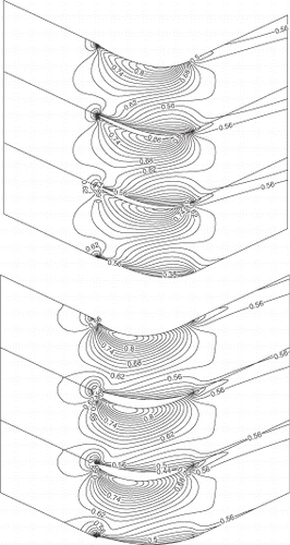
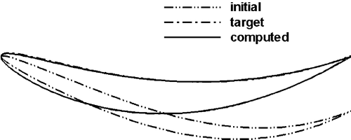
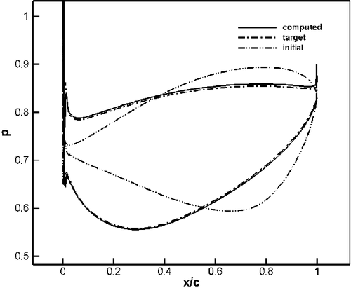
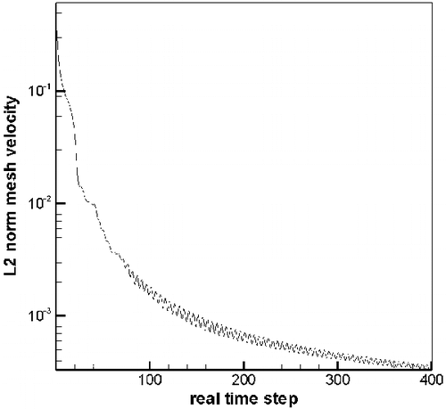
The first validation case is that of an inviscid flow in a subsonic compressor cascade. The initial and target geometries are constructed from the same family of the blade shapes, i.e. similar LE/TE profiles, inlet and exit blade angles and flow turning. The spacing to chord ratio is 0.75 and exit static to inlet total pressure ratio is 0.8 and the inlet flow angle is 25°. Although the blade shapes are from the same family, they have significantly different camber line and thickness distribution. The initial geometry corresponds to an aft-loaded blade whereas the target one corresponds to a mid-loaded blade. The maximum thickness to chord ratio is 5 and 10% for the initial and target geometry, respectively. The initial and target geometries are first analyzed by running the same code in analysis mode. shows the Mach contours resulting from the analysis of the original and target geometries. The maximum Mach numbers in the domain are 0.87 and 0.90 for the initial and target geometry, respectively. The pressure distribution of the target geometry is then used as the design input. and give a comparison of initial, target and inversely computed geometries and pressure distributions. The agreement between the target and the computed geometries is rather excellent and the target pressure distribution is also reached at convergence. The target geometry is recovered after about 400 modifications of the initial geometry. shows that the mesh velocities L2 norm has decreased three levels of magnitude during the design calculation. The computational time of the inverse design calculation is almost twice that of an analysis calculation of the same geometry with the same mesh.
This case shows the robustness of the scheme to recover a geometry corresponding to a target pressure distribution which is significantly different from that corresponding to the initial geometry. This case provides a good assessment of the design scheme for large deformation of the computational domain through the design process. It also shows that the LE/TE treatment is capable of recovering the target geometry in those regions as long as the initial and target geometries are from the same family of blade shape.
6.2. Transonic impulse turbine cascade
The second validation case is that of an inviscid flow in a transonic impulse turbine where the method usefulness in handling/controlling shocks is demonstrated. For this case, the initial and target blade shapes are similar except for the maximum thickness to chord ratio, which differs by 3%. The inlet and exit flow angles are -40.63° and 40.63° and the exit static to inlet total pressure ratio is 0.833. The initial and target geometries are first analyzed and the pressure distribution of the thinner cascade (18.5% Tmax./C) is then imposed as design input to the other geometry. Although the initial and target geometries differ by only 3% in the maximum thickness, the corresponding maximum Mach numbers are 1.5 and 1.0, respectively. shows the Mach contours of the initial and target geometries, where a shock occurs around 60% chord in the initial geometry. and show the initial, target and inversely computed pressure distribution and geometries. The technique accurately reproduces the target geometry as well as the design pressure distribution. The redesigned geometry is reached after some 200 geometry modifications. For this case, the inverse design computation time is the same as that of one analysis calculation, which can probably be attributed to the fact that the initial and target geometries differ by 3% in maximum thickness. This example shows the usefulness of the scheme to handle/control shock waves in the transonic flow regime.
6.3. Parabolic cascade
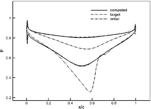
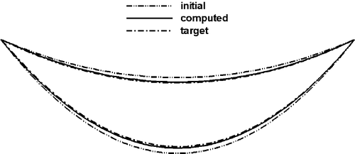
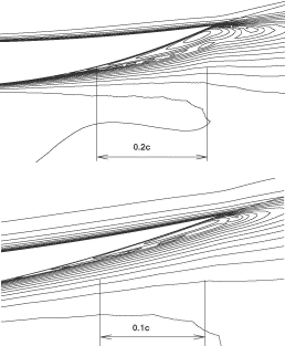
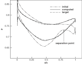
In order to validate the inverse technique for viscous flows, a parabolic cascade (of parabolic camber and thickness distributions) is chosen. The initial and target geometries have 8 and 4% maximum thickness to chord ratio, respectively. For both geometries, the spacing to chord ratio is 0.5 and the inlet and exit flow angles are 16° and -16°, and the ratio of exit static to inlet total pressure in 0.8 and the Reynolds number (Re) is 106. These two geometries are first analyzed by solving the RANS equations using the same code running in analysis mode. shows the iso-Mach contours for each configuration. The maximum Mach numbers are 0.89 and 0.85 for the initial and target geometries, respectively. shows a close-up of the Mach contours near the trailing edge of the initial and target geometries. As can be seen, the flow separates at about 80% of the axial chord on the suction side of the initial geometry, whereas for the target geometry, the flow separates at about 90% of the chord. (Note that a good design would not have such recirculation region.) The pressure distribution of the target geometry was then used as the prescribed design input for the initial geometry. shows the initial, target and computed pressure distributions on the blade surfaces and shows the initial, target and inversely computed geometries. As can be seen, the computed pressure distribution along the blade surfaces agrees fairly well with the target pressure distribution and the target blade shape has also been recovered accurately by the design method. For this inverse calculation, the L2 norm of the mesh velocities decreased by three levels of magnitude after some 250 geometry modifications. The computation time is almost twice that of an analysis calculation for this case. This case shows that the inverse method can be used for viscous flow problems at high Re typical of turbomachinery flows; it also shows that this inverse method can handle design cases with mildly separated flow regions.
6.4. Onera transonic compressor cascade
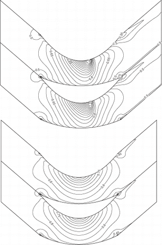
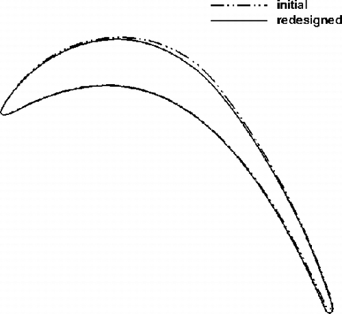
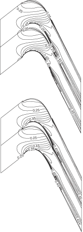
The first design case is a highly loaded transonic compressor cascade that was tested at ONERA Citation19. This compressor cascade has been redesigned using the present method to remove the passage shock. The inlet angle is 30° and the flow turning is almost 50°. The exit static pressure is 0.76 and the Re is 106. This cascade was first analyzed using RANS equations and the Mach number field, given in (top), shows the presence of a detached shock that impinges on the suction side where the maximum Mach number is around 1.34. This cascade was then redesigned to achieve a smooth target pressure distribution so as to remove the detached shock. As can be seen in (bottom), the resulting cascade is transonic shock-free with a maximum Mach number of 1.2. The redesigned geometry is obtained after some 50 geometry modifications. The computation time taken by the inverse method is less than the time taken to analyze the flow over the same geometry. This is due to the relatively small number of geometry modification, which was required to achieve the target pressure distribution. A comparison of original, target and computed pressures, given in , shows a good agreement between the target and computed pressure distributions. The results also indicate that the pressure loss of the redesigned geometry has been decreased by 21%. shows a comparison of the initial and redesign geometries.
6.5. DFVLR-T106 subsonic turbine cascade
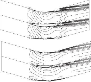
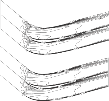
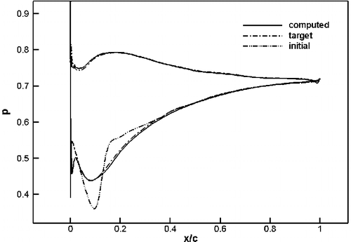
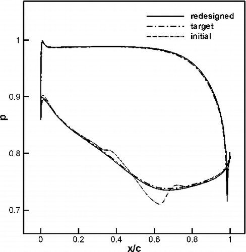
A blade cascade with a shape similar to that of the subsonic turbine cascade that was tested at DFVLR Citation19 has been redesigned to achieve a smoother target pressure distribution. The inlet flow angle is 37.7°, the exit static pressure is 0.789 and the Re is 5.105. This cascade was first analyzed assuming compressible turbulent flow. The resulting flow field shows a rapid expansion followed by high diffusion on the suction side between 40 and 65% of the chord. This cascade was then redesigned to achieve a smoother pressure distribution on the suction side, keeping the same distribution on the pressure side. shows a comparison of the initial, target and computed pressure distributions. As can be seen, the computed pressure distribution using the inverse method is in good agreement with the target pressure distribution. The Mach contour field for the initial and the redesigned geometries are shown in and , where the maximum Mach numbers are 0.664 and 0.669, respectively. The total pressure loss of the redesigned geometry has decreased by 14% compared to the original case, hence the performance of the blade has significantly improved by this design practice. The redesigned geometry is obtained after almost 120 geometry modifications, which translates to a computational time similar to an analysis calculation of the same geometry with the same mesh.
7. Conclusion
An aerodynamic inverse shape design method, applicable to two- and three-dimensional flow, has been presented, validated and applied to design linear cascades in two-dimensional viscous and inviscid compressible flow. The design variable is the pressure distribution on the blade surfaces, which has been achieved by modifying the initial guess of the geometry through an iterative process. The inverse method is implemented in a consistent manner into the unsteady RANS equations that are solved on a moving and deforming mesh using an ALE formulation. The method is first validated for inviscid and viscous flows in the subsonic and transonic flow regimes. The results of that validation indicate that the method is rather robust and capable of recovering the blade shape corresponding to the prescribed target pressure distribution. The effectiveness of the inverse method in reshaping the blades to accomplish a given pressure distribution is then demonstrated on the successful redesign of a recent transonic compressor cascade to remove the bow shock that impinges on the suction side, and a highly cambered subsonic turbine cascade to achieve a smoother pressure distribution. The validation and design cases that are presented also show the ability of the inverse method as well as the numerical scheme in handling large deformations of the computational domain, in designing transonic shock-free cascades, and in designing cascades with mild separation regions.
References
- Pierret, S, Demeulenaere, A, Gouverneur, B, Hirsch, C, and van den Braembussche, R, Designing turbomachinery blades with the function approximation concept and the Navier-Stokes equations. 2000.
- Mengistu, T, and Ghaly, W, Single and multipoint shape optimization of gas turbine blade cascades. 2004.
- Nemec, M, and Zingg, D, Towards efficient shape optimization based on Navier-Stokes equations. 2001.
- Jameson, A, Alonso, J, Reuther, J, Martinelli, L, and Vassberg, J, Aerodynamic shape optimization based on control theory. 1998.
- Leonard, O, and van den Braembussche, R, 1992. Design method for subsonic and transonic cascades with the prescribed Mach number distribution, Transaction ASME 114 (3) (1992), pp. 553–560.
- Demeulenaere, A, and van den Braembussche, R, Three dimensional inverse method for turbomachinery blading design. 1996.
- Demeulenaere, A, Leonard, O, and van den Braembussche, R, 1997. A two-dimensional Navier-Stokes inverse solver for compressor and turbine blade design, Proceedings of the I MECH E Part A Journal of Power and Energy 211 (Part A) (1997), pp. 299–307.
- De Vito, L, van den Braembussche, R, and Deconinck, H, 2003. A novel two-dimensional viscous inverse design method for turbomachinery blading, Journal of Turbomachinery 125 (2003), pp. 310–316.
- Tong, S, and Thompkins, W, 1982. Inverse or design calculation for nonpotential flows in turbomachinery cascades, Journal of Engineering for Power 106 (1982), pp. 281–285.
- Tong, S, and Thompkins, WA, Design calculation procedure for Shock-Free or strong passage shock turbomachinery cascades. 1982.
- Yang, TT, and Ntone, FWA, Viscous compressible flow direct and inverse computation with illustration. 1986.
- Ahmadi, M, and Ghaly, W, 1998. A finite volume method for inviscid transonic cascade flow with solution adaptation on unstructured mesh, CASI Journal 44 (1998), pp. 175–181.
- Jameson, A, Time Dependent calculations using multigrid, with application to unsteady flow past airfoils and wings. 1991.
- Jameson, A, Schmidt, W, and Turkel, E, Numerical solution of the euler equation by Finite-Volume methods using Runge-Kutta time stepping schemes. 1981.
- Holmes, D, and Connel, S, Solution of 2-D Navier-Stokes equations on unstructured adaptive meshes. 1989.
- Giles, M, 1990. Nonreflecting boundary conditions for euler equation calculations, AIAA Journal 28 (12) (1990).
- Baldwin, B, and Lomax, H, Thin layer approximation and algebraic model for separated turbulent flows. 1978.
- Demirdzic, I, and Peric, M, 1988. Space conservation law in finite volume calculations of fluid flow, International Journal for Numerical Methods in Fluids 8 (1988), pp. 1037–1050.
- Fottner, L, Test cases for computation of internal flows in aero engine components. 1990.
