Abstract
Inverse problems in ocean acoustics are generally solved by means of matched-field inversion in combination with meta-heuristic global search algorithms. Recently adjoint-based optimal nonlocal boundary control has been proposed as a possible complement or alternative to the traditional geoacoustic inversion methods. Especially for the assessment of a shallow water environment where field data are recorded on non-fully populated hydrophone arrays there is an inherent need for observation over a broad range of frequencies, as has been widely experimentally demonstrated. This article presents an analytic multiple frequency adjoint formulation for estimating an acoustically equivalent model of the seabed based on local impedance boundary conditions. It is intended as a benchmark solution for an extension of the approach to more sophisticated boundary conditions by means of automatic differentiation. The approach, coming from control theory, aims at inverting the impedance boundary condition along the water–sediment interface via measurements of the acoustic propagation in the water column. The impedance boundary condition thus plays the role of the control parameter of the complex pressure field in the waveguide. The developed multiple frequency adjoint method of optimal control provides an explicit representation of the gradient of the matched-field oriented cost function, and the article further proposes an analytical second-order adjoint formulation which permits the computation of the product of the Hessian matrix by a vector. By means of example inversion results the feasibility of the multi-frequency approach is discussed and the effect of a limited set of receiving locations is illustrated.
1. Introduction
Ill-posed inverse problems arise quite naturally in determining the unknown internal structure of a physical system (e.g., part of the underlying partial differential equation, its domain or its initial and/or boundary condition) from the system's behaviour, i.e., from available measurements. In the context of geoacoustic inversion Citation1–7, the problem is to recover unknown acoustic properties of the seabed from measurable ocean and acoustic field data, and probably the approach most widely used is the classical matched field technique Citation8. The goal is to minimize an objective function that compares the measured acoustic pressure field with a modeled field (replica) that is calculated for a specific parametrization of the ocean bottom. A variety of global error norms can be used as the measure of this agreement, but a convenient choice is the weighted mean-squared difference between the predicted and measured data. Regarding additional measurements, such as distinct source locations and/or different frequencies, the error functional can be augmented accordingly by summing over these additional measurement parameters. This turns out to be particularly important in order to remedy the non-convexity in the problem. In this article, we therefore consider measurements with a set of different sound frequencies. Then, the parameter set in the model space which gives the highest correlation between the replica of the field and the measured data is taken as the solution; Bartlett, matched mode, minimum variance, and multiple constraints processors are the most commonly used Citation8.
In matched field processing (MFP) the parameter estimation problem has been principally solved by means of meta-heuristic optimization techniques Citation9,Citation10, viz. genetic algorithms (GA) and simulated annealing (SA). Both of these are directed Monte Carlo searches which are based on analogies with natural optimization processes, genetic evolution and thermodynamic annealing, respectively and several modifications (differential evolution, TABU search, etc.) have been applied Citation11. These traditional global optimization methods are designed to widely search the parameter space by using a random process to iteratively update the model, and include the ability to move uphill in the objective function to escape from local minima. As a consequence, these methods require a huge number of function calls and are relatively inefficient at moving downhill, particularly near convergence and for problems involving correlated parameters.
The approach presented here extends the concept of optimal control applied earlier by Asch et al. in Citation12,Citation13 to multiple frequencies. This extension, based on local boundary conditions, is proposed as a first step towards the use of adjoint methods for solving inverse problems in shallow water acoustics. Initially, the need for observation over a wide range of frequencies has been experimentally first demonstrated by Hermand et al. in Citation14 and subsequently expanded in Citation15. The first conventional MFP was extended to match the spatial structure of continuous-wave (CW) acoustic pressure fields with joint optimization across discrete frequencies, while in the latter a model-based, time-reversal processing was developed to exploit waveguide modal dispersion and therefore the phase relationship between a broad continuum of frequencies. In a related form this concept was recently applied by Le Gac et al. in Citation16.
In this article we take up this argument and treat the boundary control problem by means of an analytic multiple-frequency adjoint model which is derived for parabolic-type approximations. Adjoint based optimal control of nonlocal boundary conditions at a single frequency has recently been introduced in Citation17, however, due to the spectral integral representation of the nonlocal boundary condition the control approach therein is not easily extendable analytically to multiple frequencies. In this article, we derive an analytic multi-frequency adjoint model using a locally reacting impedance boundary condition according to Robertson et al. Citation18 at the water–sediment interface. The obtained formulae serve as benchmark solutions for the extension of the approach to more sophisticated boundary conditions representing, e.g., a layered elastic bottom or bottom types with linear depth dependence of the refraction index and shear, by means of automatic differentiation.
The presented analytic approach can be considered complementary to the discrete adjoint method proposed, e.g., in Citation19 for ocean acoustic tomography. Like Citation19, many works particularly in the geophysical literature first discretize the underlying problem, and subsequently apply manipulations to the finite difference matrices, rather than to the governing differential or integral equations.
The adjoint method of optimal control Citation20,Citation21 is a technique used for calculating an exact expression of the gradient of a cost function that depends implicitly on the control variables with respect to which one has to differentiate. The method avoids the costly calculation of the derivative of the implicit function, and is thus extremely well suited to optimal control problems. Adjoint-based methods are especially attractive for problems where it is not possible to use a low-dimensional parameterization in combination with classical meta-heuristic approaches. The high potential of adjoint-based methods has been demonstrated, e.g., in fluid dynamics Citation22, inverse scattering Citation23, optimal design Citation24, seismic inversion Citation25 or meteorology Citation26. Related problems of exact and approximate boundary controllability are addressed in Citation27–29 for the heat equation and systems associated to a Laplace operator on a regular bounded domain, in general.
Recently, the so-called second-order adjoint techniques have been introduced for the analysis of ill-posed problems, e.g., in computational fluid dynamics Citation30, Citation31 or for data assimilation in meteorology Citation32. Second-order derivative information is essential for the computation of the sensitivity with respect to the model inputs, especially the observations, or for the evaluation of statistical quantities such as correlation matrices. For this purpose, the major automatic differentiation tools had the option for Hessian calculation recently implemented into their code.
Following a detailed description of the direct problem and the associated inverse formulation in sections 2 and 3 respectively, we present a formal description of the adjoint state method in section 4. In section 5 this method is applied to the inverse problem introduced in section 3, in order to derive the adjoint of the forward model and obtain both the first and second-order analytical gradient information. By means of example inversion results the feasibility of the multi-frequency approach is discussed and the effect of a limited set of receiver locations is illustrated. Section 6 concludes with some remarks about the possible extensions of this approach in ocean acoustics.
2. The direct problem
Starting from the homogeneous wave equation for the pressure in ideal fluids
(------140785--1)
and considering a stratified environment of a water layer of constant density ρw and depth zb and with sound speed profile c(r) overlying a locally reacting boundary, the Fourier-transformed Helmholtz equation is obtained as
(------140785--2)
Here p=p(r) is the acoustic pressure, k is the medium wave number with
k0 is a reference wavenumber, c0 is a reference velocity, n is the index of refraction and ω =2 π f with f the sound frequency. The environment as it is described is axially symmetric and the Helmholtz equation in cylindrical coordinates can be written as
(------140785--3)
By using the parabolic decomposition technique, the acoustic pressure p is expressed in terms of the zeroth-order Hankel function
(------140785--4)
The parabolic equation for u, the envelope of the acoustic pressure field, after making the standard assumptions and approximations Citation33 is
(------140785--5)
By introducing a harmonic point source located at depth zs in the water column as well as suitable boundary conditions for the sea surface and the sea floor, we obtain the non-homogeneous Helmholtz equation describing acoustic propagation in the medium.
In order to obtain a well-posed initial boundary value problem, we suppose that the boundary condition at the sea surface is a Dirichlet condition (perfectly reflecting interface), whereas the boundary condition on the sea floor zb = H is given by
(------140785--6)
where γ is a range-dependent, complex-valued function which represents a locally reacting boundary. As a synthesis the continuous problem can be written:
(------140785--7)
(------140785--8)
(------140785--9)
(------140785--10)
where S(z,zs), the initial pressure field, is given by a classical Gaussian starter as proposed by Tappert Citation33. The boundary value problem can then be solved for 0 ≤ r ≤ R a maximum range, and 0 ≤ z ≤ H.
3. The inverse problem
In the following, we consider the case of a point source and a distant vertical receiver array (VRA) in a waveguide. Given a set of acoustic data which sufficiently represents the spatial structure of the complex pressure field measured along the VRA at a given range for a number of different frequencies, the inverse problem is to recover the unknown boundary coefficient γ(r) that plays the role of a control function.
Suppose j represents an index that identifies a particular acoustic experiment, where j=1, …, m. For example, j could identify a distinct source or receiver location or, as in the following, a different source frequency (in which case we also change k to kj). Let us suppose that we measure on a VRA situated at the range r = R for m different source frequencies and define the cost function
(------140785--11)
where uj(γ ; r, z) is obtained from solving the direct problem in equations (7–10) with the source frequency fj. As stated in equation (11), we must add regularization terms on γ in order to make the optimization problem less ill-posed by restoring the continuous dependence (see e.g. Citation34–37). In addition, the use of multi-tone signals in a multiple frequency optimization constrains the admissible space of solutions and thus helps to mitigate non-uniqueness problems by restoring the convexity. Properties of local convexity can further be deduced by studying the Hessian of the cost function in the vicinity of the optimum to ensure a unique solution Citation32.
The inverse problem can then be stated as follows: for given measurements uobs, j(R, z) of an acoustic field, find the complex coefficient γ(r) of the impedance boundary condition that minimizes the cost function J(γ). In other words, find , the optimal control, such that
(------140785--12)
where
is the set of admissible controls.
4. The adjoint state method
Before discussing the method itself, we introduce some general definitions and notation for inverse problems. A more detailed review of the approach can be found in Citation34 where the important issue of regularization is also discussed (see also Citation37 for an application to the geoacoustic inversion problem). In Citation38, one can find a discussion of the adjoint approach and of the Fréchet derivatives that we use to derive our functional gradient.
For an abstract formulation of the inverse problem under consideration, we introduce three Hilbert spaces, the model (control or parameter) space G, the state space U, and the data (or observation) space D. The state space U allows an explicit description of the dependence between the control (parameters) and the data. In the remaining section, the state u in this notation shall formally represent the envelope of the two-dimensional complex pressure field at selected source frequencies, different experiment geometries etc. Nonetheless, the existence of the state does not dispense us of introducing the observation, since the state is in general, not measurable. Two mappings (equations) give the relationships between these three spaces. The state equations (7–10) which link implicitly the control and the state is formally written as
(------140785--13)
where Z is another Hilbert space. We suppose that there exists a subspace
(the space of “admissible” controls) such that for all
, F locally defines a unique state u = uγ. It will be useful to denote the solution of the state equation (13) as
(------140785--14)
Furthermore, a second equation, the so-called observation equation, extracts from the state the part that corresponds to the measurements. This will often be an injection due to the inherent difficulty of measuring the state at all points, and is introduced here as
(------140785--15)
In the underlying physical problem, H may represent the mapping of u, the envelope of the acoustic pressure field back to acoustic pressure p according to equation (4) and take into account the actual hydrophone spacing on the antenna array. Here, we have made the simplifying assumption that the observation is a linear operator, independent of the control. The extension to a more general situation is not difficult. If we substitute the solution of equation (13) into equation (15), we obtain the mapping that relates the control (or the parameter) to the observation. We write
(------140785--16)
The inverse problem is then: given an observation dobs, solve the equation
(------140785--17)
for the control (or parameter) γ. In most cases, the mapping Φ is defined implicitly. It is also nonlinear, even if the state and observation equations are linear. This clearly makes it difficult to solve the inverse problem. The problems in equation (16) or (17) may not have a solution, and even if they have one, the inverse mapping is not necessarily continuous. We are thus led to introduce a weaker formulation, the so-called output least-squares method for the cost function J, which has turned out to be very effective. We formally rewrite equation (11) to obtain the following minimization problem:
(------140785--18)
The observation is given once and for all, then to evaluate the functional J at a parameter γ, we start by solving the state equation (13), followed by the observation equation (15), and finally we compare the simulated observation to the measured one. This reformulation does not transform an ill-posed problem into a well-posed one. However, it re-establishes the existence. Indeed, even if no solution exists for the equation (16), the minimization problem will necessarily have a solution since the cost function J is positive. On the other hand, nothing guarantees that the minimum will be attained at a point
. Another important question is that of uniqueness which is related to the convexity of J and once more, there are no guarantees. The formulation (18) does of course have numerous qualities:
| • | It gives a systematic method for the formulation of inverse and optimal control problems. | ||||
| • | In certain cases we can prove the necessary properties of J for the existence of a minimum. | ||||
| • | It enables us to regularize the problem by means of a family of well-posed problems whose limit solution converges to the solution of the original problem. | ||||
| • | There are robust, well-studied numerical methods for solving optimization problems. | ||||
| • | Under reasonable hypotheses on the data, the functional J is differentiable and can thus be minimized by local gradient-based optimization methods. | ||||
The difficulties arise from a combination of factors.
| • | The cost function is in general non-convex. This leads to the existence of local minima and gradient-based optimization algorithms which experience difficulties to converge to the global minimum. An initial guess, too far from the correct solution, can result in the inversion process getting caught in a local minimum, i.e., in a suboptimal solution of the underlying physical problem. | ||||
| • | The inverse problem can be under-determined due to a lack of data. Here, once again, we can have several solutions producing the same observations. | ||||
| • | The lack of continuity produces a discontinuity. Noise in the data can prevent us from being able to solve the problem. This can be (partially) dealt with by penalization techniques. | ||||
4.1. Lagrange multiplier method
In the following, the adjoint field will be interpreted as a continuous Lagrange multiplier function λ. We wish to minimize the error functional J(γ) in equation (18) subject to the constraint that u obeys the state equation (13). We thus consider equation (13) as a side condition and claim that the variables γ and u vary independently. The Lagrangian in this case is constructed (at least formally, since we do not have a finite number of constraints):
(------140785--19)
where ⟨·, ·⟩ denotes an appropriate scalar product defined on Z. Now, if u satisfies the state equation corresponding to the parameter γ, then we have the identity
(------140785--20)
Differentiating this relation, we obtain
(------140785--21)
The difficult part is then to calculate ∂ γ u(γ). If we can choose λ ∈Z such that this last term disappears, we will have a simple expression for the derivative of J. To this end, we suppose that δ u = ∂ γ u(γ) δ γ is an independent quantity, and we require that the operator δ u → ∂ u
disappears. We thus define the abstract equation
(------140785--22)
and by expanding the expression for
(------140785--23)
we obtain
(------140785--24)
Now, if we identify the Lagrange multiplier λ as the adjoint state
, which satisfies the corresponding adjoint equation (24), the desired functional gradient is directly calculated from the differential of J
(------140785--25)
and we observe that in fact we obtain the gradient of J,
(------140785--26)
We summarize all of this in a theorem. See Citation34 for the proof in a general setting.
THEOREM 4.1
If v is the solution of the adjoint equation (24), then the gradient of J at the point γ is given by equation (26), where u = u(γ) is the solution of the state equation (13) corresponding to γ.
Remark 4.2
In practice, the most useful form of the adjoint equation is the “variational” formulation in equation (23). In fact, it is not always convenient to calculate the adjoint operators. By contrast, it is always simple (we shall see subsequently) to start out from equation (23), and to manipulate it (by integration or summation by parts), in order to reach an explicit adjoint equation. In the same way, it is often more convenient to start out from equation (25) and to manipulate it in order to identify the gradient than to use the formula in equation (26) as is.
We resume the main steps of the adjoint method in the following theorem.
THEOREM 4.3
The computation of the gradient of the functional in equation (18) is achieved by the following steps:
| • | Define the Lagrangian by equation (19). | ||||
| • | Solve the (variational) adjoint equation (23) that determines the adjoint state v. | ||||
| • | The differential of J is given by equation (25) and it enables the identification of the gradient of J. | ||||
5. An iterative inversion algorithm for multiple frequencies
Returning to the multiple frequency formulation of the cost function in equation (11) in section 3, the main objective is to compute the functional gradient ∇J of the error functional J. We start by taking the Gâteaux (directional) derivative of the cost function J in equation (11)
(------140785--27)
(------140785--28)
(------140785--29)
(------140785--30)
where
is a variational variable, ϕ a smooth perturbation of the control γ with compact support and g is the function defined by
(------140785--31)
We introduce the real-valued scalar product with
(------140785--32)
where
is the complex conjugate of z2. The scalar product satisfies:
(------140785--33)
(------140785--34)
(------140785--35)
(------140785--36)
and the derivative formula:
(------140785--37)
We then have
(------140785--38)
where each wj=duj/dt satisfies the tangent linear model obtained from the direct problem in equations (7–10)
(------140785--39)
(------140785--40)
(------140785--41)
(------140785--42)
The functional derivative of J is then with t = 0,
(------140785--43)
Now, if we further require that the adjoint state vj for each additional measurement parameter obey the following adjoint equation
(------140785--44)
(------140785--45)
(------140785--46)
(------140785--47)
we can calculate the scalar product of the adjoint state and the tangent linear model according to equation (23) in order to finally identify the desired gradient of the cost function.
Note that the adjoint problem contains a “terminal” condition (45) at r = R and is thus backward in r. Note also that the boundary condition (47) is still dissipative in spite of the change of sign of γ.
Then, integrating by parts yields
Thus,
and
(------140785--48)
According to equation (43) this is equivalent to
(------140785--49)
which in turn can be rewritten as:
(------140785--50)
The gradient ∇J thus obtained is in fact fully consistent with the result stated in equation (26).
5.1. The gradient method
Once the gradient in equation (50) is computed, iterative descent algorithms can be applied to drive the cost function towards a minimum. Steepest descent is the simplest method to locate a local minimum of J(γ) by updating
(------140785--51)
for n=0, 1, … until convergence. In order to accelerate the convergence we use a conjugate gradient method of Fletcher–Reeves or Polak–Ribière type as proposed in Citation39. Here, the update is given by
(------140785--52)
where αn is the step length that minimizes J in the direction dn, and this direction is computed in two steps:
(------140785--53)
(------140785--54)
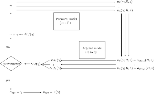
displays in the form of a flow diagram the principle of a multiple frequency adjoint optimization approach.
Starting with an initial guess γ init the direct model is run in parallel for the different measurement parameters, here a set of m frequencies, and the resulting mismatches between model results and observations are used to initiate the adjoint model runs. With the information thus obtained, the overall multi-frequency-based gradient ∇J of the cost function in equation (11) is determined as described in equation (50) and the current γ updated accordingly to start the next iteration until the stopping criteria are met.
5.2. Second-order adjoint
Since the adjoint method provides a very efficient way for carrying out the gradient calculation, it is quite natural to extend this approach for Hessian calculation. A straightforward way to obtain Hessian information is to proceed via direct numerical differentiation of the gradient obtained from the first-order adjoint problem (AD)
(------140785--55)
where a is the differentiation parameter. However, if the parameter a is poorly chosen, a low Hessian accuracy may result due to computing the difference between two small values. A more elegant approach to Hessian action calculation is based on the second-order adjoint problem (TLAD) Citation31. For this purpose, we calculate the tangent linear adjoint model and denote it in the following as the second-order adjoint model. To this end, we require that the tangent linear adjoint field ξ j=dvj/dt satisfies the second-order adjoint equation obtained from the adjoint problem in equations (44–47)
(------140785--56)
(------140785--57)
(------140785--58)
(------140785--59)
A common interpretation in the context of the adjoint problem is that the observed field is a superposition of a baseline field due to the presumed medium and a perturbed field due to the unknown medium perturbations which one inverts for Citation19. Keeping in mind that for a given perturbation Δγ, the perturbations Δ uj and Δ vj are provided by the tangent linear fields wj and the second-order adjoint field ξj respectively, one can thus write
(------140785--60)
(------140785--61)
For the gradient ∇J, one obtains in analogy
(------140785--62)
Inserting for the gradient from equation (50)
(------140785--63)
gives
(------140785--64)
(------140785--65)
from which the product of the Hessian matrix by the vector Δγ can be identified as
(------140785--66)
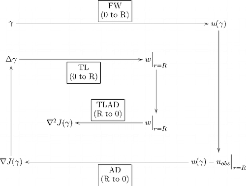
In order to obtain the product ∇ 2 J (γ) Δ γ, it is necessary to sequentially solve:
| i. | Forward problem (FW), equations (7–10) from r = 0 to r = R. | ||||
| ii. | First-order adjoint problem (AD), equations (44–47) from r = R to r = 0. | ||||
| iii. | Tangent linear problem (TL), equations (39–42) from r = 0 to r = R. | ||||
| iv. | Second-order adjoint problem (TLAD), equations (56–59) from r = R to r = 0. | ||||
Using the values of all four fields along the bottom interface, i.e., the direct and the adjoint field as well as their tangent linear counterparts, the product ∇ 2 J (γ) Δ γ can be computed according to equation (66). The Hessian/vector product is required, e.g., in truncated Newton-type large-scale optimization methods. displays the conceptual flow of the second-order adjoint scheme – for convenience just the single-frequency (m = 1) case is shown.
5.3. Numerical simulations
In the following example, to illustrate the adjoint-based inversion, both the direct and adjoint problem are solved by means of an implicit finite difference (FD) scheme of Crank–Nicholson type. The local impedance boundary condition in equation (10) is included as an ordinary differential equation in z. A straightforward conjugate gradient optimization scheme (section 5.1) is used as an iterative descent algorithm to drive the cost function to a minimum.
As a test case we use a range-independent, shallow-water waveguide with a standard isospeed water column of 1500 m s−1 and a water depth of 135 m with the local impedance boundary condition a given real-valued sinusoidal function. Note that according to the gradient of the cost function in equation (50) we cannot expect any bottom impedance to be retrieved in the non-insonified region situated directly below and in close vicinity to the source, which in the current example is located at a depth of 93 m. This is why our initial guess (dashed, red line in the figures) is taken to be the true γ over the first 150 m. In the following we first consider the single-frequency (m = 1) adjoint inversion results obtained for a complex γ at f = 500 Hz as a reference case. shows the initial acoustic field, the true field and the field obtained after inversion.
Figure 3. The initial (a), true (b) and calculated (c) envelope u(r, z) of the acoustic pressure field obtained for a frequency of f=500 Hz.
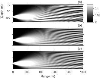
Already for the single-frequency case, the inversion results in reveal that the inversion succeeds in reconstructing both the field at maximum range as well as the principal features of the field over the entire range.
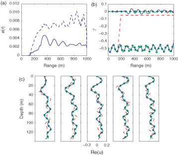
Figure 4. Single-frequency inversion results obtained with f=500 Hz for the case of a complex γ. Integrated relative error e(r) at the beginning (dashed, red) and at the end of the inversion (solid, blue) (a), the inversion of γ with the initial (dashed, red), true (dots, green) and the inverted (solid, blue) for the real part (lower curves) and the imaginary part (upper curves) respectively (b). The real and imaginary part of the inverted (solid, blue), initial (dashed, red) and true (dots, green) acoustic field at range R=1000 m are plotted in (c) and (d). There is a nearly perfect match between the inverted and true acoustic field.
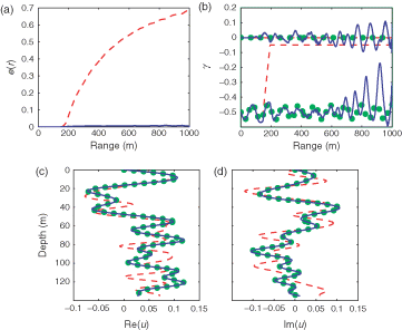
The integrated relative error
(------140785--67)
is a few percent only. Note the manifestation of non-uniqueness for the single-frequency case (f = 500 Hz) in , where the inverted γ is quite different from its true value. Destructive interference of the acoustic field at ranges >700 m leads to isolated shadow zones along the ocean–bottom interface. Since the acoustic field u in these regions is close to zero, the value of the the complex coefficient γ(r) of the impedance boundary condition is ill-determined at the range intervals that correspond to these shadow zones ().
By means of extension of the adjoint optimization formalism to multiple frequencies, the performance of the inversion process can be considerably enhanced because the interference pattern is a frequency-dependent characteristic. The inversion results for m = 5 source frequencies f={400, 425,450,475,500 Hz} are displayed in .
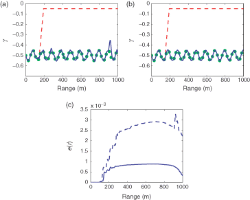
Figure 5. Multiple frequency inversion results obtained with f={400,425,450,475,500 Hz} for the case of a complex γ. Integrated relative error e(r) (solid, blue) (for comparison the relative error obtained in figure 4 for a single frequency is repeated as the dashed, blue curve) (a) and the inversion of γ (b). The real part of the inverted (solid, blue), initial (dashed, red) and true (dots, green) acoustic fields are plotted in (c) for the different frequencies. Again there is a nearly perfect match between the inverted and true acoustic field.
shows the corresponding inversion results for the case of an a priori real γ. Upon completion of the multi-frequency inversion the retrieved γ is almost identical to the true one.
Figure 6. Comparison of single and multiple frequency inversion results for the case of a real γ. The inversion of γ for the single frequency (a) and the multi-frequency (b) inversion. Integrated relative error e(r) for the single frequency (dashed, blue) and multi-frequency (solid, blue) inversion (c).
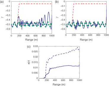
As a further example, we illustrate the use of the multiple-frequency adjoint inversion for the case of a physical array with a discrete set of receivers. In contrast to the previous cases where the adjoint starter uj-uobs, j in equation (45) could be determined over the full depth of the FD grid, in realistic applications the data, uobs, j is available only on a limited set of receiving locations and the cost function in equation (11) has to be modified accordingly to restrict the sum exclusively to the discrete set of receiver positions. In order to address the problem of backpropagating the model–data mismatch we adapt the so-called acoustic retrogation processor Citation40,Citation41 for application within the adjoint approach.
As an example we choose 16 equidistantly spaced receiver depths spanning the water column between 4 and 131 m. With respect to the previous examples the vertical spacings between adjacent observation points are increased by a factor of 32. As can be seen in the decrease in observability due to the reduction of observation points in the single frequency result can be compensated by means of the multiple frequency extension; m = 5 source frequencies f={400, 425,450,475,500 Hz} were taken for this test. Note that all results shown in this article are non-regularized.
Figure 7. Comparison of single and multiple frequency inversion results for the case of a real γ and a realistic receiver array with 16 elements. The inversion of γ for the single frequency (a) and the multi-frequency (b) inversion. Integrated relative error e(r) for the single frequency (dashed, blue) and multi-frequency (solid, blue) inversion (c).
6. Conclusion
In this article, we have developed an analytic multiple frequency variational approach based on the optimal control of the standard PE approximation using a local impedance boundary condition. Assuming that the bottom can be represented by an acoustically equivalent impedance, we observed that the developed approach is a good proof of concept; especially the use of a multiple frequency-based cost function has been shown to further constrain the admissible space of solutions and therefore to mitigate the common problem of non-uniqueness. The numerical implementation of this method is robust (provided that we supply initial guesses that are sufficiently close to the desired γ) and accurate, and converges in a small number of iterations (5 to 10).
It is the main intention of the article to present the analytic results that constitute the fundamental mathematical framework of an alternative solution approach for geoacoustic inversion. The exact analytic treatment of the problem legitimates the use of the standard parabolic approximation in combination with a locally reacting sea bottom boundary condition.
From a practical point of view, the geoacoustic characterization of a shallow water environment clearly requires a higher degree of complexity in the propagation model and boundary conditions with an explicit handling of the geoacoustic parameters. This does not allow for an analytic treatment anymore, but instead requires numerical adjoint generation.
The corresponding extension of the presented analytical approach to a higher-order parabolic approximation, the implementation of more complex nonlocal boundary conditions and the direct inversion for the underlying geoacoustic parameters are in fact the subject of currently ongoing research. Especially by means of automatic adjoint derivation, state-of-the-art propagation tools and more sophisticated layered bottom models can be included in the inversion process. At sea experiments that follow-up the previous work by Hermand et al. Citation14,Citation15 and Le Gac et al. Citation16 are planned for 2006 and shall be used to validate the method.
Further investigations may be pursued also in the frame of aerial acoustics Citation42,Citation43 where the local impedance boundary conditions have been shown to be reasonably accurate Citation18 for ground surface modeling.
Acknowledgments
The research is funded by the Royal Netherlands Navy and the Service Hydrographique et Océanographique de la Marine Française under the REA and SIGMAA projects (Contract Nos. 631.380026.01 and CA-2004/03/CMO) in the framework of the Joint Research Project AO-BUOY at the NATO Undersea Research Centre. The study contributes to the AquaTerra Project “Integrated modeling of the river-sediment-soil-groundwater system” funded by the European 6th Framework Programme, Research Priority 1.1.6.3 Global Change and Ecosystems (European Commission, Contract No. 505428-GOCE). It is a part of Flux3 “Input/output mass balances in river basin: dissolved and solid matter load”, a subcomponent of the AquaTerra Integrated Project.
References
- Diachok, O, Caiti, A, Gerstoft, P, and Schmidt, H, 1995. Full Field Inversion Methods in Ocean and Seismo Acoustics. Norwell, MA, USA, and Dordrecht, The Netherlands: Kluwer Academic Publisher; 1995, (Eds.).
- Wilson, JH, Rajan, SD, and Null, JM, 1996. Inverse techniques and the variability of sound propagation in shallow water, IEEE Journal of Oceanic Engineering, Special issue 21 (4) (1996), (Eds.).
- Caiti, A, Hermand, J-P, Porter, MB, and Jesus, S, 2000. Experimental Acoustic Inversion Methods for Exploration of the Shallow Water Environment. Dordrecht: Kluwer Academic; 2000, (Eds.).
- Taroudakis, MI, and Markaki, MG, 2001. Inverse Problems in Underwater Acoustics. New York: Springer; 2001.
- Chapman, R, Chin-Bin, S, King, D, and Evans, R, 2003. Geoacoustic inversion in range-dependent shallow water environments, IEEE Journal of Oceanic Engineering, Special issue (Pt.1) 28 (3) (2003), (Eds).
- Chapman, R, Chin-Bin, S, King, D, and Evans, R, 2004. Geoacoustic inversion in range-dependent shallow water environments, IEEE Journal of Oceanic Engineering, Special issue (Pt.2) 29 (1) (2004), (Eds).
- Caiti, A, Chapman, R, Hermand, JP, and Jesus, S, 2004. Acoustic Inversion Methods and Experiments for Assessment of the Shallow Water Environment. Dordrecht: Springer; 2004, (Eds), (in print).
- Tolstoy, A, 1993. Matched Field Processing for Underwater Acoustics. Singapore: World Scientific; 1993.
- Sen, MK, and Stoffa, PL, 1995. Global Optimization Methods in Geophysical Inversion. The Netherlands: Elsevier Publishing Co.; 1995.
- Spall, JC, 2003. Introduction to Stochastic Search and Optimization: Estimation, Simulation and Control. New York: Wiley Publishers; 2003.
- Voss, S, Martello, S, Osman, IH, and Roucairol, C, 1998. Meta-heuristics: Advances and Trends in Local Search Paradigms for Optimization. Berlin: Springer; 1998.
- Asch, M, Le Gac, J-C, and Helluy, P, An adjoint method for geoacoustic inversions. Presented at Proceedings of the 2nd Conference on Inverse Problems, Control and Shape Optimization. 2002.
- Le Gac, J-C, Stéphan, Y, Asch, M, Helluy, P, and Hermand, J-P, 2004. "A variational approach for geoacoustic inversion using adjoint modeling of a PE approximation model with non local impedance boundary conditions". In: Tolstoy, A, Teng, YC, and Shang, EC, eds. Theoretical and Computational Acoustics 2003. Singapore: World Scientific Publishing; 2004. pp. 254–263.
- Hermand, J-P, and Gerstoft, P, 1996. Inversion of broad-band multitone acoustic data from the YELLOW SHARK summer experiments, IEEE Journal of Oceanic Engineering 21 (4) (1996), pp. 324–346.
- Hermand, J-P, 1999. Broad-band geoacoustic inversion in shallow water from waveguide impulse response measurements on a single hydrophone: theory and experimental results, IEEE Journal of Oceanic Engineering 24 (1) (1999), pp. 41–66.
- Le Gac, J-C, Asch, M, Stéphan, Y, and Demoulin, X, 2003. Geoacoustic inversion of broadband acoustic data in shallow water on a single hydrophone, IEEE Journal of Oceanic Engineering (2003).
- Meyer, M, and Hermand, J-P, 2005. Optimal nonlocal boundary control of the wide-angle parabolic equation for inversion of a waveguide acoustic field, Journal of the Acoustical Society of America 117 (5) (2005), pp. 2937–2948.
- Robertson, JS, Siegmann, WL, and Jacobson, MJ, 1995. Low-frequency sound propagation modelling over a locally reacting boundary with the parabolic approximation, Journal of the Acoustical Society of America 98 (2) (1995), pp. 1130–1137.
- Hursky, P, Porter, MB, Hodgkiss, WS, and Kuperman, WA, 2004. Adjoint modeling for acoustic inversion, Journal of the Acoustical Society of America 115 (2) (2004), pp. 607–619.
- Lions, JL, 1971. Optimal Control of Systems Governed by Partial Differential Equations, volume 170 of A Series of Comprehensive Studies in Mathematics. New York: Springer Verlag; 1971.
- Lions, JL, 1988. Exact controllability, stabilization and pertubations for distributed systems, SIAM Review 30 (1988), pp. 71–86.
- Leredde, Y, Lellouche, J-M, Devenon, J-L, and Dekeyser, I, 1998. On initial, boundary conditions and viscosity coefficient control for Burgers' equation, International Journal for Numerical Methods in Fluids 28 (1998), pp. 113–128.
- Colton, D, and Kress, R, 1998. Inverse Acoustic and Electromagnetic Scattering Theory, volume 93 of Applied Mathematical Sciences. Berlin: Springer; 1998.
- Giles, MB, and Pierce, NA, 2001. Analytic adjoint solutions for the quasi 1d euler equations, Journal of Fluid Mechanics 426 (2001), pp. 327–345.
- Tarantola, A, 1984. Inversion of seismic reflection data in the acoustic approximation, Geophysics 49 (1984), pp. 1259–1266.
- Talagrand, O, and Courtier, P, 1986. Les équations adjointes – Application à la modélisation numérique. Atelier modélisation de l'atmosphère, Direction de la météorologie. France: Toulouse; 1986.
- Carthel, C, Glowinski, R, and Lions, JL, 1994. On exact and approximate boundary controllabilities for the heat equation: a numerical approach, Journal of Optimization Theory and Aplications 82 (3) (1994), pp. 429–484.
- Akkouchi, M, and Bounabat, A, 2001. Optimality conditions and adjoint state for a perturbed boundary optimal control system, Applied Mathematics Letters 14 (7) (2001), pp. 907–912.
- Akkouchi, M, and Bounabat, A, 2001. Some boundary optimal control problems related to a singular cost functional, Annales Mathématiques Blaise Pascal 8 (1) (2001), pp. 7–15.
- Alekseev, AK, and Navon, IM, 2001. The analysis of an ill-posed problem using multi-scale resolution and second-order adjoint techniques, Computer Methods in Applied Mechanics and Engineering 190 (2001), pp. 1937–1953.
- Alekseev, AK, and Navon, MI, 2002. On estimation of temperature uncertainty using the second-order adjoint problem, International Journal of Computational Fluid Dynamics 16 (2) (2002), pp. 113–117.
- Le Dimet, FX, Navon, IM, and Daescu, DN, 2002. Second-order information in data assimilation, Monthly Weather Review 130 (3) (2002), pp. 629–648.
- Jensen, FB, Kuperman, WA, Porter, MB, and Schmidt, H, 1994. Computational Ocean Acoustics. New York: American Institute of Physics Press; 1994.
- Kravaris, C, and Seinfeld, JH, 1985. Identification of parameters in distributed parameter systems by regularization, SIAM Journal of Control and Optimization 23 (1985), pp. 217–241.
- Engl, HW, Hanke, M, and Neubauer, A, 1999. Regularization of Inverse Problems. Dordrecht: Kluwer Academic Publishers; 1999.
- Zhdanov, MS, 2002. Geophysical Inverse Theory and Regularization Problems Number 36 in Methods in Geochemistry and Geophysics. Amsterdam: Elsevier; 2002.
- Meyer, M, Hermand, J-P, Le Gac, J-C, and Asch, M, Penalization method for WAPE adjoint-based inversion of an acoustic field. Presented at Proceedings of the 7th European Conference on Underwater Acoustics, ECUA 2004. July, 2004.
- Norton, SJ, 1999. Iterative inverse scattering algorithms: Methods of computing Fréchet derivatives, Journal of the Acoustical Society of America 106 (5) (1999), pp. 2653–2660.
- Frandsen, PE, Jonasson, K, Nielsen, HB, and Tingleff, O, 1999. "Unconstrained optimization". Technical University of Denmark; 1999, Lecture note IMM-LEC-2.
- Tappert, FD, Nghiem-Phu, L, and Daubin, SC, 1985. Source localization using the PE method, Journal of the Acoustical Society of America 78 (S1) (1985), p. S30.
- Thomson, DJ, Ebbeson, GR, and Maranda, BH, A matched field backpropagation algorithm for source localization. Presented at Proceedings of MTS/IEEE Oceans 1997. 1997.
- Gilbert, KE, and White, MJ, 1989. Application of the parabolic equation to sound propagation in a refracting atmosphere, Journal of the Acoustical Society of America 85 (2) (1989), pp. 630–637.
- West, M, Gilbert, KE, and Sack, RA, 1992. A tutorial on the parabolic equation (PE) model used for long range sound propagation in the atmosphere, Applied Acoustics 37 (1992), pp. 31–49.
