Abstract
In this article, a neural network procedure is suggested to inversely determine the variable binder force in U-shaped forming from the deforming shape of the part. The finite element method (FEM) is used to simulate the forming process. The inputs of the neural network (NN) model come from the deformation shape of the part. The outputs of the NN are the stepped variable binder force parameters. To reach the desired deformation, the NN model will go through a progressive retraining process. A constant binder force simulation method is also recommended to obtain the desired deformation shape. The numerical result for model NUMISHEET’93 demonstrates the efficiency of the present procedure.
1. Introduction
The accuracy of the products has become the key issue of the manufacturing process. High accuracy in part dimension can improve the performance, decrease the cost of the products, and obtain profits for the company. In sheet metal forming, the major fault is the springback of the material. The uneven distribution of stress along the sheet thickness direction relaxes during unloading, thus producing the springback Citation1. Springback is a very complex mechanical phenomenon that involves the material property and the processing parameters such as friction coefficient, thickness of the metal plate and temperature, etc. In recent years, many works have been reported for the investigation of the springback Citation1–9.
In sheet metal forming, the binder force is helpful to reduce the springback. However, the bigger binder force causes a subsequent increase of the maximum strain in the material Citation1, and often splits the material. To obtain both small springback and strain, Ayres Citation2, Hishida and Wagoner Citation3, Sunseri et al. Citation4 proposed the stepped variable binder force trajectory. Investigating some typical component geometries of a ‘hat-shaped section’ by a model test, Schmockel and Beth Citation5 found that a sudden increase of the binder force at the end of the forming process is particularly beneficial to retain part shape. These methods divide the forming process into two separate parts. In the first part, a low binder force (LBF) acts on the sheet metal, while in the second part the LBF is replaced by a high binder force (HBF). In this way, the springback and the maximum strain can both become smaller than those under the constant binder force (CBF). Their work points out a proper way for controlling the springback, however, how to determine the variable binder force is not considered.
Due to its strong function in information processing, neural network (NN) has been introduced into sheet metal forming to establish the relations among concerning variables. Cho et al. Citation6 adopted an NN to predict the force in cold rolling. Di and Thomson Citation7 used NN to predict the wrinkling limit in square metal sheets under diagonal tension. Cao et al. Citation1 obtained the input parameters of the NN from punch force curve and considered the influences of plate thickness and friction coefficient systematically. These methods obtained the training samples for NN through punch force trajectory, while achieving the punch force curve was not an easy process.
In this paper, the springback is controlled via a stepped variable binder force and an efficient procedure is suggested to inversely determine the variable binder force parameters in U-shaped part forming. The present method avoids directly analyzing the springback and intends to establish the connections between the final deforming shape of the part and the stepped variable binder force parameters. In the computation example, the results demonstrate the efficiency of the present procedure.
2. Statement of the problem
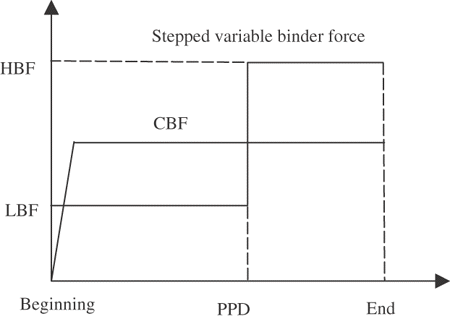
As shown in , the stepped variable binder force curve is different from the CBF as its binder force is not a constant in the forming process. First an LBF is acted on the part, and at one specified percentage of the total punch displacements (PPD), an HBF replaces the LBF. The LBF is intended to facilitate the flow of the material and it should be specified as a small value. The HBF is intended to cause plastic strains in the sidewall and its value should be large. Using this stepped variable binder force, the springback can be reduced Citation1. This curve is determined by three parameters: LBF, HBF and PPD. Liu Citation8 indicated that the LBF should be sufficient to prevent wrinkling. Nevertheless in the U-shaped part forming, there is no wrinkling problem Citation9. Thus the LBF affects the forming quality little and it can be specified as a small and safe constant beforehand. The forming quality of the part mainly lies on the HBF and PPD. As a result, the determination of the variable binder force is actually equivalent to the determination of the HBF and PPD.
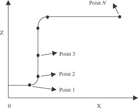
In this paper, an NN model is applied to inversely determine the variable binder force. The outputs of the NN model are the variable binder force parameters (HBF and PPD). The inputs are from the deformation shape of the part. Some key points in the cross section can represent the deformation shape well. As shown in , once the locations of the key points 1 to N are fixed, the deformation shape of the part is determined. The coordinate values of the key points are used as the inputs of the NN model. Combining the HBF and PPD at certain levels and feeding these different combinations into the finite element method (FEM) codes, the corresponding sets of coordinate values of the key points can be obtained. These data will then form the original training samples.
3. The inverse procedure
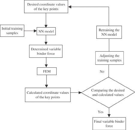
FEM is used as the forward solver to compute the deformation shape of the part and the NN is used as the inverse operator to establish the connections between the deformation shape and the variable binder force. The process is shown in and the detail of each part will be given in the following sections.
3.1. Teacher
The FEM is employed as a teacher for the NN model. Two-dimensional degenerated shell element and elastoplastic material model are used. Hughes and Liu Citation10 gave more details about the description of this shell element and constitutive equations. The part and the tools (punch, die, binder) are specified as slave contact surface and master contact surfaces, respectively. The whole simulation process is divided into two parts: forming and springback. The former uses implicit nonlinear FEM and the latter uses implicit linear FEM. After unloading, displacement and rotation bound conditions are added to restrict the rigid body displacements. The internal forces of the last step in forming process are transformed as the initial point forces of the springback process, and contact forces are calculated by the penalty method Citation11. Feeding a combination of HBF and PPD into the FEM codes, the deformation shape of the part can be calculated.
3.2. Progressive NN
An NN model is referred to as a type of computational model. It is made up of three parts: input layer, output layer and hidden layers. Every layer consists of several neurons. The hidden layers are the bridge between the input layer and output layer. The neurons of neighboring layer are connected by weights that can be specified through training. In this article, the non-linear hyperbolic functions are used as the activation functions to increase the modeling flexibility. A modified back-propagation (BP) learning algorithm with a dynamically adjusted learning rate and an additional jump factor is applied. Using this algorithm, the possible saturation of the sigmoid function can be removed and the training efficiency can be improved. Details can be found in the report by Xu et al. Citation12.
3.2.1. NN model
In the NN model, the number of inputs is constrained by the problem and the number of neurons in the output layer is constrained by the number of outputs required by the problem. An NN model with two hidden layers is used in this article as commended by Masri et al. Citation13 that an NN model with two hidden layers is sufficient in most of the structural problems. The N inputs represent the coordinate values of the key points, while M outputs represent the variable binder force parameters that need to be determined. Mathematically, the NN model represents a non-linear mapping between inputs X = {xi ,i = 1, …, N} and outputs Y = {yi ,i = 1, …, M} via the following equation:
(------148499--1)
where, W =
is a matrix of weights corresponding to the connections between the layers, and Ni and Nj are the numbers of neurons for the ith and jth layers respectively Citation14. The training process is actually to adjust the matrix of W. Once trained, the NN model creates the connections of the involved parameters and can be used to on-line determination. The actual physical model thus can be avoided and the determination efficiency will be very high.
3.2.2. Retraining process
After training, the NN model creates the connections between the deformation shape of the part and the variable binder force parameters. Before on-line determination, a desired deformation shape of the part is needed. Based on this shape, the desired coordinate values of the key points can be obtained and they are used as the inputs to inversely determine the variable binder force. The determined variable binder force is then fed into the FEM codes and one set of calculated coordinate values of the key points can be obtained. Then the calculated coordinate values and the desired ones are compared. If these two sets of data differ much and cannot satisfy the given criterion, the NN model is retrained and the new training samples include the calculated coordinate values and the determined variable binder force. To keep the same number of the training samples, the sample which has the largest distance norm with the desired coordinate values is removed. Once a new sample replaces the remote one, the sample density around the desired coordinate values is increased Citation15. After retraining, the NN model is used to determine the variable binder force again by inputting the desired coordinate values of the key points. The above process will be repeated until the calculated coordinate values are sufficiently close to the desired ones.
4. Application
The U-shaped forming of NUMISHEET’93 as shown in is considered. The geometry and material parameters of the model are listed in . The part is divided into 84 elements. The number of elements contacting the binder is sparse, while one contacting the tools (punch, die) is dense. A half FEM model is built and the computation is accomplished by the FEM codes developed by the laboratory where the authors are working. Tan Citation16 indicated that these FEM codes had very high precision in forming simulation based on the experimental results from NUMISHEET’93.
Figure 4. The U-shaped forming of NUMISHEET’93 (unit: mm) Citation9.
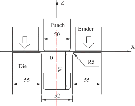
Table 1. The geometry parameters and material parameters of the part
The outputs of the NN model are HBF and PPD. Thus the neuron number of the output layer is 2. To train the NN model 20 samples obtained through the FEM codes are used. The LBF is specified as 2.45 kN. At the CBF of 2.45 kN, the maximum engineering major strain is only 1.93% and it can facilitate the flow of the material. As mentioned in section 2, it is a reasonable value.
4.1. Sensitivity analysis
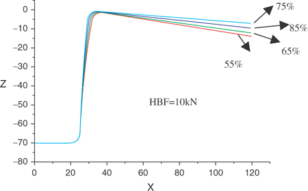
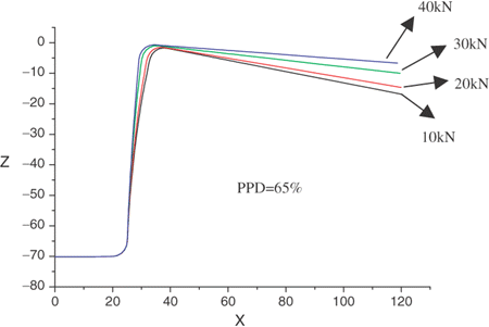
It is a necessary condition for the NN model that the output parameters should be significantly dependent on the input parameters. Thus the sensitivity analysis should be done to investigate whether or not the inputs are sensitive to the outputs. As shown in and , the former specifies the HBF as a constant but changes the PPD while the latter specifies the PPD as a constant but changes the HBF. In both of the figures, it is found that HBF and PPD display an appreciable influence on the upper part of the deformation curve. It means that the key points should be selected in the upper part of the deformation curve.
4.2. Inputs of the NN model
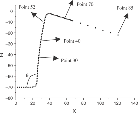
Considering the sensitivity features of and , points 30, 40, 52, 70 and 85 are selected as the key points. Their distribution on the part after springback is shown in . θ is the springback angle. The coordinates of the points 30, 40 and 52 in the X direction vary largely while small in the Z direction under different combinations of HBF and PPD, and the points 70, 85 are on the contrary. So the coordinates of the points 30, 40 and 52 in the X direction denoted by X1, X2, X3 as well as the coordinates of the points 70 and 85 denoted by X4, X5 in the Z direction are used as the inputs of the NN model. Thus the neuron number of the input layer is 5. The neuron numbers of the first hidden layer and the second hidden layer are selected as 16 and 8, respectively.
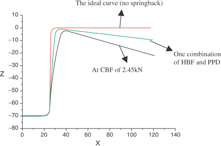
In the NN model, the parameters of inputs and outputs should be given certain variation ranges. The HBF should be larger than LBF, thus 2.45 kN is used as the low bound of the HBF. In order to represent the effectiveness of the present procedure, a relatively large value 40 kN is selected as the high bound of the HBF. At the CBF of 40 kN, the maximum engineering major strain reaches 50% and the material will be cracked. Because the initial LBF is intended to facilitate the flow of the material and this stage should be kept longer, the low bound of the PPD is specified as 55%. HBF is intended to cause plastic strains in the sidewall and make the material of the flange no longer flow into the die cavity. Thus sufficient forming time should be left to the HBF for plastic strains in order to obtain less springback angle. Thus 85% is a proper value as the high bound of the PPD. The springback is largest at the CBF of 2.45 kN, while it is zero just before the springback process. Thus the bounds of the coordinates of the five key points can be confirmed through these two utmost states as shown in .
Before training, the normalization of the inputs and the outputs should be performed. Because the sigmoid transfer function is used in the BP algorithm, the system cannot actually reach the extreme values of 0 and 1 without infinitely large weights. Thus in this application, the inputs and outputs are normalized between 0.1 and 0.9 Citation15.
4.3. The results and discussion
Once the NN model is trained, it can be used to inversely determine the HBF and PPD using a desired deformation shape of the part. Three kinds of methods are used to provide the desired deformation shape in the following sections. The first two methods are based on one assumed combination of the HBF and the PPD, and the third one obtains the desired shape through the CBF simulation.
4.3.1. Noise-free
One assumed combination of HBF = 20 kN and PPD = 75% are fed into the FEM codes to obtain a deformation shape of the part and this shape is regarded as the desired shape. Then the five coordinate values of the key points can be obtained from this shape. These noise-free data are used as the desired coordinate values to determine the HBF and PPD.
The results at stages of progressive training are listed in . It is found that the first determination is not very accurate as the deviation of the PPD reaches 5.6%. With the progressive retraining, the accuracy is improved gradually. After only three progressions, the deviations of the HBF and PPD are decreased to 0.59% and 1.7%, respectively.
Table 2. The results at stages of progressive training (noise free)
4.3.2. Noise added
In the noise free case, the desired deformation of the part is obtained through FEM based on the assumed combination of HBF and PPD, while in practical application the desired shape is given by the engineer. Through some simple graphics knowledge and fundamental springback disciplines of the U-shaped part forming, an engineer can give the reasonable desired deformation shape of the part based on the expected springback angle. Nevertheless, it still depends on the experiences of the engineer more or less and it is nearly impossible to avoid the deviation between the real deformation values and engineer-generated values. Here the same assumed combination of HBF = 20 kN and PPD = 75% is used. A Gauss noise with 1% magnitude Citation14 is directly added to the FEM-generated data to simulate engineer-generated data, and then they are used to inversely determine the variable binder force. The determination results are listed in .
Table 3. The results at stages of progressive training (noise added)
It can be found that the results of the first three progressions are not accurate, as the maximum deviation of the PPD even reaches 15.6%. With more retraining processes, the result becomes more and more accurate. After five progressions, the deviations of the HBF and PPD are 1.5% and 3.6%, respectively. It proves the robustness of the present procedure.
4.3.3. Desired deformation shape
Based on the expected springback angle, the engineer can give one desired deformation shape of the part through the graphics knowledge and the forming disciplines. However, it depends on the rich engineering experiences. If the desired deformation shape deviates the real one much, it will lead to bad results. Here a method, which obtains the desired deformation shape through CBF simulation is recommended for the designers who are short of the engineering experiences.
In the U-shaped part forming, the springback angle will be reduced when the CBF is increased while all other process and material parameters are held constant Citation1. Thus there exists a monotonic relation between the springback angle and the CBF. Through several trials with different CBF using FEM codes, a deformation shape, which has the expected springback angle, can be always obtained. Then this shape can be regarded as the desired deformation shape to inversely determine the stepped variable binder force.
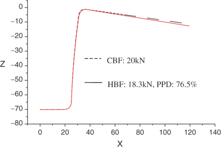
For instance, the springback angle θ = 94°is assumed to be expected. Through several trials, it is found that the deformation shape under the CBF = 20 kN has a springback angle of 94°, thus this deformation shape is used as the desired one to inversely determine the variable binder force. Five progressions of the NN model are performed and the results at every progression are listed in . Feeding the final determined values that HBF = 18.3 kN and PPD = 76.5% into the FEM codes, the deformation shape can be achieved as shown in . It is found that this deformation shape is very close to the desired one.
Table 4. The results at stages of progressive training using CBF simulation method
is the comparison of the mechanical parameters between the CBF and variable binder force. It indicates that through the variable binder force we can obtain the much smaller strain and thickness reduction than the CBF. And it also proves that under the same deformation shape of the part, using variable binder force can prevent the part from being cracked.
Table 5. The comparison of the CBF and the variable binder force
5. Conclusion
In this article, an NN procedure is given to inversely determine the variable binder force based on the desired deformation shape in the U-shaped part forming. A method is suggested to obtain the desired deformation shape based on the CBF simulation for the designers short of the engineering experiences. The computation example indicates that the present procedure can seek the appropriate variable binder force curve according to the designer's expectation.
This article suggests a method for the determination of variable binder force in U-shaped forming. In future study, the experimental work should be considered for the practical application.
Acknowledgment
This work is supported by the national 973 program under the grant number 2004CB719402, the program for New Century Excellent Talents in University, 2004 (NCET-04-0766), and the program under the grant number 51404010205 JB11-04-0766.
References
- Cao, J, Kinsey, B, and Solla, SA, 2000. Consistent and minimal springback using a stepped binder force trajectory and neural network control, Journal of Engineering Materials and Technology 122 (2000), pp. 113–118.
- Ayres, RA, 1984. Shapeset: a process to reduce sidewall curl springback in high-strength steel rails, Journal of Applied Metalworking 3 (1984), pp. 127–134.
- Hishida, Y, and Wagoner, R, 1993. Experimental analysis of blank holding force control in sheet forming, Journal of materials and manufacturing 2 (1993), pp. 409–415.
- Sunseri, M, Cao, J, Karafillis, AP, and Boyee, MC, 1996. Accommodation of springback error in channel forming using active binder force control: numerical simulations and results, Journal of Engineering Materials and Technology 118 (1996), pp. 426–435.
- Schmocket, D, and Beth, M, 1993. Springback reduction in draw bending process of sheet metals, Ann, CIRP 42 (1) (1993), pp. 339–342.
- Cho, S, Cho, Y, and Yoon, S, 1997. Reliable roll force prediction in cold mill using multiple neural networks, IEEE Transactions on Neural Networks 8 (1997), pp. 874–882.
- Di, S, and Thomson, PF, 1997. Neural network approach for prediction of wrinking limit in square metal sheet under diagonal tension, Journal of Testing and Evaluation 25 (1997), pp. 74–81.
- Liu, YC, 1998. The effect of restraining force on shape deviation in flanged channels, Journal of Engineering Materials and Technology 110 (1998), p. 389.
- Liu, G, Lin, ZQ, Xu, WL, and Bao, YX, 2002. Variable blankholder force in U-shaped part forming for eliminating springback error, Journal of Materials Processing Technology 120 (2002), pp. 259–264.
- Hughes Thomas, JR, and Liu, WK, 1981. Nonlinear finite element analysis of shells-part π. two-dimensional shells, Computer Methods in Applied Mechanics and Engineering 27 (1981), pp. 167–181.
- Belytschko, T, Liu, WK, and Moran, B, 2000. Nonlinear Finite Elements for Continua and Structures. London: John Wiley & Sons Ltd; 2000.
- Xu, YG, Liu, GR, Wu, ZP, and Huang, XM, 2001. Adaptive multilayer perceptron networks for detection of cracks in anisotropic laminated plates, International Journal of Solids and Structures 38 (2001), pp. 5625–5645.
- Masri, SF, Chassiako, AG, and Ganghey, TK, 1993. Identification of nonlinear dynamic systems using neural network, Journal of Applied Mechanics 60 (1993), pp. 123–133.
- Liu, GR, Han, X, Xu, YG, and Lam, KY, 2001. Material characterization of functionally graded material by means of elastic waves and a progressive-learning neural network, Composites Science and Technology 61 (2001), pp. 1401–1411.
- Liu, GR, and Han, X, 2003. Computational Inverse Techniques in Nondestructive Evaluation. Florida: CRC Press; 2003.
- Tan, ZP, 2005. "The accurate prediction & optimization technique of the springback based on the genetic algorithm in 2D sheet metal forming". China: Hunan University; 2005, Master thesis.
