Abstract
This article is the second part of a two paper series exploring the application of two advanced computing techniques: artificial neural networks (ANNs) and genetic algorithms (GAs), to the problem of structural parameter identification for an idealised model of an aircraft wing. In this article, GAs are used to determine an idealised finite element model that is representative of the wing of the Pilatus PC-9/A trainer aircraft. This is achieved through an optimisation process that attempts to match the static and dynamic response of the model to measured aircraft structural responses. A number of approaches were trialed with improvements made to each successive approach in an attempt to find a suitable unique parameter set. Structural parameters were found for a three-element model which has characteristics very similar to those of the PC-9/A wing. A comparison is also provided between the performance of the neural network and GA approaches.
1. Introduction
Engineering is preoccupied with representing real world structures in an idealised mathematical environment. In order to have a finite element model (FEM) of an aircraft structure that is tractable for static and dynamic analyses, it is beneficial to represent the aircraft structure using a simple model Citation1. Over the past three decades, there has been a growing body of research dedicated to finding the best means of creating such simplified models that adequately describe the true behaviour of the structure.
Parameter identification is the task of finding values for quantities which are required to create a mathematical model which adequately represents a structure or object. This article presents a parameter identification procedure for determining the structural (i.e., stiffness and mass) properties of a simple model such that it is representative of an actual aircraft. The model was constructed from relatively simple beam or frame elements, making the process of idealising such a complex aircraft structure a challenging one.
The problem was complicated by the limited data available for the aircraft being analysed. For the PC-9/A trainer aircraft flown by the Royal Australia Air Force (RAAF), data was available in the form of natural frequencies and mode shapes of the main wing, a mass distribution and static deflection data. Given this unique combination of available data, it was necessary to find a parameter identification procedure that was adaptable enough to cope with this particular situation.
2. Background
Since their development, genetic algorithms (GAs) Citation1 have been used to solve a wide variety of problems ranging from the design of an optimal jet engine Citation2, control in a gas pipeline Citation3,Citation4, modelling of natural evolutionary systems Citation4 and more recently in the arena of aircraft parameter identification.
Perhaps the most relevant and applicable work performed in this area has been by Dunn Citation1,Citation5–8, who has successfully utilised GAs to solve an optimisation problem, which attempts to match the frequency response of an idealised aircraft model to frequency response data obtained through model testing or from a more complex FEM. Whilst this approach and the data utilised are slightly different from the problem here, the versatility of the method presented by Dunn, and the adaptable nature of GAs, suggested that they were suitable for the application to the parameter identification of the PC-9/A.
3. Genetic algorithms
The GAs are a form of stochastic function optimisation recognised for their ability to solve optimisation problems having an irregular state space. They utilise a family of individual members representing solutions to the optimisation problem, which can be manipulated over successive generations, until an optimum solution is discovered. At each generation, members with admirable traits, or those that are deemed as having a high level of fitness (as determined by a specified fitness or evaluation function) are retained and bred with other individuals of high fitness. The result is such that admirable traits are ‘passed down’ through generations, with the less fit members generally being eliminated. The procedure used to select the individuals who will become the parents of the next generation is governed by a selection function and weighted chance. The selection procedure has a significant impact on the outcome of the GA. Once selection has taken place, the new generation is produced through the use of genetic operators, the most common of which are crossover and mutation. The use of both operators is beneficial and generally results in reduced likelihood of solutions remaining stuck in local minima or maxima. The GA progresses through generations, returning the fitness of the best member of the population, until particular termination criteria are met.
A Genetic Algorithm Optimisation Toolbox (GAOT) Citation9 developed in MATLAB® was used to provide the required GA functionality. Parameters defining the type and extent of crossover and mutation, and type of selection function were chosen to be the defaults associated with the GAOT. The GA was initialised with a randomly generated population of members comprised of values for design variables, which fall within a range specified for each variable. For optimisations presented here, populations consisting of 100 randomly generated members were used. Larger populations were tested with no significant improvement in the performance of the optimisation process.
4. Model development
4.1. The aircraft
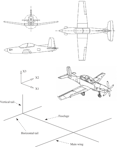
The Pilatus PC-9/A is a two seat trainer aircraft of conventional configuration. It has a wingspan of 10.12 m, a length of 10.17 m and an empty weight of approximately 1700 kg. It is powered by a Pratt & Whitney PT6A-62 turboprop engine of 950 shp and is capable of a maximum speed of 300 kts. A diagram of the PC-9/A can be seen in .
4.2. Available data
The methods which could be utilised to determine the structural parameters for an idealised model of the PC-9/A were limited by available aircraft data. Two important data sets were available, which were derived from actual experimental work carried out on a PC-9/A aircraft (see the following).
4.2.1. Ground vibration test (GVT) data
The GVT data was measured using an RAAF PC-9/A. Testing was only completed on the wing of the aircraft, yielding natural frequencies and mode shapes for three bending modes (1st symmetric, 1st antisymmetric and 2nd symmetric).
4.2.2. Static deflection data
Static deflection testing was carried out by DSTO on a PC-9/A airframe in a fatigue test rig. Digital photogrammetry was used to measure the deflections of over 200 points on the aircraft in response to eight load cases. Applied force and resulting deflection data was available.
4.3. The model
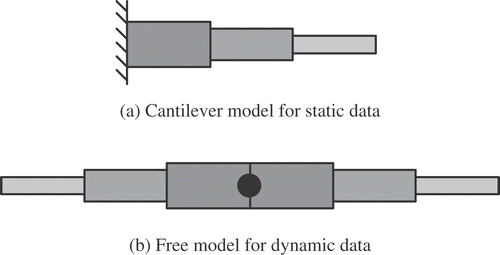
An idealised model used to represent the wing of the PC-9/A was constructed from planar beam elements. This model varied in configuration depending on the method utilised to determine the properties associated with the PC-9/A wing. In cases where static deflection data was used, a cantilever model of a wing semi-span, as shown in , was chosen to represent the wing. The model shown here has three elements, each with different properties and constant length. The number of elements can vary in order to obtain the optimum model. When mode shape or natural frequency data was used, a symmetric full span model subject to no boundary conditions, as shown in , was chosen.
5. Parameter estimation using GAs
The goal of the task here was to find stiffness and mass properties for a model comprised of planar beam elements, which are used to represent the wing of the PC-9/A aircraft. The stiffness and mass properties required include:
| a. | bending stiffness, EI | ||||
| b. | mass per unit length, ρA | ||||
| c. | rotational inertial per unit length, ρI | ||||
The problem was formulated as an optimisation task, which traditionally involves establishing design variables or parameters which can be modified in order to change the model, state variables which provide an indication of the current state of the model, and a fitness or evaluation function, which is usually a function of the state variables and provides a measure of how good or fit a particular solution is.
In this case, the design variables are the stiffness and mass properties mentioned previously, whilst the state variables are quantities which are part of or can be determined from available experimental data pertaining to the PC-9/A. It is also necessary that these quantities can be calculated using the FEM.
The evaluation function compares state variables calculated using the FEM to those determined from the available experimental data. The evaluation function was therefore of the form:
(1)
where J is the value of the evaluation function, A is a parameter or state variable available for comparison, n is the number of parameters and the subscripts m and d refer to parameters determined from the FEM or the available experimental data respectively. The evaluation function is negative as the GA toolbox utilised is designed to maximise the value of the evaluation function. The evaluation function specified above will therefore minimise the difference between the model and data values of the state variables when its value is a maximum.
5.1. Optimisation procedure
The choice of evaluation function can have a significant impact on the results of the optimisation process. Therefore, a number of approaches were trailed which used evaluation functions comprised of various combinations of the state variables in order to determine the required structural parameters.
For each approach, four models possessing from N = 1 to 4 elements per semi-span were used. For each of these cases, 20 runs of the GA were carried out resulting in 20 possible solutions. Of these 20, the solution with the lowest evaluation function value was deemed to be the best solution.
5.1.1. Approach 1
The first approach utilised an evaluation function which compared the numerical FEM results with experimental natural frequencies, ω, mode shapes, U, and total mass of the PC-9/A wing, mw, in order to estimate both the mass and stiffness properties of the idealised model. Thus, the design variables were the mass and stiffness properties of each element, and the state variables were the first three natural frequencies, mode shapes and wing mass. These variables, therefore, comprised the components of the evaluation function.
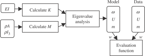
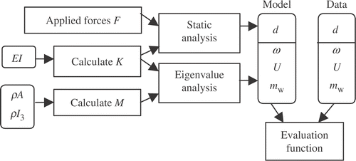
A depiction of the operations required in order to determine the state variables which make up the evaluation function can be seen in . In this figure, K and M represents the system stiffness and mass matrices respectively.
The natural frequencies of the models representing the best solution for each case can be seen in . The results are presented in the form of normalised frequencies which are natural frequencies of the model divided by the fundamental frequency of the PC-9/A aircraft.
Table 1. Approach 1 – normalised frequencies
It can be noted from that the quality of the solutions in terms of their ability to match the natural frequencies of the PC-9/A improved significantly as the number of elements increased. Both the N = 3 and N = 4 cases could be deemed satisfactory. It should also be noted that in all cases, the GA was able to match the wing mass to within less than 1%.
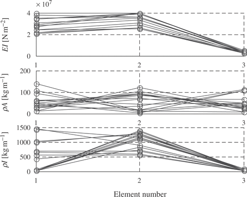
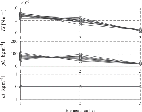
Upon viewing results for each of the 20 solutions, however, it was evident that significant uncertainty existed. A depiction of each of the solutions, showing the results for EI, ρA and ρI for each element in the three element or N = 3 case can be seen in .
It can be noted from that the solutions vary over a significant range, indicating that the GA is struggling to find a unique solution. This trait was evident regardless of the number of elements used for the model, and is generally associated with an attempt to glean more information from the available data and then it is possible to extract.
Thus, as only a small degree of confidence could be placed in the GA's ability to determine a unique solution given the conditions used in this approach, it was necessary to modify the approach in an attempt to improve this result.
5.1.2. Approach 2
The second approach was similar to the first, but involved modification of the model to include a lumped mass at its centreline to represent the inertial characteristics of the fuselage, engine and empennage of the aircraft. This lumped mass was comprised of only a translational inertia, and excluded a rotational inertial component for the reasons outlined next.
shows a comparison between the normalised natural frequencies of the PC-9/A wing and those of a continuous beam having constant properties along its length. Whilst the first two natural frequencies are similar, the third is significantly different, meaning that to produce a model constructed from continuous beam elements that is representative of the PC-9/A, significant changes must be brought about in the distribution of the natural frequencies through changes in the design variables.
Table 2. Natural frequencies of PC-9/A wing vs. continuous beam
Although a simple solution to this problem would be an alteration of just the third natural frequency, no mechanism exists to change only this frequency without influencing the others. Thus, the frequency distribution must be altered.
This can be achieved by either increasing the second natural frequency relative to the first and third, and then reducing all the natural frequencies, or by increasing the first and third and then increasing all the natural frequencies.
Inclusion of a lumped mass assists this process because the translational inertial will only influence the first and third (or symmetric) frequencies, whilst the rotational inertial will only influence the second (or anti-symmetric) frequency. So, when a lumped mass is included, the GA attempts to resolve the frequency spacing issue by increasing the value of the translational inertia indefinitely and reducing the value of the rotational inertia to zero.
This is obviously not desired, and as a result the translational inertial was set at a fixed value equal to the empty weight of the aircraft minus the mass of the wing, while the value of the rotational inertia was set to zero, effectively excluding it. The translational inertial was retained, as it was noted that its inclusion did improve the GA's ability to find a satisfactory solution.
5.1.3. Approach 3
This approach utilised an evaluation function based only on static deflection data. As this data was not influenced by the inertial properties of the aircraft, it could only be used to determine the stiffness properties for the model. To calculate the state variables required for comparison in the evaluation function, force and moment data, F, for each of the load cases was converted to nodal loads and applied to the FEM. The resulting deflections and slopes, d, were compared with the measured deflection data. A flow chart of the process involved can be seen in .
In general, agreement between the values of the state variables calculated using the model, and those associated with the static deflection data, was quite good.
There was also very little uncertainty in the solutions obtained, with stiffness values covering only a small range. This is quite possibly a result of the significant amount of data used in the evaluation function (i.e., deflection and slope data at each node for each load case), and the reduction in the number of parameters to be obtained.
The stiffness values in this case were, however, significantly lower than those found using the previous approaches, the cause of which was discovered during the development of Approach 4.
5.1.4. Approach 4
It was realised that the values obtained for ρI in Approaches 1 and 2, were quite large. As this parameter represents the rotational inertia associated with mass offset from the longitudinal axis of a beam element, it was decided that these values were significantly higher than that is reasonable.
In general, ρI only has an impact on the higher natural frequencies of a structure, which explains why large values were required in order to influence the first three natural frequencies of the model.
Consequently, an approach was trialed which utilised the same evaluation function and procedure as Approach 2, but fixed the value of ρI for each element to zero, eliminating its influence. It was realised that this significantly reduced the values of EI obtained, making them comparable with those obtained using Approach 3. This also had the benefit of reducing the number of parameters the GA had to determine, and increasing the chance of a unique solution being found.
5.1.5. Approach 5
The final approach involved the combination of Approaches 3 and 4, such that as much data as possible could be used in the evaluation function in the hope of reducing the uncertainty associated with solutions in the previous approaches. This meant that the static and dynamic data were included, and that both the static problem and eigenvalue problem are needed to be solved in order to determine the state variables required by the evaluation function. A flow chart of the process can be seen in .
shows a plot of the design variables versus element number for the three element case. It can be seen that the solutions are relatively well-defined with significantly less uncertainty than that which is evident in the results from the first approach as shown in . It is also evident that the value of EI has reduced significantly, due to the exclusion of ρI.
The best member from the three-element case was chosen as the final solution, for a number of reasons. shows the normalised frequencies of the best solutions from each case (i.e., N = 1–4). The N = 3 case possesses the smallest errors for each of the solutions.
Table 3. Approach 5 – normalised frequencies
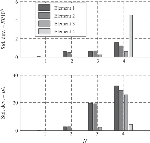
In addition, shows a comparison of the standard deviation of the values of EI and ρI obtained from the 20 solutions for each case. The standard deviation provides a measure of the spread of the results obtained and therefore gives some indication of the degree of uncertainty in the solutions. A lower standard deviation should, therefore, provide a greater confidence that a unique solution has been obtained.
It can be noted that the standard deviation increases as the number of elements increases, indicating greater solution uncertainty: however as and show, as the number of elements increases so does the solution accuracy. The N = 3 case, therefore, represents a compromise between solution accuracy and solution uncertainty.
5.2. Performance of approaches
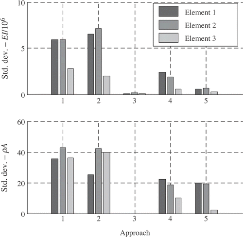
Another interesting comparison can be made by viewing the standard deviation of the values of EI and ρI obtained in the N = 3 case for each of the approaches, as shown in . It can be seen that the successive improvements made to the approaches significantly reduced the standard deviation and therefore the solution uncertainty. Approach 3 possessed the least uncertainty; however, it was incapable of determining the inertial properties.
5.3. Solution
shows the values for the stiffness and mass properties of the chosen solution. It can be noted that the values for bending stiffness and mass per unit length decrease as they shift outboard, as would be expected in an aircraft with a tapering wing.
Table 4. Material and section properties for experimental model
6. Comparison with ANNs
This section deals with the comparison between the application of ANNs and GAs to the aircraft structural parameter identification problem, in particular to the case of determining an idealised model for the PC-9/A. In order to facilitate such a comparison, the reader is referred to the first part of the two-paper series undertaken by Trivailo et al. Citation10, which highlights the application of neural networks to the aircraft structural parameter identification problem. The nature of the data available for the PC-9/A is unsuitable for use in the neural network-based method (see Citation10); hence a direct quantitative comparison between the two methods cannot be made. Instead, the comparison is limited to being qualitative only.
The main advantages of ANNs are their massively parallel architecture and ability to learn and generalise Citation11. Their input/output mapping capability, robustness and ease at accommodating non-linearity also render them attractive for parameter identification problems Citation10. Alternatively, the global search capabilities, inherent non-linearity, robustness and familiar optimisation implementation of GAs are valuable attributes for their application to the parameter identification problem. Common to both methods is the disadvantage associated with being unable to guarantee that the parameters identified will yield a structure that is physically representative. The need for an accurate and highly representative data set for ANN training is the main disadvantage associated with ANNs for parameter identification Citation10, whilst the need to recast the optimisation process every time when the parameter identification process needs to be undertaken is an inherent shortfall associated with GAs.
Application of GAs to the structural parameter identification of the PC-9/A demonstrates that the GAs are better suited to problems when available data relevant to the problem under consideration is limited. It is here that one can take advantage of the adept global search capabilities of GAs to elucidate a unique solution that for most practical problems is difficult to achieve. While the training of an ANN requires a relatively large, yet highly accurate and representative set of data, which was not available in the case of the PC-9/A, it is evident that the GA was still successful in determining a unique parameter set for the structure.
Developmental and set-up times are generally lower for the case of GAs as compared to ANNs, due to the nature of the application of the two techniques. The implementation of GAs for parameter identification is essentially large-scale multi-objective optimisation, which has been extensively developed and is generally well known to engineers and scientists. On the other hand, the rather unorthodox and less familiar implementation of ANNs demands more time from the user to both learn and execute. Similarly, no training process is required when using GAs, simply execution, which also helps to reduce set-up times.
However, this may not always be the case and if certain circumstances change, it is possible for set-up and developmental times to be kept modest if one cleverly exploits the capabilities of ANNs. The learning and generalisation capabilities of ANNs are useful if and when the mechanical behaviour of the structure is to change for some reason. The effects of fatigue on an aircraft structure or a slight design or configurational modification may have a noticeable effect on its observed mechanical and modal response. Armed with a new set of data concerning the mechanical modal response of the structure, one may wish to identify a new parameter set for the structure. In the case of GAs, the entire optimisation process needs to be repeated, but for a correctly trained ANN, this new data set simply needs to be shown to the ANN, and a new parameter set for the structure will be returned almost instantaneously. Here lies the power of the input/output mapping capability and robustness of ANNs.
In light of the advantages and disadvantages associated with the application of the two procedures discussed previously, it follows that a hybrid procedure encompassing both GAs and ANNs should be explored. Here the global search capabilities of GAs could be used to determine unique parameter sets for aircraft structures similar to that under consideration. Then the input/output mapping capability and robustness of ANNs could be utilised by using the aforementioned parameter sets found using GAs to train an ANN. This successfully trained ANN could then be used to recover the parameters of a structure as its observed mechanical and modal behaviour varies. This hybridisation eliminates the disadvantages of each individual procedure, whilst consolidating their strengths. The development of this hybrid artificial intelligence optimisation procedure to be applied to the aircraft structural parameter identification problem will be the subject of future research activities.
7. Conclusions
The second part of this two paper series presents a procedure that utilises genetic algorithms (GAs) for determining parameters of an idealised aircraft model. The procedure is capable of determining structural parameters for a model constructed from planar beam elements such that calculated static response and dynamic characteristics match static deflection and ground vibration test data. A number of approaches were trialed before finding a suitable approach which provided a solution offering a reasonable compromise between solution accuracy and uncertainty.
The first part of this series described an attempt to use artificial neural networks (ANNs) to perform a similar task, and as such a comparison is provided between the advantages and disadvantages of each. A procedure which exploits the advantages of both procedures is proposed to further improve the performance of the parameter identification task.
Acknowledgements
The authors would like to acknowledge the support of the Defence Science Technology Organisation (DSTO), Australia, and in particular Dr. Douglas Sherman from the Platform Sciences Laboratory of DSTO.
References
- Dunn, SA, The use of genetic algorithms in dynamic finite element model identification for aerospace structures. Presented at presented at the 20th Congress of the International Council of the Aeronautical Sciences. Goldberg, Virginia, USA, 1996.
- Baker, D, 1989. Genetic Algorithms in Search, Optimization and Machine Learning. Reading, MA: Addison-Wesley; 1989, Reading.
- Holland, JH, 1992. Genetic algorithms, Scientific America 267 (1992), pp. 44–50.
- Forrest, S, 1993. Genetic algorithms: principles of natural selection applied to computation, Science 261 (1993), pp. 872–878.
- Dunn, SA, 1997. Modified genetic algorithm for the identification of aircraft structures, Journal of Aircraft 34 (2) (1997), pp. 251–253.
- Dunn, SA, Optimisation of the structural dynamic finite element model for a complete aircraft. Presented at presented at the 21st Congress of the International Council of the Aeronautical Sciences. Melbourne, Victoria, Australia, 13–18, September, 1998.
- Dunn, SA, 1998. The use of genetic algorithms and stochastic hill-climbing in dynamic finite element model identification, Computers & Structures 66 (4) (1998), pp. 489–497.
- Dunn, SA, 1999. Technique for unique optimisation of dynamic finite element models, Journal of Aircraft 36 (6) (1999), pp. 919–925.
- Houck, C, Joines, J, and Kay, M, 1995. A Genetic Algorithm for Function Optimization: A MATLAB Implementation. North Carolina State University: North Carolina; 1995.
- Trivailo, PM, Dulikravich, GS, Sgarioto, D, and Gilbert, T, 2004. Inverse problem of aircraft structural estimation: application of neural networks. Presented at Presented at the Inverse Problems, Design and Optimization Symposium. Rio de Janeiro, Brazil, 17–19, March, 2004.
- Haykin, SS, 1999. Neural Networks: A Comprehensive Foundation. Prentice Hall: New Jersey; 1999.
